


5.8GHz RF Output can drop more easily than 900MHz because high-frequency bands are less forgiving when RF Power Amplifier efficiency, matching networks, PCB paths, connectors, feeder loss, antenna VSWR, heat, and measurement boundaries are all included. A 100W result at 900MHz does not prove that the same usable output will remain at 5.8GHz after the cabinet, feeder path, connector transitions, antenna installation, and duty-cycle conditions are added.
The central conflict is simple: 900MHz often tolerates RF path imperfections better, but 5.8GHz exposes small losses and mismatch faster. For system integrators, RF engineers, and procurement reviewers, the practical question is not only whether a module covers 5.8GHz. The harder question is whether 5.8GHz can still deliver usable antenna-port power under the real cabinet, feeder, connector, antenna, thermal, supply, and protection conditions of a C-UAS deployment.
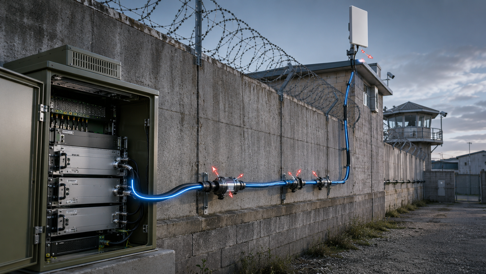
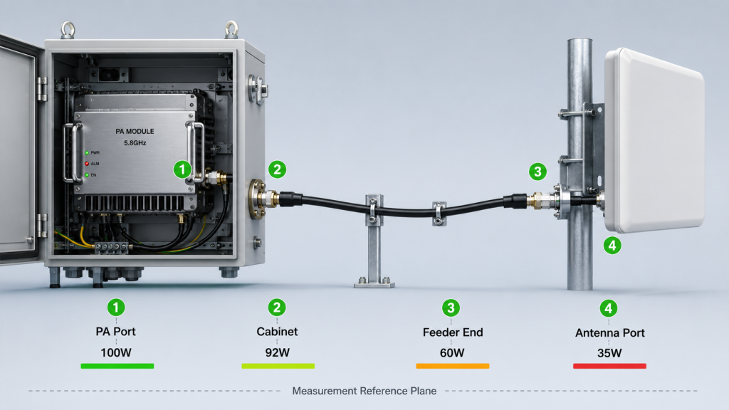
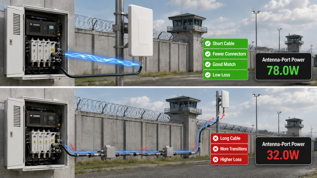
This matters in prison and high-security facilities because rooftop antennas, guard towers, high walls, metal structures, remote feeder paths, and limited maintenance windows can make high-frequency output problems harder to isolate after installation. The better approach is to define the measurement point first, then compare PA-port output, cabinet output, feeder-end power, antenna-port power, VSWR status, thermal margin, supply behavior, and repeatable test evidence.
1. What Makes RF Power Amplifier Output Drop at 5.8GHz
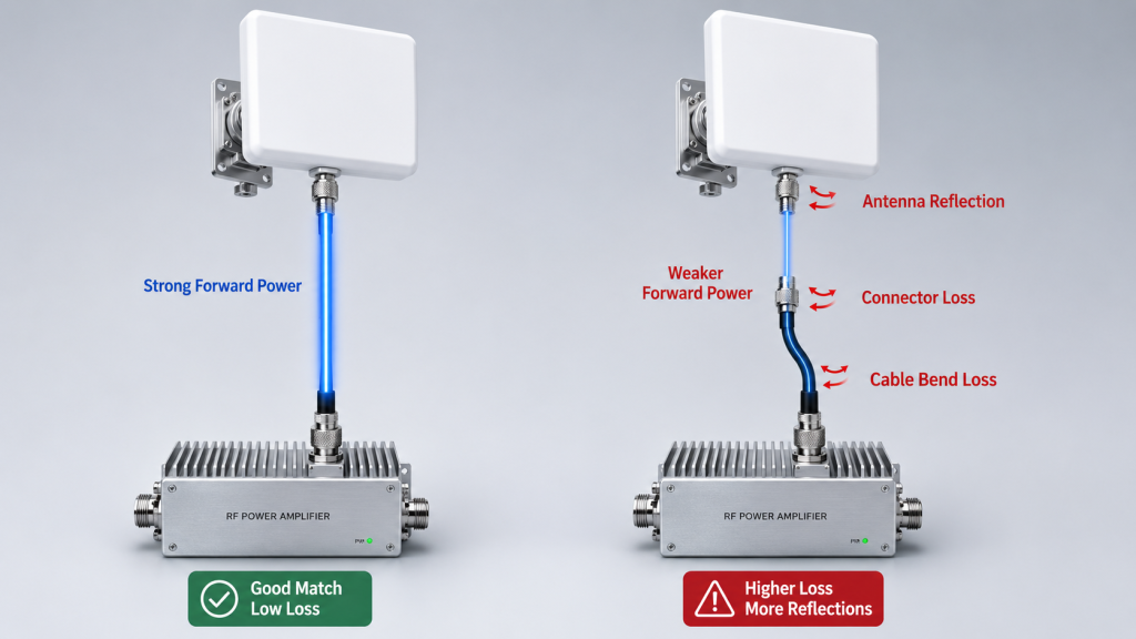
5.8GHz is more sensitive than 900MHz because RF Power Amplifier Output Power at higher frequency is affected more quickly by small impedance changes, connector transitions, PCB parasitics, feeder loss, antenna VSWR, and measurement-boundary differences. At 900MHz, the same physical connector, cable bend, adapter stack, or antenna mounting condition may still look acceptable. At 5.8GHz, that same detail can become visible as insertion loss, reflected power, unstable output, or a lower antenna-port reading.
Here’s the engineering point: the frequency is not just a number on the module label. It changes how strongly the system reacts to small RF path errors. When evaluating RF Power Amplifier modules for C-UAS integration, you should not use a stable 900MHz reading as proof that 5.8GHz will behave the same way after installation.
What Changes When the Frequency Moves Higher?
At 5.8GHz, the RF path has less tolerance for physical and electrical imperfections. A connector that looks clean, a short adapter that feels harmless, or a feeder route that seems acceptable at 900MHz may create more measurable loss at the higher band.
Check these before comparing 5.8GHz with 900MHz:
- Was power measured at the PA port, cabinet output, feeder end, or antenna input?
- Was the same cable path used for both frequency bands?
- Were connector and adapter transitions counted?
- Was the 5.8GHz antenna matched after installation?
- Was output measured after heat stabilized?
- Was 5.8GHz near the edge of a wideband module range?
- Was VSWR or reflected power recorded during the test?
Why Does This Matter for Real Selection?
The risk is not that 5.8GHz is “bad.” The risk is that teams may approve a PA based on lower-frequency confidence, then discover that the high-frequency band has less usable margin after real installation. That can lead to late cable changes, antenna retesting, extra cooling review, or disputes over whether the module or the installed RF chain caused the drop.
Key Takeaway: 5.8GHz output should be judged as a high-frequency system result, not as a simple extension of 900MHz module behavior.
| Wrong Assumption | Better Check |
|---|---|
| “900MHz passed, so 5.8GHz should pass.” | Verify 5.8GHz output separately. |
| “100W means the same thing at every band.” | Define frequency, port, load, and path. |
| “The PA module is the only cause of output drop.” | Check PA, PCB, connector, feeder, antenna, and heat. |
| “A short bench test proves field output.” | Compare installed antenna-port evidence. |
This table helps engineers prevent a lower-frequency pass result from becoming false confidence at 5.8GHz.
2. How to Trace RF Power Amplifier Output Drop
A 5.8GHz output drop is not always a module failure because RF Power Amplifier Output Power can fall after the PA port due to measurement boundary changes, feeder loss, connector loss, antenna mismatch, temperature rise, supply behavior, or field installation conditions. If the module passes on a short factory path but drops at the antenna end, the first step is to locate where the drop occurs.
The practical risk is clear: if you blame the module too early, you may replace a working PA while leaving the real RF path problem unchanged. A fair diagnosis compares PA-port data, cabinet output, feeder-end reading, and antenna-port output before assigning the cause.
Where Should Engineers Look First?
Start by separating module behavior from installed RF chain behavior. A 5.8GHz drop may be real, but it may not be caused by the amplifier itself.
Common non-module causes include:
- Factory short-cable test vs field long-feeder test
- Dummy load test vs real antenna test
- PA-port reading vs antenna-port reading
- Unrecorded adapter or lightning protector
- Poor connector contact at high frequency
- Antenna VSWR change after mounting
- Heat-related output reduction after long duty
- Instrument or coupler frequency limitation
How Should the Drop Be Located?
The drop should be located by testing the same frequency across several boundaries. If 5.8GHz is normal at the PA port but lower after the feeder, the installed RF path deserves review. If it is already low at the PA port under controlled load, the module, drive condition, supply, thermal state, or high-frequency design margin deserves closer review.
Key Takeaway: A 5.8GHz drop becomes meaningful only after you know whether it happened inside the PA, after the cabinet output, along the feeder, or at the antenna input.
| Symptom | Possible Cause |
|---|---|
| PA-port output is normal, antenna output is low | Feeder or connector loss |
| Dummy load is normal, antenna test drops | Antenna mismatch or VSWR |
| Short test passes, long test drops | Thermal or duty-cycle effect |
| One setup passes, another fails | Measurement boundary mismatch |
| Drop appears only after cabinet integration | Cabinet feedthrough or interface issue |
This table helps you diagnose the output drop before turning it into a supplier dispute.
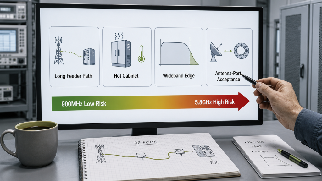
3. When Does 5.8GHz Output Drop Become a Selection Risk?
A 5.8GHz output drop becomes a selection risk when RF Power Amplifier Output Power at that band is mission-critical and the installed RF path must still deliver enough antenna-port power under real C-UAS conditions. If 5.8GHz is only a secondary band, a small reduction may be manageable. If it is a required channel, the same reduction can change the whole selection decision.
This is where system integrators should pay attention: high-frequency output risk is not only a lab result. It affects PA rating, cable grade, antenna placement, cooling reserve, supply margin, protection feedback, and acceptance evidence.
Which Conditions Raise the Risk?
You should treat 5.8GHz output drop as a selection risk when the field system depends on that band and the installation path is complex. The more the field path differs from the factory path, the more careful the high-frequency review should be.
High-risk conditions include:
- 5.8GHz is a required operating band
- The antenna is far from the PA cabinet
- Feeder length is longer than the test setup
- Connector and adapter count is high
- Rooftop or guard tower antenna paths are used
- The module runs long-duty or high-duty operation
- Cabinet temperature can rise during service
- 5.8GHz sits near a wideband edge
- Acceptance requires antenna-port verification
What Makes It a Procurement Issue?
The procurement risk appears when the RFQ only says “5.8GHz 100W” without defining where that power is required. A supplier may quote based on PA-port output, while the system integrator expects antenna-port power after feeder, connector, and antenna conditions are included.
Key Takeaway: 5.8GHz output drop becomes a selection issue when that band must survive the installed feeder path, antenna condition, heat, duty cycle, and acceptance boundary.
| Field Condition | Selection Risk |
|---|---|
| 5.8GHz is mission-critical | Output drop directly affects approval |
| Long feeder path | Antenna-port power may fall faster |
| Hot cabinet | Thermal margin becomes tighter |
| Wideband edge | Output flatness may be weaker |
| Real antenna test required | VSWR and installation quality matter |
| Undefined output point | PA-port and antenna-port expectations conflict |
This table helps procurement teams decide when a high-frequency result needs deeper review before module approval.
4. How Does 5.8GHz Drop Affect Real C-UAS Performance?
A 5.8GHz drop affects real C-UAS performance when RF Power Amplifier Output Power falls at the installed antenna port, not only when a PA-port reading changes. The system does not use catalog wattage directly; it uses whatever power remains after the module, cabinet, feeder, connector path, antenna match, and protection behavior are included.
Here’s the field reality: two systems can use the same PA rating but produce different high-frequency results after installation. In Low-Altitude Security & C-UAS EW Solutions, high-frequency output should be judged by system-side usable power, not only by clean bench data.
What System Questions Should Be Asked?
The right question is not “Does the PA have 5.8GHz?” The better question is “Where does 5.8GHz still have enough usable output?” That question keeps the review tied to real integration instead of catalog comparison.
Ask these questions during review:
- Is 5.8GHz power required at the PA port or antenna input?
- Does the high-frequency path include extra connectors?
- Are antenna positions different across coverage directions?
- Does VSWR change after installation?
- Does output remain stable after heat builds?
- Does the test report separate PA data from system data?
Why Can Measurement Points Create Disputes?
Measurement points create disputes because PA-port power, cabinet output, feeder-end power, and antenna-port power are not the same result. A supplier may show normal PA-port data, while a field team measures lower antenna-port data after the installed RF path. Both readings can be technically correct but not directly comparable.
Key Takeaway: A 5.8GHz drop matters most when it reduces the antenna-port power that the installed C-UAS system depends on for stable high-frequency operation.
| Measurement Result | What It Mainly Shows |
|---|---|
| PA-port 5.8GHz output | Module-side capability |
| Cabinet output | Cabinet and interface loss |
| Feeder-end output | Cable delivery result |
| Antenna-port output | Installed system input condition |
| Field performance concern | Whole system behavior |
This table helps teams avoid comparing unlike measurement points when judging high-frequency system performance.
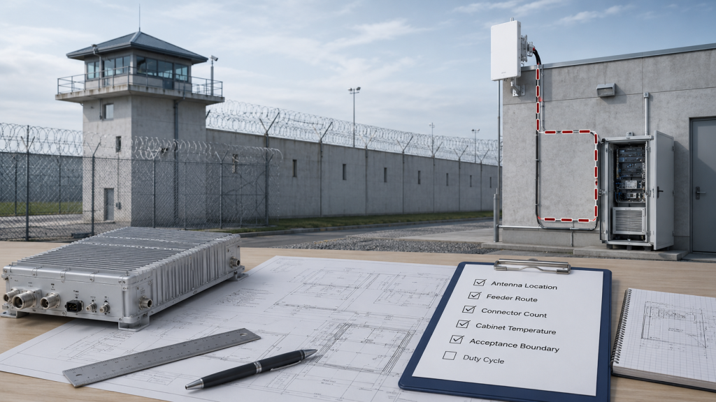
5. What Do Prison Sites Reveal About 5.8GHz Loss?
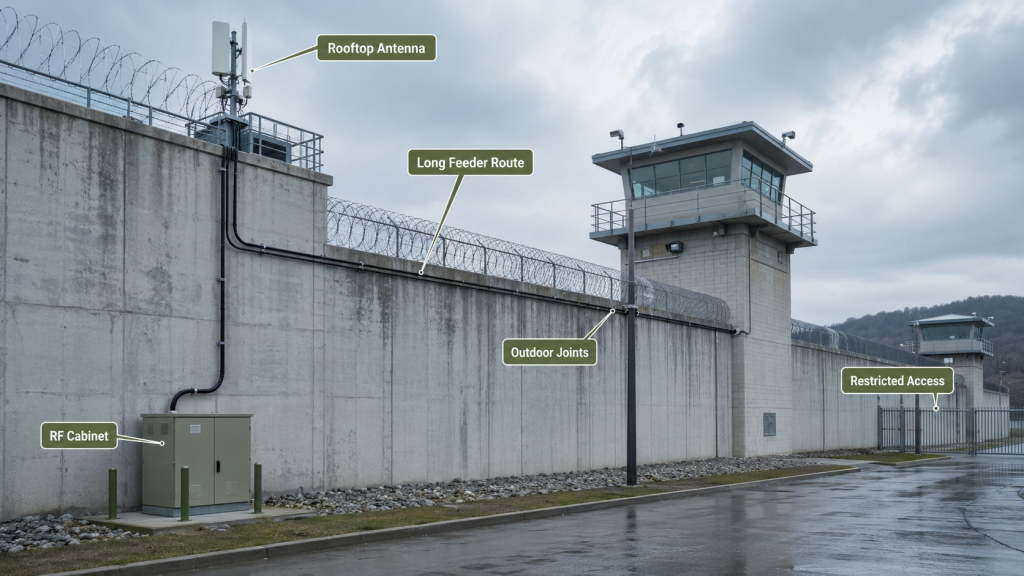
Prison sites reveal 5.8GHz loss because RF Power Amplifier Output Power at high frequency can be reduced by rooftop antenna paths, guard tower routing, high-wall cable runs, metal structures, multiple connectors, and limited maintenance access. These conditions do not make 5.8GHz unsuitable, but they make careless high-frequency assumptions more expensive.
In a prison and high-security C-UAS deployment, the RF path is often shaped by security layout, mounting restrictions, access control, and maintenance windows. That means high-frequency verification should be planned before the final cabinet and antenna route are locked.
Which Prison Conditions Make 5.8GHz Harder?
The challenge is usually not one dramatic failure. It is the stacking of small high-frequency sensitivities across the installed RF chain.
Common site factors include:
- Antennas on guard towers or rooftops
- Cable routes through walls or service shafts
- Waterproof outdoor joints
- Lightning protection near exposed points
- Metal fences, brackets, and mounting structures
- Different feeder lengths for different directions
- Restricted access after installation
- Limited time for repeated field retesting
Why Does Limited Maintenance Change the Decision?
Limited maintenance changes the decision because a high-frequency problem found after installation can be harder to correct than a low-frequency bench deviation. Retightening connectors, changing feeder routes, moving antennas, or retesting rooftop paths may require access approval, security coordination, and system downtime.
Key Takeaway: Prison and high-security sites make 5.8GHz verification more important because access, routing, structures, and maintenance limits can turn high-frequency loss into a field acceptance problem.
| Site Condition | 5.8GHz Risk |
|---|---|
| Rooftop antenna | Longer feeder path |
| Guard tower route | More connector transitions |
| Metal structure nearby | Antenna match sensitivity |
| Restricted maintenance | Harder post-install correction |
| Multiple antenna directions | Uneven high-frequency output |
| Wall or shaft routing | Hidden cable and connector stress |
This table helps engineers connect facility layout decisions with high-frequency RF output risk.
6. How to Diagnose RF Power Amplifier Output Drops
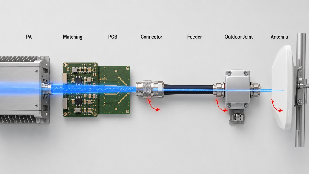
RF chain losses add up at 5.8GHz because RF Power Amplifier Output Power can be reduced by amplifier efficiency, PCB path loss, matching-network sensitivity, connector transitions, feeder cable loss, antenna VSWR, heat buildup, and protection behavior at the same time. A high-frequency output drop is often not one isolated failure. It is the visible result of several small losses stacking across the RF chain.
The selection risk appears here: if you only inspect the feeder cable, you may miss high-frequency output flatness or PA thermal behavior. If you only inspect the module, you may miss connector loss, adapter transitions, lightning protection, antenna mismatch, or installation-related VSWR. Both mistakes can lead to the wrong corrective action.
What Parts of the Chain Should Be Reviewed?
At 5.8GHz, every part of the output path should be assigned a role in the review. The point is not to make the project more complicated. The point is to avoid blaming the wrong subsystem.
Review these areas together:
- PA device efficiency and gain reserve at 5.8GHz
- Matching-network behavior near the high-frequency band
- PCB path, shielding cavity, and package transition sensitivity
- Connector, adapter, and cabinet feedthrough quality
- Feeder length and cable loss at 5.8GHz
- Antenna VSWR after real mounting
- Thermal rise during sustained output
- Module-end voltage under full load
- VSWR, temperature, voltage, and current feedback
Where Can a Small Loss Become a Large Problem?
A single connector or short adapter may not look serious in isolation. The problem appears when several high-frequency-sensitive points are added together: PA output tolerance, cabinet interface, feeder cable, waterproof connector, antenna match, and heat. At 5.8GHz, that stack can reduce antenna-port power even when the PA-port result still looks acceptable.
For wideband modules, RF Power Amplifier gain flatness and output flatness should be checked near 5.8GHz instead of assuming that lower-frequency performance proves the full band.
As a source factory for RF Power Amplifier modules and C-UAS core components, RF SKYPOWER can connect high-frequency output behavior with PCB layout, shielded structure, connector path, thermal protection, VSWR feedback, and S/N-linked test evidence. This makes the 5.8GHz discussion more specific than a simple “module wattage” comparison.
Key Takeaway: 5.8GHz output drop should be diagnosed across the full RF chain because module behavior and installed path loss can combine into one visible reduction.
| RF Chain Area | What It Can Affect at 5.8GHz |
|---|---|
| PA and matching network | Gain, efficiency, output reserve |
| PCB path and shielding cavity | High-frequency stability |
| Connector and adapter path | Insertion loss and reflection |
| Feeder cable | Antenna-port delivered power |
| Antenna and mounting | VSWR and protection behavior |
| Thermal and DC input | Sustained output stability |
This table helps engineering teams inspect the chain in the right order instead of replacing parts blindly.
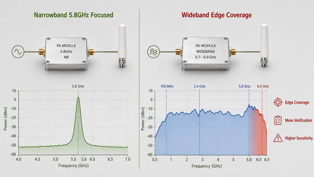
7. Why Do Wideband and Narrowband PAs Behave Differently?
Wideband and narrowband PAs behave differently because RF Power Amplifier Output Power at 5.8GHz depends on whether the module is optimized around that band, covering it as part of a wider range, or operating near a band edge. A narrowband 5.8GHz PA may be tuned tightly for that range, while a wideband PA must balance multiple frequency sections.
What’s the real story? Wideband is not automatically weaker, and narrowband is not automatically better. The right architecture depends on frequency priority, installation space, power target, cooling, supply reserve, antenna plan, and test evidence.
What Should Architecture Review Compare?
If the system covers both 900MHz and 5.8GHz, do not assume one module architecture will behave the same across both ends. You need evidence at the actual high-frequency operating point.
Compare:
- Is 5.8GHz optimized or only covered?
- Is 5.8GHz near a wideband edge?
- Does output flatness remain acceptable?
- Does heat rise faster at 5.8GHz?
- Does the antenna path differ by band?
- Does the test report include 5.8GHz-specific data?
- Is separate narrowband architecture more suitable for a critical channel?
How Should Full-Band Evidence Be Used?
Full-band evidence should show whether the high-frequency band remains stable across frequency, load, current, voltage, temperature, and protection status. For broader evidence, verified wideband RF Power Amplifier performance should include high-frequency output, load condition, voltage, current, temperature, and alarm behavior.
Key Takeaway: Architecture choice should be based on how 5.8GHz behaves under real system conditions, not on whether a module is simply labeled wideband or narrowband.
| Architecture Option | Trade-Off |
|---|---|
| Narrowband 5.8GHz PA | Stronger focus, less frequency flexibility |
| Wideband PA | More coverage, needs full-band evidence |
| Multi-module approach | Better band separation, more cabinet complexity |
| Shared antenna path | Compact layout, higher path interaction risk |
| Separate antenna paths | Cleaner band control, more routing work |
This table helps engineers evaluate architecture as a system trade-off rather than a catalog preference.
8. How to Judge RF Power Amplifier Output Evidence
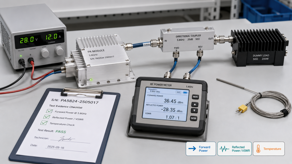
Test evidence should verify 5.8GHz output by recording RF Power Amplifier Output Power at a clear measurement boundary under known load, voltage, current, temperature, duty-cycle, VSWR, and protection-status conditions. A single peak wattage reading is not enough when high-frequency output is sensitive to path loss, heat, antenna match, and setup differences.
The better check is simple: use the test evidence to answer where the drop occurs and why it occurs. PA-port data, cabinet output, feeder-end reading, and antenna-port power each answer a different engineering question. Mixing them together creates confusion during acceptance and field retesting.
What Should the Test Record Include?
A useful 5.8GHz test record should make the result repeatable. It should let the buyer, supplier, and field engineer compare the same boundary instead of arguing over one isolated wattage number.
Record these items:
- Measurement reference point
- 5.8GHz frequency point or sweep range
- Load type and antenna condition
- Feeder length and connector path
- Supply voltage and current
- Temperature and test duration
- Duty cycle or operating mode
- Forward power and reflected power
- VSWR status
- Temperature, voltage, and current alarms
- Serial-number-linked test evidence
If 5.8GHz output changes after connecting the field antenna, engineers should review RF Power Amplifier VSWR protection and antenna mismatch before judging the module alone.
How Does Protection Feedback Help Diagnosis?
Protection feedback is not only there to protect the module. It also helps engineers locate the cause of the 5.8GHz drop. VSWR feedback can point toward antenna mismatch or connector reflection. Temperature feedback can show thermal derating. Voltage feedback can show supply weakness under high-load operation.
For RF SKYPOWER, this is where source-factory engineering support becomes useful. Module-side output data, protection status, 28V DC behavior, thermal condition, and RF path assumptions can be tied into one repeatable review instead of leaving the customer to compare factory data and field data without a common boundary.
Key Takeaway: Strong 5.8GHz evidence proves the test boundary, load condition, thermal state, supply status, and protection behavior, not only the highest power reading.
| Weak Evidence | Better Evidence |
|---|---|
| One 5.8GHz wattage number | Boundary-defined output record |
| PA-port data only | PA-port and antenna-port comparison |
| No load detail | Dummy load or antenna condition recorded |
| No thermal data | Temperature and duration included |
| No alarm record | VSWR and protection status shown |
| No S/N link | Unit-level repeatable evidence |
This table helps customers judge whether the evidence supports real field use or only a short bench result.
9. What RF Power Amplifier Output Data Buyers Need
Buyers should share 5.8GHz target boundary, antenna location, feeder path, connector count, duty cycle, temperature, supply condition, and acceptance method because RF Power Amplifier Output Power cannot be quoted correctly from “5.8GHz 100W” alone. That phrase does not tell the supplier whether the target is at the PA port, cabinet output, feeder end, or antenna input.
This is where procurement teams can prevent later disputes. A better RFQ gives the supplier enough context to judge whether the requested high-frequency output is realistic after installation.
What Belongs in a 5.8GHz RFQ?
The RFQ does not need perfect final drawings at the first discussion. Estimated routing, target boundaries, and operating conditions are already useful.
Share these items before quotation:
- Is 5.8GHz a required or optional band?
- Is the target at PA port, cabinet output, feeder end, or antenna input?
- Should 900MHz and 5.8GHz have the same antenna-port target?
- Will the system use wideband or narrowband PA modules?
- Where will antennas be installed?
- What feeder length and cable type are expected?
- How many connectors, adapters, protectors, or joints are in the path?
- What duty cycle and runtime are expected?
- What is the highest cabinet or ambient temperature?
- What supply voltage is available at the module under load?
- What VSWR, temperature, voltage, or current feedback is required?
- What test report format is needed for acceptance?
Why Is “5.8GHz 100W” Not Enough?
“5.8GHz 100W” is not enough because it does not define the reference point. A PA-port 100W requirement is different from an antenna-port 100W requirement after feeder, connector, antenna, and environmental conditions are included.
Key Takeaway: A good RFQ defines 5.8GHz as a system requirement, not just a frequency and wattage request.
| RFQ Item | Why It Matters |
|---|---|
| Target output point | Defines what “100W” means |
| Antenna path | Predicts high-frequency loss |
| Connector count | Shows transition risk |
| Duty cycle | Affects heat and stability |
| Temperature | Changes sustained output margin |
| Test boundary | Prevents acceptance confusion |
This table helps buyers move from a vague wattage request to an engineering-ready quotation.
10. What RF Power Amplifier Output Means at Antenna Port
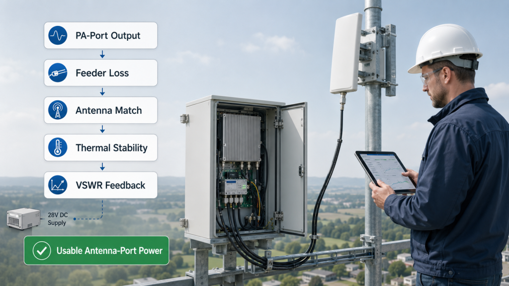
5.8GHz output is enough only when RF Power Amplifier Output Power remains usable at the required system boundary after feeder loss, connector loss, antenna match, thermal load, supply behavior, duty cycle, protection logic, and test evidence are included. The answer is not a fixed wattage. It depends on what the installed C-UAS system needs and where that power must remain.
Here’s the final decision point: do not solve every 5.8GHz drop by buying a larger PA first. Sometimes the better correction is shorter feeder routing, better cable grade, fewer transitions, improved antenna matching, stronger cooling, stable 28V supply, or a clearer acceptance boundary.
What Decision Path Works Best?
Use a step-by-step review before approving the module. This keeps the discussion focused on delivered output, not only catalog output.
Check in this order:
- Confirm whether 5.8GHz is mission-critical
- Define the required output boundary
- Verify PA-port 5.8GHz output under controlled load
- Check whether 5.8GHz is optimized or edge-covered
- Review feeder length, cable grade, and connector path
- Test with the real or equivalent antenna condition
- Record VSWR and reflected power behavior
- Confirm thermal stability under expected duty cycle
- Confirm module-end voltage under full load
- Compare test evidence with field acceptance requirements
What Should Be Optimized Before Oversizing the PA?
A larger PA can sometimes help, but it should not be the automatic first response. If the real problem is feeder loss, connector transitions, antenna mismatch, thermal derating, or unclear measurement boundaries, simply increasing PA output may add heat and supply pressure without solving the cause.
As an RF Power Amplifier module and C-UAS core component source factory, RF SKYPOWER can help customers review 5.8GHz target power, 900MHz comparison, antenna distance, feeder loss, wideband or narrowband architecture, duty cycle, temperature, protection feedback, and test boundary before final approval.
Key Takeaway: 5.8GHz output is enough when the installed RF chain can deliver the required antenna-port power under the real operating conditions of the project.
| If the Problem Is… | Start With… |
|---|---|
| PA-port output is weak | Module output and drive condition |
| Antenna-port output is low | Feeder, connector, and antenna path |
| Output falls after minutes | Thermal and duty-cycle review |
| VSWR rises after antenna connection | Antenna mismatch and mounting condition |
| Factory and field data conflict | Measurement boundary comparison |
| Higher PA creates new alarms | Thermal, supply, and protection review |
This table helps engineers choose the right correction path before oversizing the PA or blaming the wrong subsystem.
FAQ
Can I assume 5.8GHz output will match 900MHz output?
No. 5.8GHz should be verified separately because amplifier behavior, matching, feeder loss, connector transitions, antenna VSWR, thermal margin, and measurement boundaries can differ from 900MHz.
What should I check before buying a 5.8GHz PA module?
Start with the required output boundary, frequency priority, feeder length, connector count, antenna location, duty cycle, cabinet temperature, supply voltage, VSWR feedback, and test evidence. A wattage label alone is not enough for high-frequency approval.
How do I know if 5.8GHz output drop is caused by the module?
Compare PA-port output with cabinet output, feeder-end power, and antenna-port power under the same frequency, load, temperature, and duty-cycle conditions. If the PA-port result is stable but antenna-port power falls, the installed RF chain needs closer review.
Should I choose narrowband or wideband for 5.8GHz?
Choose based on frequency priority and system architecture. A narrowband PA may focus more tightly on 5.8GHz, while a wideband PA offers more frequency coverage but needs full-band output and thermal evidence near the high-frequency point.
When should 5.8GHz be tested at the antenna port?
Test 5.8GHz at the antenna port when field acceptance depends on installed system output, not only module capability. This is especially important for long feeder paths, rooftop antennas, guard towers, high-temperature cabinets, or strict retest requirements.
Conclusion
RF output at 5.8GHz should not be judged with the same assumptions used at 900MHz. This article solved the practical engineering question behind high-frequency output drop: whether the installed RF chain can preserve enough usable antenna-port power after amplifier behavior, matching sensitivity, PCB path, connector transitions, feeder loss, antenna VSWR, thermal margin, supply stability, and measurement boundaries are included.
For system integrators, RF engineers, and procurement reviewers, the decision path is clear. Define the measurement point before judging a 5.8GHz drop, then compare PA-port output, cabinet output, feeder-end power, antenna-port power, cable path, connector count, antenna match, duty cycle, ambient temperature, module-end voltage, VSWR status, and repeatable test evidence.
As an RF Power Amplifier module and C-UAS core component source factory, RF SKYPOWER supports 5.8GHz output evaluation by reviewing high-frequency RF chain loss, wideband or narrowband architecture, antenna distance, 28V DC supply behavior, thermal margin, protection feedback, and repeatable test reports before final project approval. If your prison or high-security C-UAS project has not confirmed 5.8GHz antenna-port power, feeder loss, thermal margin, and protection status, you can contact us today to review the RF path before final approval.
Field-ready C-UAS systems are built on verified high-frequency output, not assumptions copied from lower-band performance.