










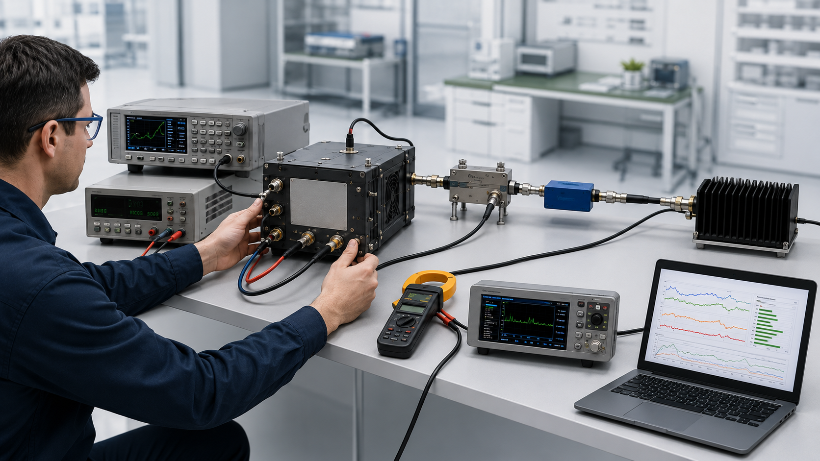
RF PA alarm thresholds are useful only when another engineer can reproduce the condition that caused a warning, output foldback, shutdown, latched fault, or recovery. A list of threshold values without sensing location, test condition, protection response, applicable tolerance, version identity, and traceability cannot support formal acceptance.
The threshold definition and the verification record should remain separate. One approved threshold set may apply to a model, hardware revision, or firmware version. The acceptance plan then defines which trigger, response, and recovery checks must be completed per S/N, per sample, or per production batch.
This article covers temperature, VSWR or reflected-power, voltage, current, alarm status, shutdown, latch, reset, and recovery evidence. It does not replace full RF PA protection-logic verification, control-interface mapping, antenna-path troubleshooting, or complete test-report review.
The acceptance decision should connect:
Alarm boundary → Test condition → Measured trigger → Protection response → Recovery behavior → Applicable version and S/N
1. What an RF PA Alarm Threshold File Must Prove
An acceptance-ready alarm threshold file should allow the buyer, test engineer, and system integrator to understand what the module monitors and what happens when an abnormal condition reaches a controlled boundary.
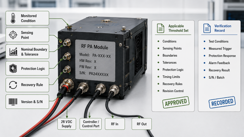
It should answer six questions:
- Which abnormal condition is monitored?
- Where is the condition sensed or measured?
- Which nominal boundary, tolerance, and timing limit apply?
- What warning or protection response occurs?
- How does the module recover after the condition clears?
- Which hardware, firmware, threshold-set revision, batch, and S/N does the record cover?
A file that states only:
- Temperature alarm: XX°C
- VSWR alarm: X.X:1
- Voltage alarm: XX V
- Current protection: XX A
does not provide enough information for repeatable acceptance.
Another engineer would still need to know:
- Whether temperature refers to an internal sensor, case point, baseplate, heatsink, or chamber ambient
- Whether voltage was measured at the power supply or the RF PA input
- Whether current applies during startup, standby, or active RF output
- Whether mismatch protection responds to VSWR, reflected power, detector voltage, or an internal state
- Whether the module warns, reduces output, shuts down, or latches
- Whether recovery is automatic or requires a reset
- Which tolerance, hysteresis, delay, and threshold revision apply
A threshold value becomes acceptance-ready only when the file defines the measurement point, operating condition, nominal boundary, allowable variation, protection response, and recovery rule.
Threshold Definition and Verification Record Are Different
The threshold definition describes the approved protection boundary.
It may be controlled at the:
- Model level
- Hardware-revision level
- Firmware or logic-version level
- Approved configuration level
The verification record shows whether the required behavior was confirmed under a defined condition.
It may apply to:
- One delivered S/N
- Selected production samples
- An approved batch-verification plan
- A qualification unit
- A Golden Sample comparison
The same threshold set may apply to several modules. This does not mean each module needs a different numerical threshold. It means the shipment evidence must identify which threshold set applies and which units or samples were verified.
When Reduced Per-Unit Verification May Be Acceptable
A reduced per-unit verification scope may be acceptable when:
- The module uses a previously approved threshold set.
- The hardware and firmware state remain unchanged.
- The production batch follows an approved sampling or verification plan.
- No relevant protection-path change has occurred.
- The threshold revision remains traceable to the delivered units.
- The project does not require a full trigger test on every S/N.
The documentation itself should remain complete.
It should still identify:
- Applicable threshold revision
- Hardware and firmware state
- Verification scope
- Tested samples or S/N units
- Production batch
- Test procedure
- Final acceptance decision
Reduced testing does not justify incomplete threshold documentation.
2. Which Alarm and Protection Boundaries Must Be Defined
The applicable boundaries depend on the approved RF PA design.
Not every module uses the same sensors, alarm outputs, protection stages, or recovery method. The file should document only the functions supported by the approved design.
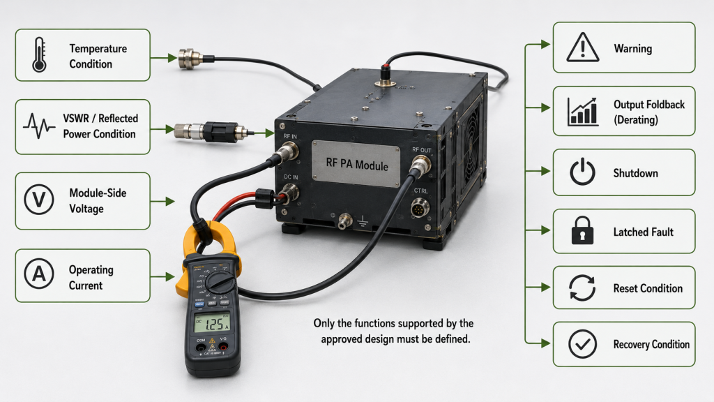
For each applicable condition, it should distinguish between:
- Warning
- Output foldback or derating
- Shutdown
- Latched fault
- Reset condition
- Recovery condition
Where relevant, it should also define:
- Nominal trigger value
- Acceptance tolerance
- Hysteresis
- Response delay
- Recovery delay
- Retry count
Temperature Boundaries
Where temperature protection is used, the file should identify the sensing point and applicable response.
Possible references include:
- Internal sensor
- Device-area sensor
- Case point
- Baseplate point
- Heatsink point
- Chamber ambient
These locations are not interchangeable.
A chamber temperature does not represent the same condition as an internal sensor or a defined case-temperature point.
The threshold set may distinguish:
- Temperature warning
- Output foldback or derating
- Shutdown
- Latched over-temperature fault
- Automatic recovery
- Manual reset
- Recovery temperature
The warning, shutdown, and recovery values may differ because of hysteresis and protection sequencing.
VSWR or Reflected-Power Boundaries
The file should use terminology that matches the actual module design.
Some modules may report VSWR. Others may respond to:
- Forward and reflected detector levels
- Reflected power
- Detector voltage
- Coupler output
- An internally calculated mismatch state
A general acceptance file should therefore refer to the:
VSWR or reflected-power alarm condition
where the exact detection method depends on the design.
The file should define, where applicable:
- Forward-power state
- Reflected-power or mismatch boundary
- Measurement reference
- Warning behavior
- Foldback behavior
- Shutdown or latch condition
- Response delay
- Recovery or reset method
- Approved load or mismatch test condition
A statement such as “VSWR protection available” does not prove when protection begins or what the module does after the boundary is reached.
Voltage Boundaries
Voltage protection should identify the sensing point.
It may refer to:
- RF PA module input
- Power-supply output
- Internal monitored rail
- Control-board supply
- Another approved measurement point
The file may distinguish:
- Undervoltage warning
- Undervoltage shutdown
- Overvoltage warning
- Overvoltage shutdown
- Startup inhibit
- Restart condition
- Recovery delay
A voltage shown on the power supply does not prove that the same voltage exists at the RF PA input after cable, connector, and harness loss.
Current Boundaries
Current protection should be connected to the operating state.
The file should identify:
- Measurement boundary
- Frequency or frequency range
- RF input drive
- RF output state
- Duty condition
- Nominal current boundary
- Acceptance tolerance
- Foldback or shutdown response
- Recovery method
Startup current, standby current, and active RF current are different conditions. One current value without operating context is not suitable for acceptance.
Alarm Status, Latch, Reset, and Recovery
The threshold file should state how the fault becomes visible to the system.
Where applicable, it should define:
- Alarm code
- Alarm pin
- Active-high or active-low state
- Serial status message
- Fault-specific or general alarm
- Latched or non-latched behavior
- Automatic reset
- Manual reset
- Power-cycle requirement
- Recovery delay
- Retry count
The physical alarm output and its system meaning should remain consistent with the approved RF PA control interface.
Do Not Apply One Universal Numerical Boundary
Threshold values should come from the approved module specification, protection design, hardware or firmware state, and project acceptance plan.
One universal numerical boundary should not be applied across different:
- Frequency bands
- Power classes
- Thermal structures
- Sensor locations
- Control boards
- Firmware versions
- Cooling conditions
The purpose of the file is not to impose one generic number. It is to make the approved boundary and acceptance range reproducible.
3. What Test Conditions Make Threshold Values Reproducible
A threshold cannot be verified independently from the condition used to reach it.
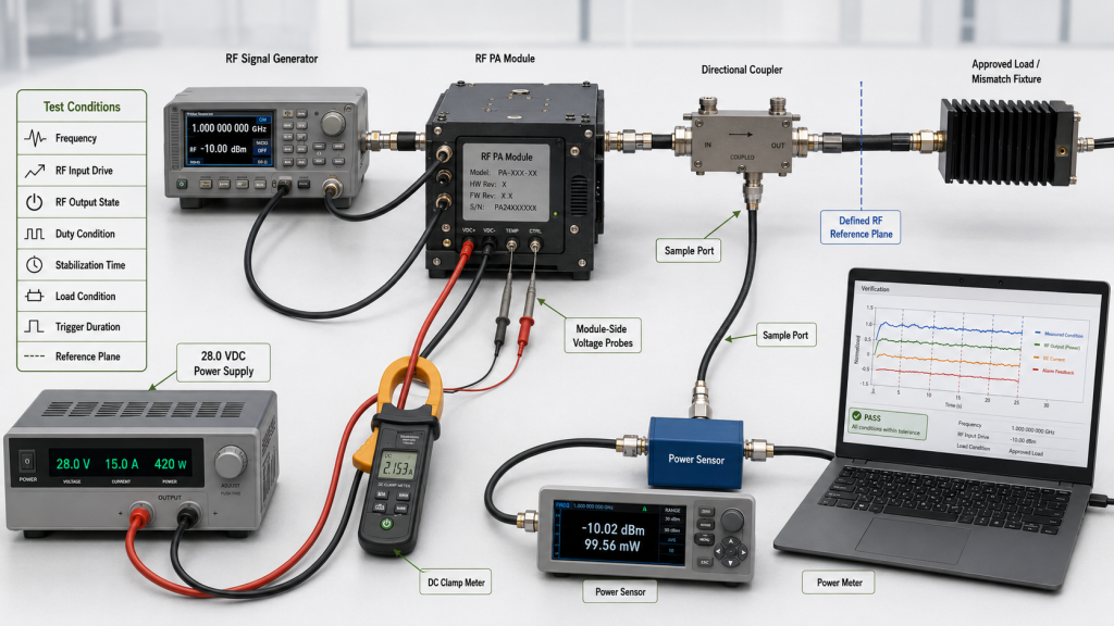
The file should include enough information for another engineer to understand and repeat the approved verification boundary.
RF Operating Condition
The record should identify, where applicable:
- Frequency or tested frequency range
- RF input drive
- RF output state
- Continuous, pulsed, or other duty condition
- Test duration
- Startup or thermally stabilized state
- Forward and reflected condition
- Load condition
A temperature trigger measured at low output may not represent operation near the required RF power.
An overcurrent result at one frequency may not represent current behavior across a wide operating band.
DC Condition
The record should identify:
- Module-side DC voltage
- DC current
- Power-supply setting
- Startup or steady-state condition
- Cable or harness condition where relevant
The module-input voltage is normally more useful than a remote power-supply display when voltage drop can occur between the supply and the RF PA.
Thermal Condition
The file should define:
- Ambient temperature
- Chamber condition, where used
- Sensor or temperature reference point
- Initial temperature
- Stabilization time
- Temperature at trigger
- Peak temperature
- Temperature at recovery
A single temperature number cannot show whether the value came from ambient air, a heatsink, the RF PA case, or an internal sensor.
Load or Reflection Condition
For VSWR or reflected-power verification, the file should identify:
- Approved fixture or method
- Load condition
- Forward-power level
- Reflected-power state
- Reference plane
- Mismatch duration
- Protection response
- Recovery condition
The result should not depend on an undocumented cable arrangement, loose connector, or uncontrolled antenna mismatch.
Time-Related Conditions
Where applicable, the file should include:
- Debounce time
- Warning delay
- Foldback delay
- Shutdown delay
- Fault-latch time
- Retry delay
- Recovery delay
Two engineers can observe the same measured value but report different behavior when timing limits are not defined.
Applicable Version
The test evidence should identify:
- Model number
- Hardware revision
- PCB revision, where applicable
- Firmware or logic version
- Threshold-set revision
- Test-procedure revision
- Production batch
- Tested S/N
The final threshold evidence should remain aligned with the version-controlled RF PA test report used for shipment review.
4. How to Verify Trigger, Response, and Recovery
This section should review whether the file contains a complete evidence sequence. It should not replace the detailed protection test procedure.
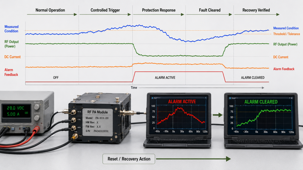
Evidence Sequence the File Should Contain
The threshold file should show:
- The approved normal operating condition
- The controlled abnormal condition and approved test method
- The measured value at the defined sensing or reference point
- The observed warning, foldback, shutdown, or latch response
- The controller-visible alarm or status result
- The condition used to clear the fault
- The automatic recovery, reset, or power-cycle result
- The applicable threshold revision, procedure, batch, and tested S/N
Judge the Result Against an Acceptance Band
A measured trigger does not need to equal one nominal number with zero deviation.
The acceptance file should define, where applicable:
- Nominal boundary
- Trigger tolerance
- Sensor tolerance
- Detector or ADC tolerance
- Test-equipment uncertainty
- Hysteresis
- Response-time limit
The result should be judged against the approved acceptance range rather than an undocumented exact value.
For example, a complete record should show whether:
- The measured trigger remained within tolerance.
- Hysteresis remained within the approved range.
- The alarm or shutdown occurred within the required response time.
- Recovery occurred within the defined condition and delay.
Verify the Trigger Evidence
The file should show:
- Which condition changed
- Where it was measured
- The measured trigger value
- The approved tolerance
- The trigger delay
- The observed result
An alarm screenshot without the corresponding measured condition is weak evidence.
Verify the Protection Response
The file should state what happened after the trigger.
Possible responses may include:
- Warning only
- Output foldback or derating
- RF mute
- Shutdown
- Input inhibit
- Latched fault
- Retry sequence
The response should be supported by measurable evidence such as:
- RF output change
- DC current change
- Alarm-state change
- Control response
- Protection status
- Shutdown state
Verify Controller-Visible Feedback
The module may protect itself while the controller receives the wrong status.
The evidence should therefore confirm:
- Correct alarm mapping
- Correct polarity
- Correct fault code
- Correct communication response
- Correct latch state
- Correct reset acknowledgment
This is especially important when several faults share one general alarm output.
Verify Recovery
The record should show:
- Which condition cleared the fault
- Which recovery boundary applied
- Whether hysteresis was observed
- Whether recovery was automatic
- Whether a reset or power cycle was required
- How long recovery took
- Whether RF output returned normally
- Whether the alarm cleared correctly
A correct trigger without the expected recovery does not complete the protection evidence.
Safety Boundary
Protection verification should use an approved fixture and controlled method.
The threshold file should reference the approved procedure rather than encouraging uncontrolled over-temperature, overvoltage, overcurrent, or high-reflection testing on a powered RF PA.
5. How Version, Threshold Set, and S/N Evidence Must Stay Aligned
An alarm threshold file may contain technically valid values but still fail acceptance when it belongs to the wrong module state.
The traceability chain should remain:
Approved module state → Hardware version → Firmware or logic version → Threshold-set revision → Test condition → Production batch → Module S/N → Acceptance record
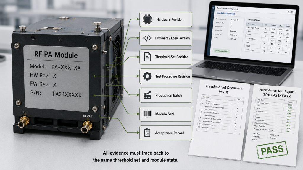
Changes That Require Threshold-File Review
The threshold file should be reviewed when a change can affect trigger detection, protection response, status reporting, or recovery.
Examples include changes to:
- Sensor or detector
- Sensor location
- Control board
- Firmware or protection logic
- RF detector path
- Voltage or current sensing
- Alarm mapping
- Reset or recovery behavior
- Thermal-interface condition
- Harness or connector affecting sensing
- Ground reference
- Relevant component source
- Test fixture or procedure
A formatting change may need only document revision control.
A technical change that affects the sensing point, nominal boundary, tolerance, response, or recovery requires appropriate validation.
The full supplier-change or process-change review belongs in its dedicated control record. The alarm threshold file only needs to show whether the approved threshold set and verification evidence remain applicable.
S/N and Batch Alignment
The threshold definition may be controlled at model or version level.
The verification record should show:
- Which S/N units were tested
- Which production batch was represented
- Whether testing was per unit, per sample, or per batch
- Which threshold revision applied
- Which procedure was used
- Which result supported acceptance
This prevents the buyer from receiving:
- A threshold file for an earlier hardware version
- An alarm screenshot from another module
- A generic protection statement without test identity
- A batch claim without sample identification
- A report that cannot be linked to the delivered units
Threshold evidence should form part of the complete S/N-linked RF PA acceptance checklist.
6. What Evidence Supports PASS, RETEST, or HOLD
The threshold-file review should end with a clear acceptance decision.
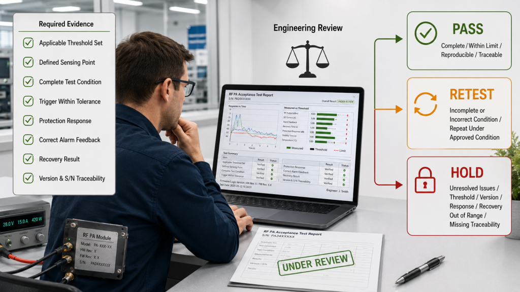
PASS
Use PASS when:
- The applicable threshold set is identified.
- The sensing or measurement point is defined.
- The operating and test conditions are complete.
- The measured trigger remains within the approved tolerance.
- Hysteresis and response time remain within applicable limits.
- The protection response is recorded.
- Alarm or status feedback is correct.
- Recovery behavior matches the approved logic.
- Hardware and firmware versions are aligned.
- Required batch and S/N evidence is traceable.
RETEST
Use RETEST when:
- The measured trigger is inconsistent.
- The measurement point is unclear.
- The approved tolerance or timing limit was not applied.
- The test condition is incomplete.
- The protection response cannot be reproduced.
- Alarm feedback is intermittent.
- Recovery differs between attempts.
- The wrong load, frequency, voltage, output, or temperature condition was used.
- Additional repeatability evidence is required.
RETEST means the result may still become acceptable, but the check must be repeated under the approved boundary.
HOLD
Use HOLD when:
- The threshold set is missing or outdated.
- The file belongs to the wrong hardware or firmware version.
- The sensing point is unknown.
- The nominal boundary or tolerance is undefined.
- The protection response is not documented.
- Recovery or reset behavior is unresolved.
- The tested unit cannot be identified.
- The evidence cannot be linked to the production batch or delivered S/N.
- The measured result is outside the approved acceptance range.
A HOLD decision prevents incomplete protection evidence from being accepted only because the RF output test passed.
RF PA Alarm Threshold Acceptance Matrix
| Boundary | File Must Define | Verification Evidence | RETEST or HOLD Trigger |
|---|---|---|---|
| Temperature | Sensor point, nominal boundary, tolerance, warning, foldback or shutdown, hysteresis, and recovery | Measured temperature, RF output, response time, alarm state, and recovery result | Unknown sensor point, missing tolerance, wrong revision, or response outside limits |
| VSWR or reflected power | Reference condition, nominal trigger, tolerance, protection response, timing, and recovery | Forward/reflected condition, alarm state, RF output response, and reset result | Undefined load condition, unknown reference, or alarm without measurable boundary |
| Voltage | Module-side sensing point, nominal limits, tolerance, shutdown or inhibit behavior, and recovery | Module-input voltage, operating state, alarm output, and restart result | Power-supply display used without module-side evidence or wrong operating state |
| Current | Measurement boundary, frequency, output state, duty condition, nominal limit, tolerance, and protection response | Measured current, RF output condition, alarm response, and recovery | Current limit lacks RF condition, timing, or defined measurement point |
| Status and recovery | Fault code, polarity, latch state, reset method, recovery delay, and retry rule | Controller-visible status, reset acknowledgment, and repeated recovery result | Generic alarm, incorrect mapping, unknown reset rule, or inconsistent recovery |
The matrix should be adapted to the actual functions of the approved module. It should not be used to claim unsupported protection features.
RFQ: What Buyers Should Define for Alarm Threshold Evidence
A buyer should define the required alarm evidence before final acceptance rather than requesting an unspecified protection file after testing is complete.
The RFQ should ask:
- Which warning, foldback, shutdown, latch, and recovery boundaries apply?
- Where is each temperature, voltage, current, or reflected-power condition measured?
- What nominal value, tolerance, hysteresis, and response-time limit apply?
- Which hardware, firmware, and threshold-set revision applies?
- Which frequency, RF output, duty, load, voltage, and temperature conditions are used?
- What alarm or status does the controller receive after each trigger?
- Which checks are completed per S/N, per sample, or per production batch?
- What conditions require retesting or an updated threshold file?
The RFQ should also define:
- Required frequency range
- RF input and output state
- Duty condition
- Module-side DC voltage
- Load or mismatch boundary
- Ambient and sensor temperature points
- Warning and protection responses
- Latch and reset behavior
- Recovery delay
- Controller feedback
- Verification scope
- Report format
- S/N traceability
- Final acceptance authority
A useful supplier response should explain:
- Which alarm functions are supported
- Which threshold set applies
- Which sensing point is used
- Which acceptance tolerance applies
- What the RF PA does after the trigger
- How the controller receives the fault
- How recovery occurs
- How the evidence is connected to the delivered units
Statements such as “protection included,” “alarm tested,” or “threshold normal” do not provide enough evidence for formal acceptance.
Conclusion
An RF PA alarm threshold file should do more than list several protection values.
It should allow another engineer to verify:
- The monitored condition
- The sensing or measurement point
- The nominal boundary and tolerance
- The trigger and response timing
- The protection response
- The controller-visible alarm
- The latch or reset state
- The recovery behavior
- The applicable hardware and firmware state
- The required batch and S/N evidence
The final evidence chain should remain:
Threshold-set revision → Defined test condition → Measured trigger → Protection response → Status feedback → Recovery result → Batch and S/N traceability
The threshold definition may apply to an approved model or version. The verification record should show whether the required behavior was confirmed for the delivered unit, selected samples, or approved production batch.
The final decision should remain clear:
- PASS when the evidence is complete, within limits, reproducible, and traceable.
- RETEST when a result must be repeated under the approved condition.
- HOLD when the threshold set, tolerance, version, response, recovery, or traceability remains unresolved.
For projects requiring custom RF power amplifier modules, RF SKYPOWER can align alarm and protection evidence with the required frequency, RF output state, duty condition, load boundary, DC input, control interface, hardware or firmware version, and S/N-linked acceptance plan.
Submit the required alarm types, nominal boundaries, tolerances, sensing points, test conditions, controller feedback, reset and recovery rules, per-unit or batch verification scope, report format, and traceability requirements through our engineering RFQ.