










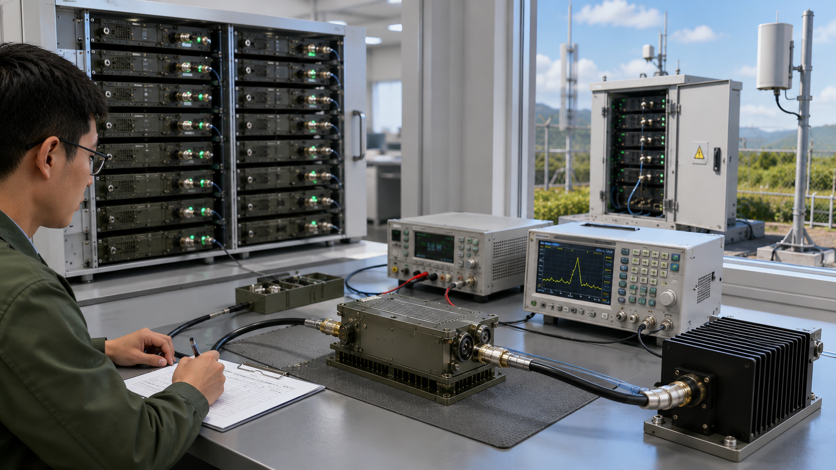
RF output after burn-in should be verified on the same unit before shipment. A completed and traceable burn-in record can show that the RF Power Amplifier survived the defined electrical and thermal stress without prohibited interruption or intervention. It does not prove that output, gain, current, temperature behavior, reflected-power margin, and protection status still meet the shipment limits.
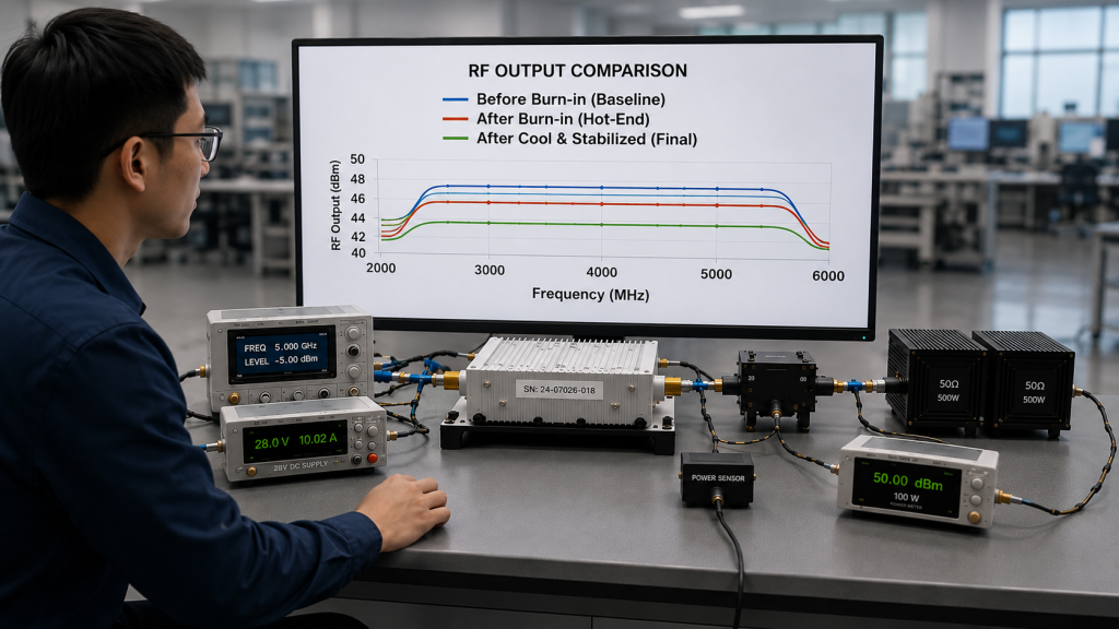
When reviewing RF Power Amplifier Modules for shipment, the final question is not only whether the aging period was completed. It is whether the delivered module still meets its RF performance requirement after burn-in and whether the pre-burn-in, hot-end, and final stabilized results are technically comparable.
A valid decision requires traceable unit identity, controlled RF input, consistent frequency and timing conditions, a defined measurement reference plane, comparable DC and thermal boundaries, documented measurement corrections, and a pass-or-fail rule agreed before testing. Without these controls, an apparent output change may come from the test process rather than the PA.
1. Why a Burn-In Pass Does Not Prove Final RF Output
Burn-in is intended to expose early failures and unstable behavior under a defined operating stress. Depending on the project, the process may include:
- Continuous or high-duty RF operation
- Elevated module or cabinet temperature
- Repeated startup and shutdown
- Multi-frequency or multi-channel operation
- Sustained DC current
- Alarm and protection monitoring
- A project-defined operating duration
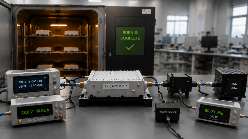
A completed burn-in record may show that the unit remained operational throughout the approved process. It does not automatically prove that the unit still delivers the same RF performance afterward.
The distinction is important:
- Burn-in evidence shows what stress was applied and whether prohibited events occurred.
- Hot-end RF evidence shows performance at or immediately after the end of the burn-in stress.
- Final stabilized RF evidence shows whether the unit meets the shipment specification after the defined cooling and restabilization period.
- Shipment acceptance evidence connects all results to the same model, serial number, version state, and decision rule.
The complete RF Power Amplifier batch burn-in process should define the operating stress, duration, load, voltage, cooling, interruption rules, and monitoring conditions. This article begins with the RF comparison required after that process.
Why Hot-End and Final Results Must Be Separated
A measurement taken while the PA is still hot answers a different question from a measurement taken after cooling.
The hot-end result can reveal:
- Output reduction under accumulated heat
- Higher current
- Thermal foldback
- Alarm or shutdown activity
- Reduced reflected-power margin
- Performance at the end of sustained stress
The cooled and restabilized result can reveal:
- Whether output returns to the original range
- Whether a gain or output change remains
- Whether the change was reversible
- Whether the final shipment specification is still met
A hot-end output reduction does not automatically prove permanent aging damage. A restored cooled result also does not erase a prohibited hot-state event that occurred during burn-in.
The test report must identify which result is used for:
- Burn-in process review
- Hot-state performance review
- Final shipment acceptance
What Burn-In May Reveal
A module may complete burn-in without an immediate shutdown but still show:
- Lower output at one or more frequencies
- Higher RF input drive required for the same output
- Gain drift
- Higher DC current
- Different case or baseplate temperature
- Increased reflected power
- Reduced VSWR margin
- Protection foldback
- Irregular alarm behavior
- A result that cannot be repeated
These symptoms do not all indicate the same failure path. The recheck must compare more than one wattage reading.
2. What Must Stay Controlled Before and After Burn-In
A pre- and post-burn-in difference should not be classified as RF performance drift until the comparison conditions have been verified.
The tests should use the same or technically equivalent:
- Unit model and serial number
- Hardware revision
- Firmware or control version
- RF enable and protection configuration
- Frequency points and test order
- Dwell and settling time
- RF waveform and occupied bandwidth
- RF input level
- Automatic level control status
- Output reference plane
- RF load and VSWR condition
- PA-terminal voltage
- Cooling arrangement
- Stabilization rule
- Measurement method
- Correction method
- Measurement uncertainty
- Pass-or-fail decision rule
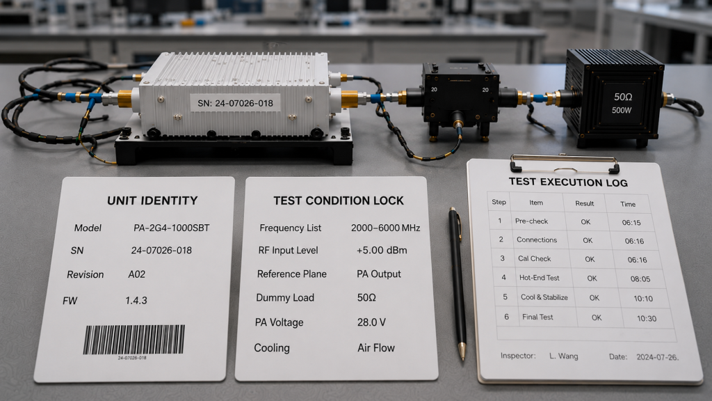
If one of these conditions changes, the difference may describe two test configurations rather than a change in the PA.
Pre-Burn-In vs Post-Burn-In Comparison Controls
| Comparison Item | Required Control | Risk If It Changes |
|---|---|---|
| Unit identity | Same model, S/N, hardware, and firmware state | Results may describe different unit states |
| RF input | Same waveform, bandwidth, Pin, and ALC condition | Higher drive may hide gain drift |
| Frequency sequence | Same points, order, direction, dwell, and settling time | Thermal accumulation may change the result |
| Reference plane | Same PA port or other defined point | RF-path loss may appear as PA drift |
| RF load | Same dummy load or defined load condition | VSWR changes may alter output |
| DC condition | Same PA-terminal voltage range | Voltage loss may appear as aging drift |
| Thermal condition | Defined hot-end, cooling, and restabilization states | Reversible thermal behavior may be misclassified |
| Measurement chain | Same or proven-equivalent calibrated method | Instrument or path differences may create false drift |
| Acceptance rule | Same limits, uncertainty treatment, and guard band | Pass or fail becomes subjective |
The Same Equipment Is Preferred, but Equivalence Can Be Proven
Using the same equipment and RF path before and after burn-in reduces comparison risk.
When different equipment must be used, the report should document:
- Calibration traceability
- Compatible measurement method
- Equivalent path-correction logic
- Measurement uncertainty
- Cross-check results between the two chains
- Any offset applied during comparison
A new power meter with valid calibration is not automatically equivalent to the original measurement chain. Equivalence must be supported by evidence.
Keep the RF Input Condition Visible
A stable output reading does not always mean that PA behavior remained unchanged.
If automatic level control or an engineer increases RF input drive after burn-in, the output may remain constant even when:
- PA gain has decreased
- More driver margin is required
- The PA operates deeper in compression
- Driver-stage current increases
- System efficiency changes
The report should record:
- Pre-burn-in RF input level
- Hot-end RF input level
- Final stabilized RF input level
- Whether input drive remains fixed
- Whether ALC is enabled
- Any manual or automatic adjustment
- Gain or required-drive change
Constant output achieved only through increased drive should not be reported as unchanged PA performance.
Gain comparison must use compatible input- and output-power definitions. Large-signal gain near compression should not be treated as equivalent to small-signal gain.
3. How to Run the Post-Burn-In RF Recheck
The recheck should reproduce the approved baseline while separating the hot-end result from the final stabilized result.
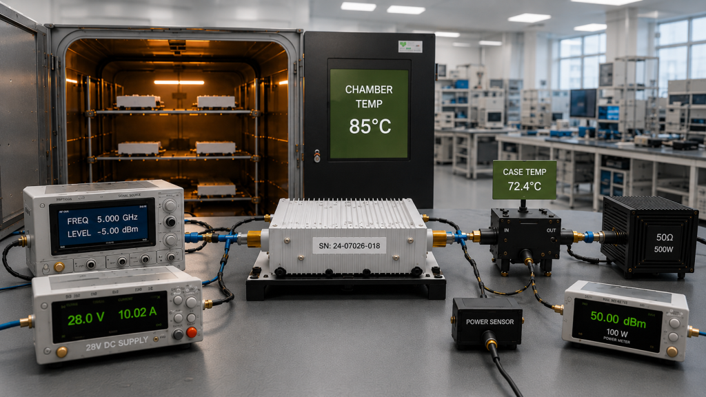
Step 1: Confirm the Unit and Burn-In Record
Before applying RF power, verify:
- Product model
- Serial number
- Hardware revision
- Firmware or control version
- Bias and control state
- Alarm and protection settings
- Associated burn-in record
The burn-in record should state:
- Planned duration
- Actual accumulated operating time
- Waveform and duty cycle
- Frequency or operating sequence
- RF load
- PA-terminal voltage
- Cooling and temperature conditions
- Alarm and protection events
- Power or RF interruptions
- Automatic restarts
- Manual resets
- Operator intervention
- Paused or repeated test segments
A nominal 72-hour record does not prove 72 hours of valid accumulated operation when the test included undocumented interruptions or resets.
Step 2: Capture the As-Burned State Before Adjustment
When the project requires evidence of burn-in-induced change, record the as-burned result before performing:
- Bias adjustment
- RF tuning
- Matching adjustment
- Input-drive compensation
- Calibration-value change
- Firmware update
- Control-parameter change
- Mechanical or thermal rework
The report should distinguish:
- Pre-burn-in baseline
- As-burned hot-end result
- Cooled and restabilized result before adjustment
- Final result after an authorized adjustment or rework
Any adjustment should be recorded with:
- Time and reason
- Changed parameter
- Before-adjustment result
- After-adjustment result
- Approval authority
- Required retest
- Required partial or full repeated burn-in
A tuned result should not replace the original as-burned evidence.
Step 3: Confirm the Measurement Chain
Use a calibrated RF path suitable for the expected power level.
A typical setup may include:
- RF signal generator or SDR source
- RF Power Amplifier
- Directional coupler
- 50 Ω dummy load
- Power sensor
- Power meter
- Attenuator or analyzer path when required
Document:
- Equipment identification
- Calibration validity
- Cable and connector loss
- Coupler coupling factor
- Attenuator value
- Sensor correction
- Total path correction
- Measurement uncertainty
A changed correction value may create an apparent output shift even when PA behavior has not changed.
Step 4: Control Frequency Order and Dwell Time
The same frequency list is not sufficient when test order, dwell time, or accumulated heating differs.
The pre- and post-burn-in tests should define:
- Frequency points or sweep range
- Sweep direction
- Frequency order
- Dwell time at each point
- Settling time before recording
- Delay between points
- Continuous sweep or point-by-point method
- Thermal state at each measurement point
Testing a band-edge frequency first in one test and last in another may produce different thermal conditions.
A full-power swept RF PA test is useful when the shipment requirement applies across a frequency range. The same sequence and timing logic should be used when the purpose is a direct pre- and post-burn-in comparison.
Step 5: Reproduce the RF, DC, and Thermal Conditions
Record:
- CW or modulation type
- Occupied bandwidth
- Peak-to-average power ratio when relevant
- Average, peak, or peak envelope power definition
- RF input level
- ALC state
- PA-terminal voltage
- DC current
- Ambient temperature
- Case or baseplate temperature
- Cooling method
- Airflow condition
- Stabilization rule
The power-supply display alone is not sufficient. Voltage loss across the DC path may create a false post-burn-in output difference.
Step 6: Measure the Hot-End and Final Stabilized Results
At the end of burn-in, record the hot-end result before the unit cools beyond the defined hot-state boundary.
After the approved cooling and stabilization period, repeat the final comparison under the same normal-temperature reference conditions.
At each required frequency, record:
- RF input level
- RF output
- Gain
- PA-terminal voltage
- DC current
- Temperature
- Forward power
- Reflected power
- VSWR
- Alarm and protection status
The comparison should show whether a change is:
- Present only at hot state
- Still present after cooling
- Frequency-specific
- Related to input drive
- Related to voltage or current
- Related to load or protection
- Repeatable under the same setup
4. How to Judge Whether the Output Change Is Real
A reported difference should first be tested against the comparison controls.
Apparent Change Caused by the Test Process
The difference may not represent PA drift when:
- RF input drive changed
- ALC was enabled in only one test
- Frequency order or dwell time changed
- The output reference plane changed
- Path corrections changed
- RF load or VSWR changed
- PA-terminal voltage changed
- One result was hot and the other was cooled
- Measurement equipment changed without equivalence evidence
- Firmware, bias, or protection settings changed
- Adjustment was performed before the as-burned result was captured
Correct or document these differences before judging the PA.
Real RF Performance Change
A real change becomes more likely when:
- The same unit is tested
- Unit configuration remains traceable
- Comparable measurement chains are used
- RF input drive remains fixed
- Frequency timing and thermal states are controlled
- PA-terminal voltage and RF load remain within range
- The difference repeats
- Gain or required drive also changes
- The change remains after cooling and restabilization
Protection-Limited Output
A lower result may come from protection activity rather than permanent RF-stage degradation.
The RF Power Amplifier protection logic should be reviewed when output changes together with:
- Temperature alarm
- Voltage alarm
- Current alarm
- Reflected-power alarm
- VSWR protection
- Foldback
- Shutdown
- Reset or recovery activity
The report should state whether the response was expected, permitted, repeatable, and present only at hot state or also after cooling.
Define the Permitted Change Before Testing
The RFQ or test plan should define:
- Minimum absolute final output
- Permitted hot-end output behavior
- Maximum final change in watts
- Maximum final change in percentage
- Maximum final change in dB
- Frequency-specific limits
- Gain-change limit
- Current-change limit
- Temperature boundary
- Permitted alarm or foldback behavior
- Measurement uncertainty
- Guard-band and decision rule
A supplier should not create a new tolerance after seeing the result.
Final Decision Categories
Pass
Use when:
- Required frequencies meet the final output limit
- Hot-end behavior remains within the approved boundary
- Final change remains within tolerance
- Voltage, current, temperature, and RF load remain within limits
- No prohibited event occurs
- Results are repeatable
Retest
Use when:
- A comparison condition was not controlled
- Frequency order or thermal state was inconsistent
- Calibration or correction is uncertain
- The result is close to the decision boundary
- Repeatability is not confirmed
Authorized Adjustment and Retest
Use when:
- A permitted bias, calibration, control, or tuning adjustment is required
- The as-burned result has already been recorded
- The adjustment does not automatically require full rework
- The RFQ defines the required follow-up test
Rework and Repeat Burn-In
Use when:
- A hardware, assembly, thermal, RF, DC, or control path is repaired
- The changed path was exposed during burn-in
- The project requires partial or full repeated aging after the repair
The RFQ should define which repairs require full burn-in, partial re-burn-in, or RF retest only.
Hold or Reject
Use when:
- Final output remains below the limit
- Drift exceeds the approved tolerance
- Results are not repeatable
- A prohibited alarm, shutdown, or reset occurs
- Required as-burned evidence is missing
- The unit fails again after authorized correction
5. What Evidence Should Support the Shipment Decision
The report should provide a clear record of the actual burn-in process and the measured results used for shipment approval.
Minimum Comparison Record
Include:
- Product model and serial number
- Hardware and firmware state
- Planned and accumulated burn-in time
- Burn-in waveform, load, voltage, cooling, and temperature
- Interruption, restart, reset, alarm, and intervention history
- Pre-burn-in baseline
- As-burned hot-end result
- Cooled and restabilized final result
- Any post-burn-in adjustment
- Before- and after-adjustment results
- Frequency order, dwell, and settling time
- RF input level and ALC state
- Output reference plane
- PA-terminal voltage and current
- Temperature, FWD, REV, and VSWR
- Measurement-chain identity or equivalence evidence
- Corrections, calibration, and uncertainty
- Acceptance limit and decision rule
- Final Pass, Retest, Adjustment, Rework, Hold, or Reject status
A proper RF PA test report before shipment should connect these results to the specific unit and version state.
One Report, One Tested Unit
For every unit actually tested, the measured record should remain linked to that unit’s serial number.
A sampling plan does not justify combining results from several tested units into one anonymous record.
For batch orders, the customer and supplier should agree whether:
- Every unit receives the recheck
- A defined sampling plan is used
- High-risk or reworked units receive expanded testing
- Reworked units require partial or full repeated burn-in
Design-validation data may establish the method. It does not automatically replace unit-level or sampling evidence required for shipment.
Link the Result to Final Acceptance
The post-burn-in comparison should form one part of the complete C-UAS RF PA acceptance checklist.
Burn-in completion alone should not override missing RF data, undocumented intervention, unresolved protection events, or an incomplete final comparison.
6. What the RFQ Should Define Before Burn-In
The RFQ should define the acceptance method before testing starts.
Scope and Burn-In Boundary
Define:
- Every-unit or sampling requirement
- Burn-in duration and accumulated-time rule
- Frequency or operating sequence
- Waveform, input, output target, and duty cycle
- RF load and PA-terminal voltage
- Cooling and temperature conditions
- Allowed interruptions and restart treatment
- Required event and intervention log
Comparison Method
Define:
- Pre-burn-in baseline timing
- Hot-end measurement timing
- Cooling and final stabilization rule
- Frequency order, dwell, and settling time
- RF input and ALC condition
- Output reference plane
- Measurement method and equivalence requirement
- Required corrections and uncertainty
Adjustment and Rework Rule
Define:
- Adjustments permitted after burn-in
- Requirement to capture the as-burned result
- Which adjustments require retest only
- Which repairs require partial re-burn-in
- Which repairs require full repeated burn-in
- Approval authority for adjustment or rework
Acceptance Decision
Define:
- Minimum final output
- Permitted hot-end behavior
- Maximum output or gain change
- Frequency-specific limits
- Permitted protection events
- Measurement uncertainty and guard band
- Pass, Retest, Adjustment, Rework, Hold, and Reject criteria
- Required S/N-linked report format
The RFQ should not ask only:
Did the module complete burn-in?
It should ask:
Does the same delivered unit still meet the agreed RF performance limits at hot end and after final restabilization, without undocumented adjustment or intervention?
That question produces an acceptance result that can be measured, repeated, and approved.
FAQ
Can a Burn-In Pass Replace a Post-Burn-In RF Test?
No.
A burn-in pass shows that the unit remained operational during the traceable aging process. It does not prove that RF output, gain, current, temperature behavior, reflected-power margin, and protection status meet the final shipment limits.
Should RF Output Be Checked Hot or After Cooling?
Both results may be required.
The hot-end result shows performance at the completion of the burn-in stress. The cooled and restabilized result shows whether a permanent output or gain change remains and whether the unit meets the final shipment specification.
The report must identify which result is used for each decision.
What Makes a Pre- and Post-Burn-In Comparison Valid?
The comparison should use the same unit and controlled or proven-equivalent test conditions, including waveform, RF input, frequency order, dwell time, reference plane, RF load, PA-terminal voltage, thermal state, corrections, uncertainty, and acceptance rule.
Any post-burn-in tuning, bias adjustment, calibration change, firmware update, or rework must also be recorded.
Conclusion
Completing burn-in does not automatically prove that an RF Power Amplifier is ready for shipment.
A valid assessment separates the as-burned hot-end result from the cooled and restabilized final result. It also records interruptions, interventions, adjustments, frequency timing, RF input drive, PA-terminal voltage, load, protection behavior, calibration, and measurement uncertainty.
RF SKYPOWER can support early engineering review for post-burn-in RF output acceptance. Send the pre-burn-in baseline, burn-in conditions, hot-end and final recheck timing, permitted output change, sampling and adjustment rules, and required S/N-linked report format, together with the frequency, waveform, reference plane, 28 V supply, cooling, load, and measurement-uncertainty requirements.