










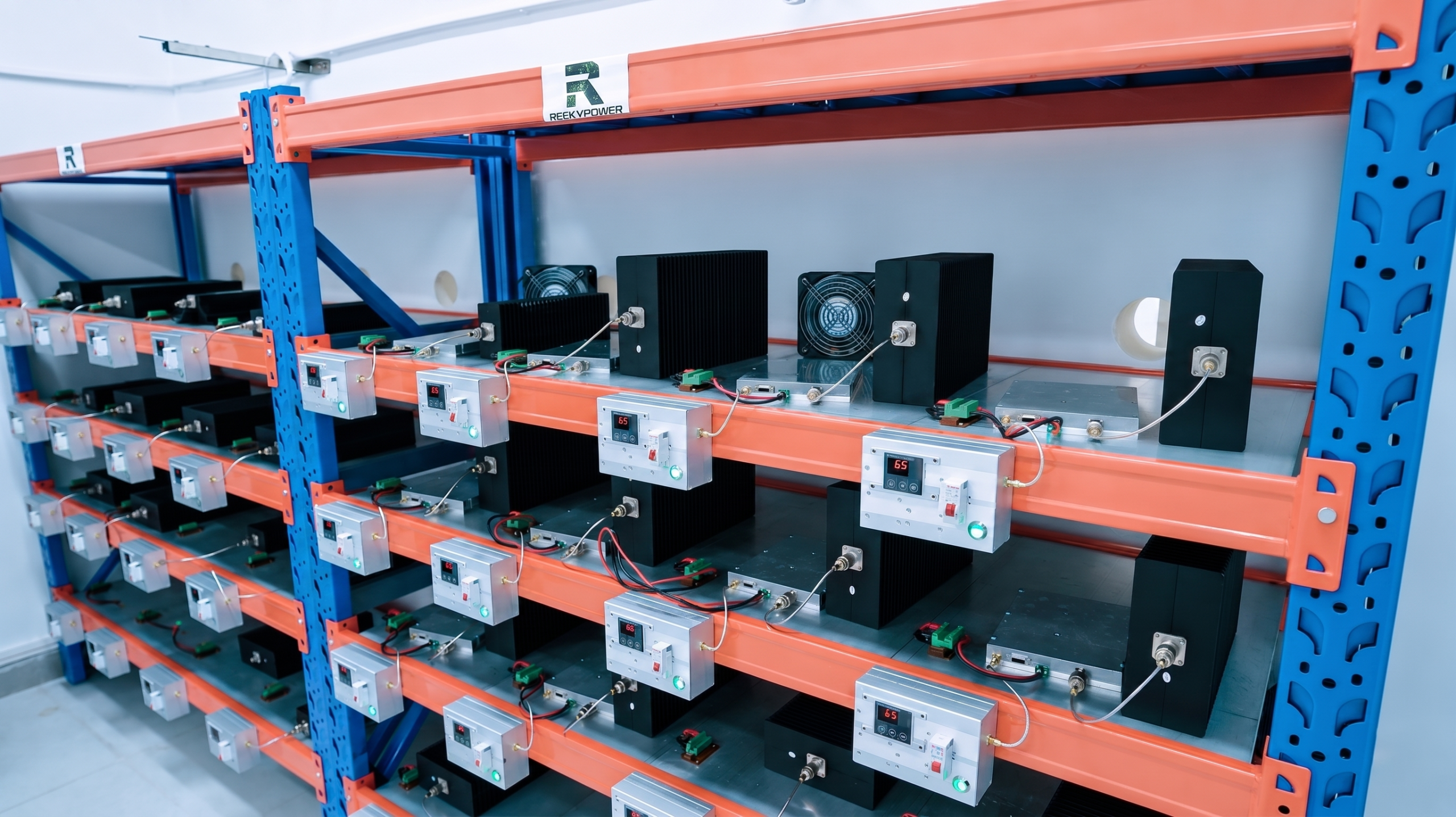
RF PA batch burn-in is often reduced to one line in a supplier report: “72 hours passed.” That statement may sound reassuring, but the hour count alone does not prove that the correct RF condition, DC boundary, load, cooling setup, monitoring points, or acceptance limits were used.
A useful burn-in record should show what happened to each production module before, during, and after the test. It should reveal abnormal output drift, current change, temperature rise, alarm events, protection behavior, and outlier units under a defined operating condition.
Before approving custom RF Power Amplifier modules, buyers should define the burn-in object, test coverage, RF state, 28 V supply boundary, load condition, cooling method, monitoring interval, stop conditions, drift limits, repair rules, and required S/N-linked report.
1. What RF PA Burn-In Can—and Cannot—Prove
RF PA module burn-in is a production screening process. It operates completed boards or modules under a defined electrical and thermal condition to expose early-life weakness that may not appear during a short functional test.
Burn-in can help identify:
- Abnormal output drift
- Unexpected current change
- Excessive temperature rise
- Intermittent control behavior
- Alarm or protection events
- Unstable thermal contact
- Assembly-related weakness
- Units that behave differently from the rest of the batch
A short bench test may confirm that a module turns on and reaches the expected output at one moment. Burn-in adds time and operating stress, allowing gradual or intermittent problems to become visible.
However, burn-in has clear limits.
It does not by itself prove:
- Complete field lifetime
- Reliability under every environment
- Performance across the full frequency band
- Ruggedness under uncontrolled mismatch
- That the approved BOM was actually used
- That one specific GaN device caused a failure
- That all future batches will behave the same way
Evidence Boundary: Burn-in can expose a weak RF PA module under a defined stress condition, but it cannot identify the GaN device or any other single component as the root cause without traceable failure analysis.
A module-level abnormality may originate from:
- GaN device variation
- Bias circuitry
- Matching networks
- PCB grounding
- Thermal interface quality
- DC input path
- Connector condition
- Assembly variation
- Cooling condition
- Test fixture or calibration error
For that reason, a failed burn-in result should trigger isolation and evidence review rather than an immediate assumption that one component is defective.
The page should also distinguish three different test levels.
Device-level burn-in
This applies to individual semiconductor devices or ICs before they become part of a finished RF PA assembly.
Board- or module-level burn-in
This applies to a completed RF PA board or enclosed module. It is the main subject of this article.
System run-in
This applies to a complete cabinet, rack, multi-channel assembly, power distribution system, or integrated controller.
These three test levels do not use the same conditions or prove the same things. A semiconductor screening condition should not be copied directly into a finished RF PA module test without engineering justification.
2. What Burn-In Boundary Must Be Defined Before Testing
The first question should not be only:
How many hours was the module burned in?
The stronger question is:
Which modules were tested, under what RF, DC, load, cooling, and monitoring conditions, and against which acceptance limits?
A complete burn-in plan should define the following boundaries.
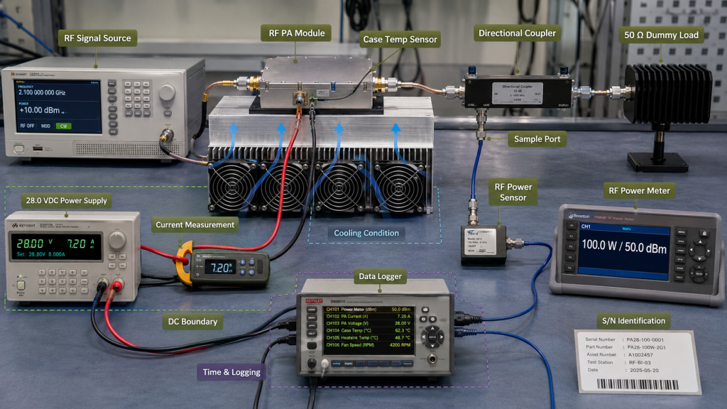
Device under test
State whether the test covers:
- Bare RF PA board
- Enclosed RF PA module
- Module with external heatsink
- Module installed in a cabinet
- Complete multi-channel system
Coverage
State whether the plan uses:
- 100% production screening
- Lot sampling
- First-article screening
- Repaired-unit requalification
- Process-change verification
“100% burn-in” is not a complete answer unless the tested object and conditions are also defined.
RF condition
Define:
- Frequency point or frequency sequence
- RF input drive
- Target RF output
- CW, high-duty, pulsed, or another duty cycle
- Continuous or staged operation
- Output enabled time
- Any planned command cycling
Burn-in may use a representative frequency, target project frequency, or approved sequence. It does not automatically need to operate at every frequency point throughout the entire duration.
It also does not replace a separate RF output after burn-in recheck or swept-frequency full-power verification.
DC condition
Record:
- Supply voltage
- Current range
- Current limit
- Cable and connector boundary
- Voltage measured at the supply or module input
- Start-up and steady-state current behavior
For a 28 V RF PA system, the test should state where the voltage is measured and whether cable drop is included.
Load condition
Define:
- 50 Ω dummy-load boundary
- Directional coupler or monitoring path
- FWD and REV measurement method
- Allowed VSWR
- Cable-loss correction
- Load power rating
- Cooling for the load
Normal burn-in should use a stable, controlled RF load.
FWD, REV, and VSWR may be monitored to confirm that the test path remains stable. That does not mean ordinary burn-in proves mismatch ruggedness. Controlled mismatch testing should remain a separate qualification activity.
Cooling condition
State:
- Heatsink configuration
- Fan or airflow condition
- Thermal-interface state
- Baseplate, case, or ambient reference
- Temperature-sensor location
- Cabinet or open-bench setup
Do not describe measured case temperature as semiconductor junction temperature unless a supported thermal model or direct measurement method is available.
Time and logging
Define:
- Total duration
- Warm-up period
- Logging interval
- Data retention method
- Alarm timestamp
- Stop conditions
- Restart rule after interruption
RF SKYPOWER’s production screening can include 72-hour module burn-in, but the hour count should remain connected to the approved RF state, 28 V supply boundary, load, cooling condition, monitored trends, failure rule, and S/N-linked report.
3. What Must Be Monitored Before, During, and After Burn-In
A good report should show more than a final “Pass” label.
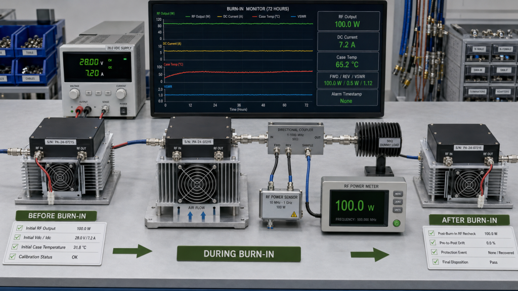
Before burn-in
Record the initial state of each module:
- Module S/N
- Model number
- Hardware revision
- PCB revision where applicable
- BOM or process revision
- Test-station identity
- Calibration status
- Test frequency
- RF input drive
- Initial output power
- Initial Vdc and Idc
- Initial case or baseplate temperature
- Initial alarm and protection status
The initial measurements create the baseline needed to judge later drift.
They should also connect to RF Power Amplifier incoming-part control and production traceability. Burn-in cannot prove that materials match the approved BOM if lot and production records are missing.
During burn-in
Monitor the parameters that can reveal instability:
- RF output trend
- DC current trend
- Voltage at the defined reference point
- Case or baseplate temperature
- FWD power
- REV power
- VSWR
- Alarm events
- Foldback or shutdown events
- Control response
- Restart or recovery behavior
- Time of each anomaly
A supplier should not report only the highest or final value. Trend data is useful because a module may remain inside a final limit while still showing abnormal movement during the test.
Examples include:
- Output falling gradually while current rises
- Temperature increasing without a corresponding change in output
- Repeated alarm events that recover automatically
- One module requiring more current than the rest of the batch
- Output returning after a restart without an explained root cause
After burn-in
Repeat the required checks under the same defined boundary:
- RF output
- Gain or output flatness where required
- Vdc and Idc
- Case or baseplate temperature
- Alarm status
- Protection recovery
- Control response
- Visual inspection where justified
- Final S/N disposition
A module should not pass only because it still powers on.
The final decision should compare the post-burn-in result with:
- The project acceptance limit
- The module’s pre-burn-in baseline
- The rest of the tested batch
- Any approved Golden Sample reference
RF PA Burn-In Evidence Map
| Stage | Evidence Required | Weak Record |
|---|---|---|
| Before | S/N, revision, test boundary, initial RF/DC/temperature | “Unit ready” |
| During | Output, current, temperature, alarms, protection events, time | “72 h passed” |
| After | RF recheck, drift, recovery, inspection, final disposition | “Still powers on” |
| Batch | Unit spread, outliers, failure count, clustered trends | One batch screenshot |
A strong report makes it possible to reconstruct what happened to each delivered module.
4. How to Judge Drift, Batch Spread, and Outliers
Burn-in acceptance should not rely on only one final value.
Four different comparisons are needed.
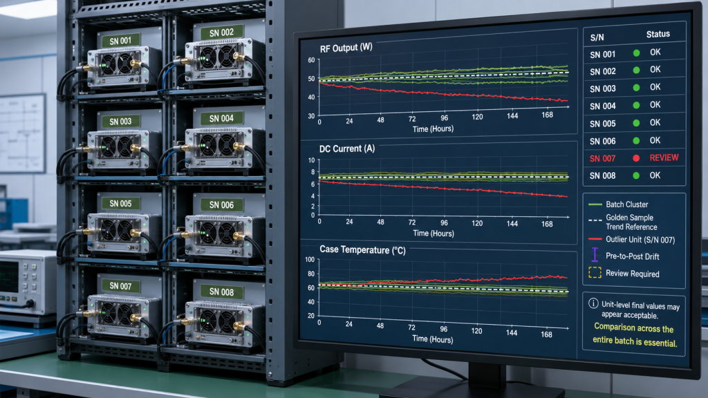
Individual acceptance limit
Each module must remain inside the agreed minimum and maximum limits for:
- RF output
- Current
- Temperature
- Alarm state
- Protection behavior
- Post-burn-in performance
Pre-to-post drift
Compare each module with its own baseline.
Possible drift items include:
- RF output change
- Current change
- Temperature change
- Gain change
- Alarm behavior
- Recovery behavior
A unit may remain inside the final limit yet still deserve Review when its pre-to-post drift is abnormal relative to the rest of the batch.
Batch spread
Compare the tested S/N units under the same boundary.
Questions include:
- Are most units clustered closely?
- Is one unit a clear outlier?
- Are multiple units drifting in the same direction?
- Does one production group show a wider spread?
- Do repaired units behave differently from unrepaired units?
Clustered shift
A single abnormal unit may be an isolated issue.
Several similar abnormalities may indicate:
- Material-lot variation
- Bias adjustment change
- Thermal-interface process variation
- Assembly change
- Test fixture problem
- Calibration problem
- Cooling inconsistency
- Process-control weakness
This is why a batch summary should not replace unit-level data.
Golden Sample and Locked BOM
A Golden Sample can support:
- Test setup verification
- Production comparison
- Trend review
- Investigation of abnormal units
But “close to the Golden Sample” is not a measurable acceptance limit.
The report still needs defined values for:
- Minimum output
- Maximum output
- Allowed current range
- Allowed temperature
- Allowed pre-to-post drift
- Alarm rule
- Protection-event rule
- Post-burn-in RF requirement
A Locked BOM also cannot be proven by burn-in alone.
BOM compliance requires:
- Material traceability
- Approved alternatives
- Production records
- Engineering change control
- Module S/N linkage
Burn-in supplies performance evidence. It does not replace production identity evidence.
Where the project depends on device-lot control or substitution review, the abnormal result should be connected to GaN device quality verification rather than automatically blaming the GaN die.
5. What Should Happen After a Failure, Repair, or Process Change
A failed burn-in unit should not move directly from “Fail” to “Repaired and Passed” without a controlled evidence chain.
Use the following sequence.
1. Record the event
Capture:
- S/N
- Time
- Operating state
- RF output
- Vdc and Idc
- Temperature
- Alarm or protection state
- Test-station condition
2. Quarantine the affected module
Prevent the module from returning to the shipment group before review.
3. Confirm the test setup
Check:
- Calibration
- RF cable and coupler
- Load
- Power supply
- Cooling
- Logging system
- Control commands
A fixture or cooling problem can make a good module appear weak.
4. Isolate the failure
Review possible causes across:
- RF device
- Bias circuit
- Matching network
- Thermal path
- DC path
- Connector
- PCB assembly
- Control interface
- Test setup
5. Review lot and process information
Connect the failed unit to:
- Component lots
- Hardware revision
- PCB revision
- Assembly date
- Process revision
- Rework history
- Related S/N units
6. Decide whether the issue is individual or batch-related
One isolated anomaly may remain a unit-level investigation.
Repeated or clustered failures should trigger:
- Batch Hold
- Lot review
- BOM review
- Process review
- Fixture review
- Calibration review
- Corrective action
7. Control repair or rework
The record should identify:
- Failure found
- Repair performed
- Parts changed
- Process used
- Approval authority
- Inspection result
8. Repeat full functional testing
Do not retest only the symptom that caused the failure.
Repeat the required RF, DC, thermal, control, alarm, and protection checks.
9. Repeat burn-in where required
A repaired module may need a complete new burn-in cycle when the repair affects the stressed path or when the project acceptance plan requires it.
10. Issue a new final report
The final report should replace or clearly supersede the previous failed record.
Repeated repairs without root-cause review are not evidence of a strong production process.
When several modules show similar drift, shutdown, current, or temperature behavior, hold the batch rather than repeatedly repairing individual modules and releasing them one by one.
6. What Evidence Should Approve, Review, or Hold Shipment?
Burn-in should end with a shipment decision, not only a test-duration statement.
Approve
Approval is reasonable when:
- The test boundary is fully defined.
- Required coverage is complete.
- Each module is linked to an S/N.
- Output, current, and temperature trends remain acceptable.
- No unexplained alarm or protection event remains.
- Pre-to-post drift is inside the agreed limit.
- The post-burn-in RF check passes.
- Repair and process records are complete.
- BOM and revision identity are traceable.
Review
Keep the unit or batch in Review when:
- One trend is unexplained.
- Drift is close to the limit.
- A protection event occurred but recovered.
- The test was interrupted.
- A repaired unit needs additional evidence.
- A process change has not been fully requalified.
- One module differs materially from the batch pattern.
- A final result passes, but the trend remains abnormal.
Review means engineering judgment is required before release.
Hold
Keep the unit or batch on Hold when:
- The burn-in boundary is missing.
- S/N-linked data is missing.
- Repeated abnormal drift occurs.
- Shutdown or foldback is unexplained.
- Multiple units show the same failure.
- Rework is uncontrolled.
- The post-burn-in RF check fails.
- BOM or process identity is unclear.
- The load or cooling condition was not controlled.
- The report shows only a duration and final Pass label.
Burn-In Shipment Decision Matrix
| Decision | Typical Condition | Required Action |
|---|---|---|
| Approve | Boundary, trends, retest and S/N evidence are complete | Release |
| Review | One drift, interruption, repair or change needs investigation | Engineering review |
| Hold | Repeated faults, failed retest or missing traceability remains | Stop shipment |
Burn-in should also be reviewed as one part of RF PA reliability testing before shipment. It does not replace swept-frequency output testing, protection validation, thermal verification, mismatch testing, or environmental evidence where those items apply.
The final S/N result should then become part of the project’s C-UAS RF PA acceptance checklist.
Conclusion
RF PA batch burn-in is useful only when its boundary and evidence are clear.
A strong record should show:
- Which module was tested
- Which RF, DC, load, and cooling conditions were used
- What was monitored
- How each value changed
- Which anomalies occurred
- What happened after repair
- Whether the final result supports Approve, Review, or Hold
A statement such as “72 h passed” cannot replace S/N-linked trend data, post-burn-in RF verification, failure handling, and batch-level review.
RF SKYPOWER can support early engineering review for RF PA batch burn-in. Send the frequency range, output target, duty cycle, 28 V supply boundary, load condition, cooling method, module quantity, burn-in duration, monitoring points, drift limits, repair rule, and required S/N-linked report format.
Contact RF SKYPOWER before a vague burn-in record hides abnormal drift, an unexplained protection event, or a batch-level process problem.