










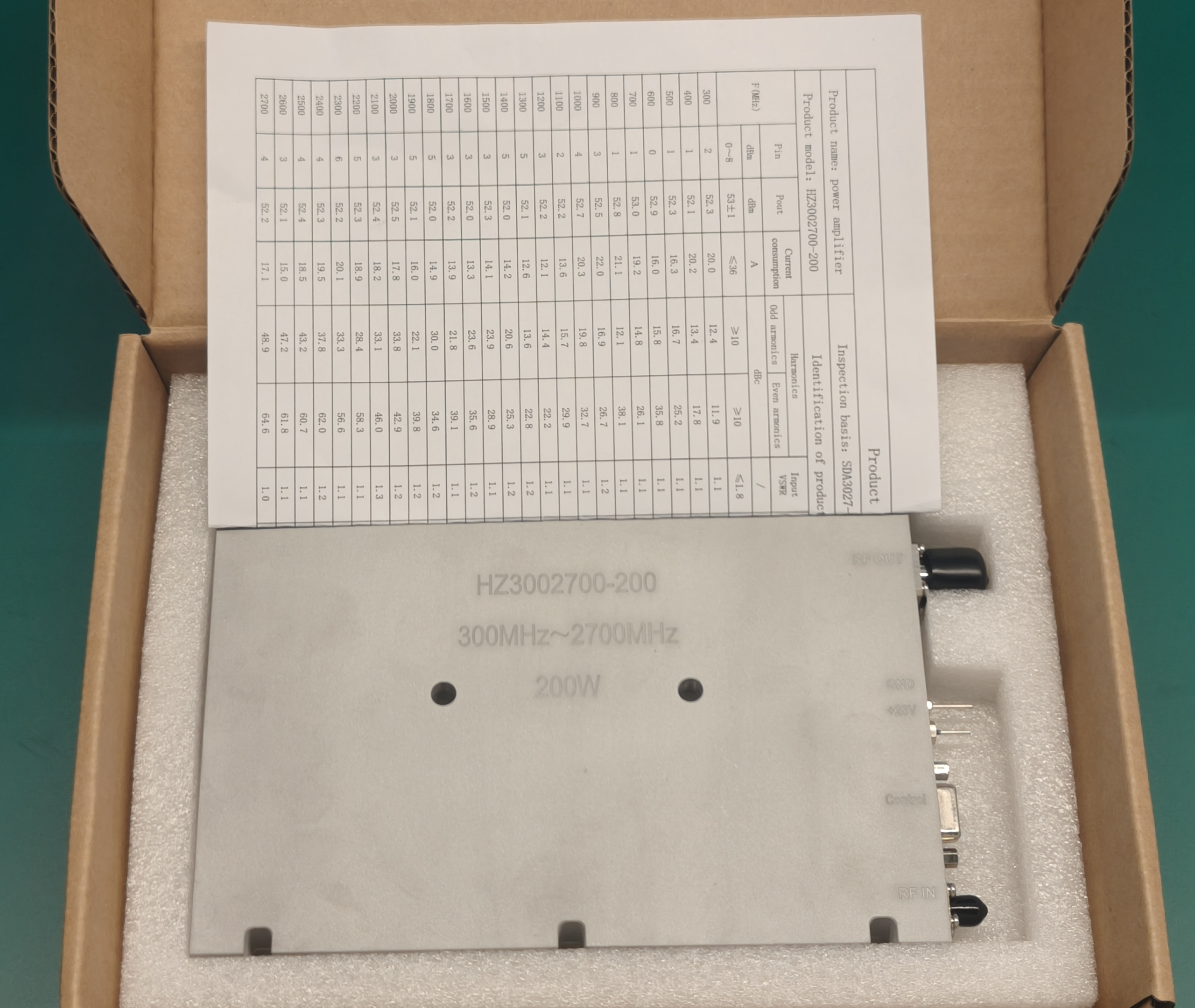
An RF PA test report should provide more than one output-power value.
It should connect the product model and individual product identification with the inspection basis, test condition, measured RF performance, operating limits, and final test result.
For buyers of custom RF Power Amplifier modules, this unit-level evidence helps confirm that the delivered module was tested across its required operating band instead of being approved only from a catalog specification or representative sample.
1. What Should an RF PA Test Report Identify?
Before reviewing individual measurements, the buyer should first confirm what was tested.
A useful report should identify:
- Product name
- Product model
- Individual product identification
- Inspection basis
- Test temperature
- Final test result
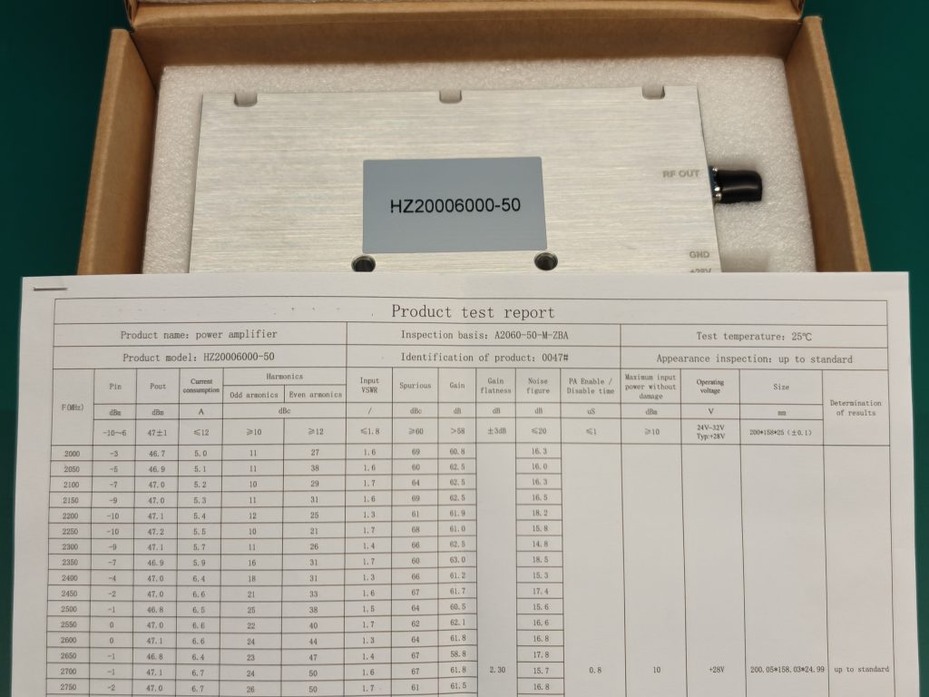
Product model
The model number identifies the RF PA type covered by the report.
It allows the buyer to compare the report with the ordered:
- Frequency range
- Rated output power
- Operating voltage
- Mechanical format
- Application requirement
The model shown in the report should match the module being delivered.
Individual product identification
The individual product identification connects the measurements to one specific module.
Modules with the same model number may show small differences in:
- Output power
- Gain
- Current consumption
- Input VSWR
- Harmonics
- Gain flatness
When each module has its own identification and corresponding test report, the buyer can review the measured performance of the actual delivered unit.
Inspection basis
The inspection basis identifies the stated requirement used to evaluate the module.
It gives context to the measured data and final result. Without this reference, the buyer may see test values but cannot easily connect them to the applicable acceptance boundary.
Test temperature
RF PA performance can change with thermal conditions.
Recording the test temperature defines the environment in which the reported measurements were obtained and helps keep comparisons between units consistent.
Final test result
The final result indicates whether the module met the stated inspection basis under the recorded test condition.
It should apply to the complete set of measured electrical, RF, operating, and mechanical results included in the report.
2. Which RF Performance Results Should Be Recorded?
A useful RF PA test report should show performance across the required operating band rather than relying on one center-frequency value.
RF input and output power
RF input power, often shown as Pin, defines the drive condition applied to the amplifier.
RF output power, often shown as Pout, records the resulting RF power at each test frequency.
These two values should be read together. An output-power result is difficult to interpret without knowing the input condition used to produce it.
Results across the operating band help the buyer review:
- Band coverage
- Output consistency
- Band-edge performance
- Frequency-to-frequency variation
Current consumption
Current consumption records the DC demand of the module under the tested RF condition.
It supports:
- Power-supply sizing
- DC cable selection
- Connector-current planning
- Thermal design
- System power budgeting
Output power and current should be reviewed together against the stated inspection basis.
Input VSWR
Input VSWR records the RF input match under the tested condition.
It helps the integrator evaluate how the amplifier interacts with the upstream signal source and RF cable path.
Testing VSWR across the operating band provides more useful evidence than one center-frequency value.
Harmonics and spurious results
Harmonic results show unwanted energy at multiples of the intended signal frequency.
Spurious results record other unintended signals outside the main carrier.
These values support:
- Filter planning
- RF chain design
- EMC review
- System integration
- Acceptance against the stated inspection basis
A module may reach its expected output power while still requiring spectral performance to be reviewed separately.
Gain and gain flatness
Gain connects the applied RF input with the measured RF output.
Gain flatness shows how much that gain changes across the operating band.
For wideband RF PA modules, gain flatness helps the integrator estimate how much drive adjustment may be required between different operating frequencies.
Noise figure
Where included, noise-figure data provides an additional RF reference.
It is not normally the primary acceptance value for an RF power amplifier, but it can support broader technical comparison of the tested RF path.
RF Performance Review Table
| Report Item | What It Shows | Why It Matters |
|---|---|---|
| Frequency | Tested operating point | Confirms band coverage |
| Pin | Applied RF drive | Defines the input condition |
| Pout | Measured RF output | Confirms power performance |
| Current | DC demand | Supports power and thermal design |
| Input VSWR | Input match | Supports RF source integration |
| Harmonics | Harmonic emissions | Supports filtering and EMC review |
| Spurious | Unwanted signals | Supports spectral acceptance |
| Gain | Amplification level | Connects input and output |
| Gain flatness | Variation across frequency | Shows wideband consistency |
| Noise figure | Additional RF reference | Supports technical comparison |
These results provide a more complete picture when reviewed together rather than as isolated headline values.
3. Why Does Unit-Level Reporting Matter?
A model specification describes what a product type is designed to achieve.
A unit-level test report shows what one specific delivered module achieved during testing.
This distinction matters in batch delivery.
Modules may share the same:
- Model
- Frequency range
- Rated output power
- Mechanical structure
- Operating-voltage range
Their measured values may still vary slightly.
When every module has an individual product identification and corresponding test results, the buyer can match the delivered unit to its actual evidence.
This is more useful than receiving one representative report for an entire batch.
What unit-level evidence allows the buyer to confirm
The buyer can verify that:
- The report belongs to the delivered module.
- The module was tested under the stated inspection basis.
- The required operating band was evaluated.
- Actual RF output and current were recorded.
- The final result applies to that specific unit.
Unit-level reporting can also support later comparison during integration, service, or retesting.
4. How Should Buyers Read Full-Band Test Results?
A wideband RF PA should not be judged from one center-frequency result.
The report should be reviewed across the required operating range.
Check output across frequency
Review whether Pout remains within the stated acceptance range at:
- Lower frequencies
- Mid-band frequencies
- Upper frequencies
- Required operational channels
This helps reveal frequency-dependent variation that one center-frequency value cannot show.
Compare Pin, gain, and Pout
Pin, gain, and Pout should be read together.
A change in output may be associated with:
- A different input drive level
- Frequency-dependent gain
- Band-edge response
- The recorded test condition
Reading the three values together gives the buyer a clearer view of amplifier behavior.
Compare current with output
Current should be compared with RF output against the stated inspection basis.
The purpose is not to expect identical current at every frequency. It is to confirm that DC demand remains consistent with the recorded RF operating condition.
Review flatness and spectral results
Gain flatness helps show how consistently the amplifier behaves across the band.
Input VSWR, harmonics, and spurious results provide additional evidence that output power is not the only acceptance concern.
These measurements can also support the evidence chain used in full-power RF PA testing.
5. What Other Results Support Shipment Acceptance?
An RF PA test report may also include operating and mechanical results that help the integrator confirm system compatibility.
Enable and disable time
Enable and disable time records how quickly the module responds to its control state.
The measured timing helps the integrator review whether the module response matches the required control sequence.
Maximum input power without damage
This value defines the upper RF input boundary used to prevent excessive drive during integration and operation.
Normal system input should remain below the stated limit.
Operating-voltage range
The stated DC operating range and typical voltage help the integrator confirm compatibility with the system power architecture.
This supports decisions involving:
- DC supply selection
- Voltage tolerance
- Cable voltage drop
- Protection settings
- Power distribution
A stated range such as 24–32 V, typ. +28 V gives the integrator a clear supply boundary.
Physical dimensions
Measured dimensions help confirm whether the module fits the required mechanical envelope.
This supports:
- Heatsink layout
- Mounting design
- Cabinet space
- Connector clearance
- Airflow planning
Test temperature
The recorded temperature provides context for all reported RF and electrical results.
It does not replace hot-state or environmental validation, but it defines the condition under which the values in the report were obtained.
6. What Should Be Confirmed Before Shipment?
Before shipment, the buyer should confirm that the report forms a complete and consistent record for the delivered module.
Product identity
Confirm that:
- The model matches the order.
- The individual identification matches the delivered unit.
- The report clearly belongs to that module.
Inspection condition
Confirm that:
- The inspection basis is stated.
- The test temperature is recorded.
- The operating-voltage condition is shown.
- Relevant operating limits are included.
Measured performance
Confirm that the required results are present across the operating band, including:
- Pin and Pout
- Current
- Input VSWR
- Harmonics
- Spurious results
- Gain and gain flatness
- Noise figure where included
Operating and mechanical evidence
Confirm that applicable values such as the following are recorded:
- Enable and disable time
- Maximum input power without damage
- Operating-voltage range
- Physical dimensions
Final result
Confirm that the report gives a clear final result based on the stated inspection basis.
A useful report should allow the buyer to answer four questions:
- Which module was tested?
- Under what inspection condition?
- Which electrical and RF results were measured?
- Did the unit meet the stated requirement?
These checks can also form part of a broader C-UAS RF PA acceptance checklist.
Conclusion
An RF PA test report should connect one delivered module with its actual measured performance.
The most useful report clearly links:
- Product model
- Individual product identification
- Inspection basis
- Test condition
- Full-band RF results
- Operating limits
- Final test result
Unit-level reporting helps buyers evaluate the actual module they will receive rather than relying only on a catalog specification or representative sample.
RF SKYPOWER can support early review of RF PA test and acceptance requirements. Send the target frequency range, output power, operating voltage, RF input condition, required test points, electrical limits, mechanical constraints, and shipment quantity.
Contact RF SKYPOWER to review the required unit-level RF PA test evidence before production and shipment.