










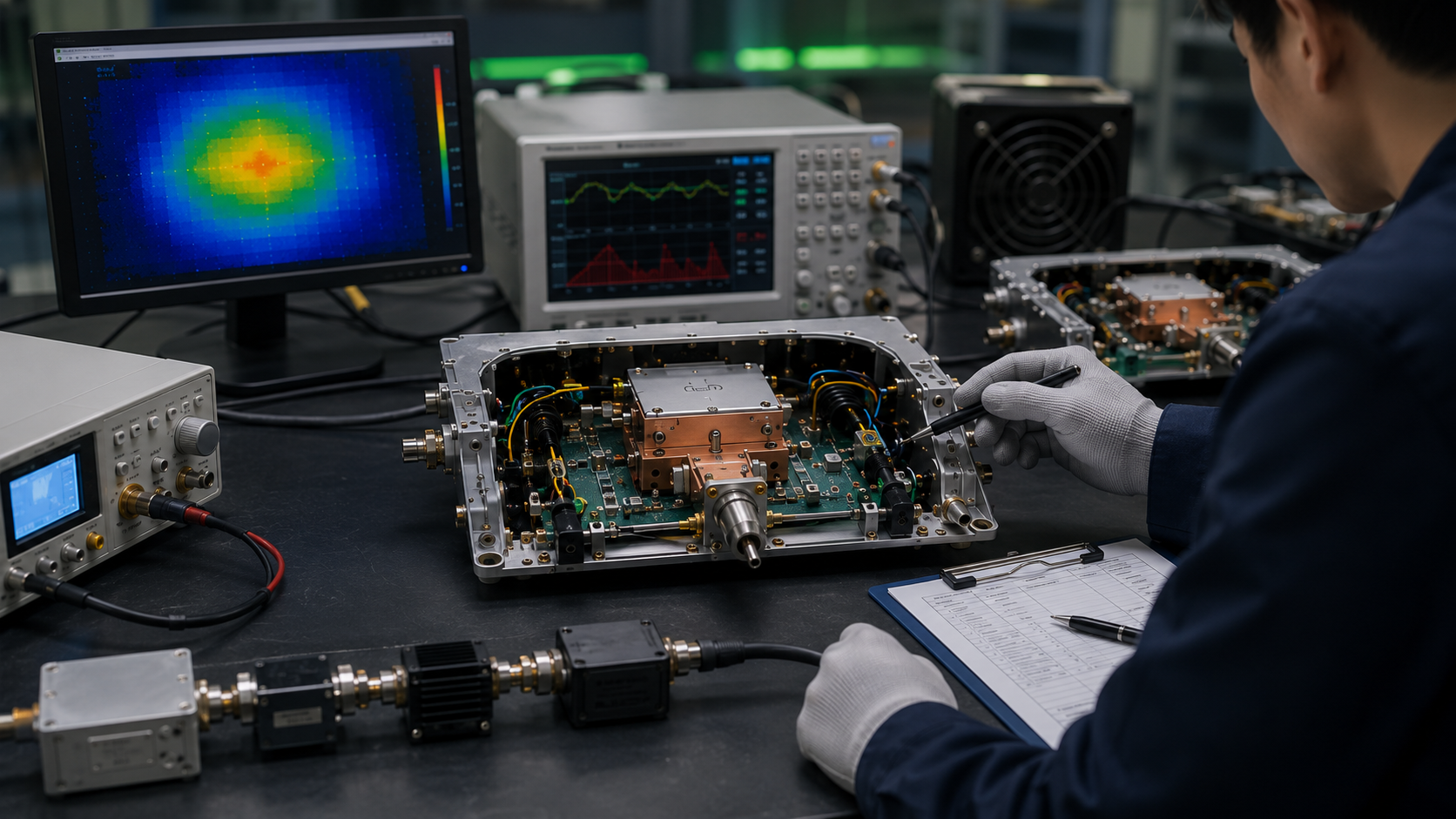
RF PA process changes can alter batch performance even when the BOM, model number, and schematic remain unchanged. Changes in thermal-interface application, assembly torque, shielding contact, grounding pressure, harness routing, connector fixation, cleaning, or test setup can affect hot-state output, current, temperature, protection behavior, and control feedback.
For buyers and system integrators, the issue is not whether every factory adjustment requires full retesting. The real issue is whether the affected engineering path was identified, the risk was classified, and the validation scope matched the possible failure mode.
A controlled review should connect six elements:
What changed → Which path is affected → Risk level → Required validation → Affected S/N → Updated release evidence
1. Why the Same BOM Can Still Produce Different RF PA Behavior
A BOM identifies the approved components used in an RF power amplifier module. It does not fully define how those components are assembled, contacted, cooled, routed, cleaned, fixed, or tested.
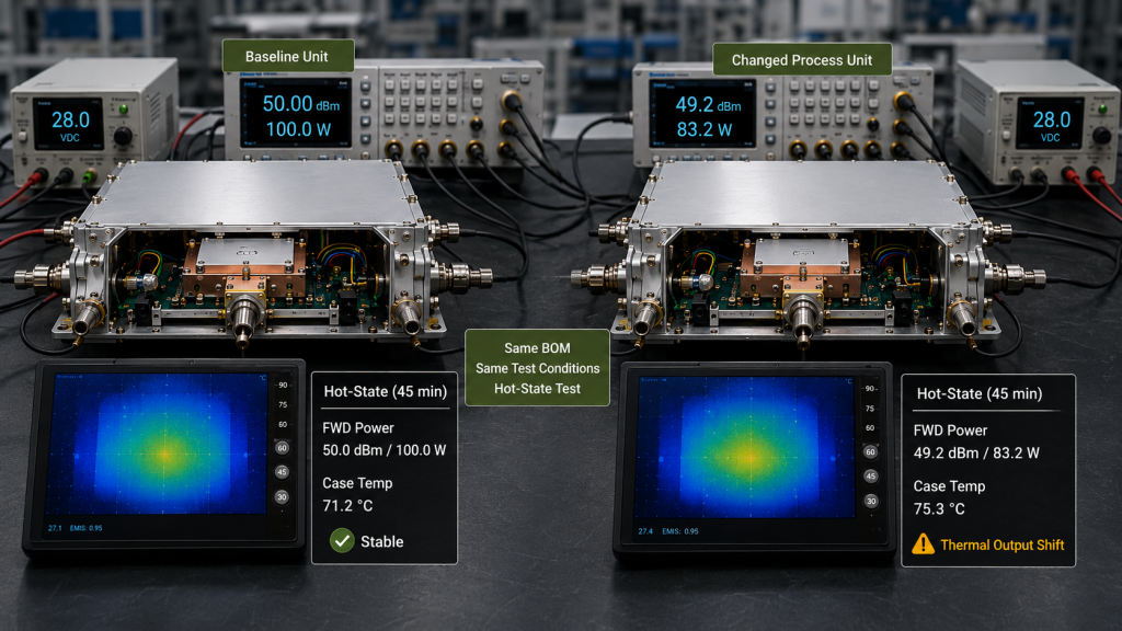
Two modules can use the same PCB, transistor, capacitors, connectors, enclosure, and control components while behaving differently after thermal soak or continuous RF operation.
Possible causes include:
- Uneven thermal-interface coverage
- Different mounting pressure beneath the final-stage device
- Changed screw torque or tightening sequence
- Reduced shielding or grounding contact
- Modified harness routing
- Connector movement during assembly
- Residue remaining after cleaning
- A changed test cable, attenuator, fixture, or correction value
These differences may not cause an immediate failure. Instead, they may appear as gradual output reduction, higher current, delayed temperature rise, unstable feedback, intermittent protection foldback, or increased variation between units.
A short room-temperature test may therefore show an acceptable result while a longer hot-state test reveals a weaker thermal contact, unstable connector, or inconsistent assembly condition.
Process Changes Are Not the Same as Every Production Change
The primary change type should be identified before the validation scope is selected.
- A BOM change alters what is built.
- A hardware-version change alters the defined engineering configuration.
- A supplier change alters the approved source or material lot.
- A process change alters how the approved design is assembled, contacted, routed, cooled, cleaned, or tested.
- A test-condition change alters how performance is measured or compared.
One event can involve more than one category. A new thermal-interface material, for example, may require both a supplier review and a process revision. The record should still identify the primary change and the engineering path it affects.
2. How to Classify RF PA Process Changes by Risk
Process-change risk should be based on the affected path, not on how small the adjustment looks.
A minor visual change can be low risk. A small change beneath the power transistor can be high risk because it affects heat transfer during continuous operation.
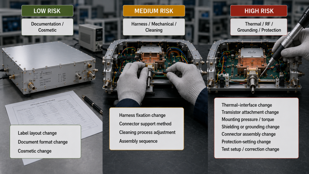
Low-Risk Changes
A low-risk change does not affect the RF, thermal, grounding, control, mechanical, supply, or measurement path.
Typical examples include:
- Label-layout changes
- Document-format changes
- Internal instruction numbering
- Non-technical packaging text
- Cosmetic changes outside functional interfaces
These changes normally require a documented review rather than RF performance testing.
Medium-Risk Changes
A medium-risk change affects mechanical fixation, harness routing, connector handling, cleaning, or local assembly conditions without directly changing the main RF or thermal path.
Examples include:
- A revised harness fixation point
- A changed connector-support method
- A modified enclosure assembly sequence
- A cleaning-process adjustment
- A different local mechanical inspection step
The risk increases when the change can influence voltage drop, connector stress, control feedback, or vibration behavior.
High-Risk Changes
A high-risk change affects a path that can directly alter RF output, heat transfer, grounding, protection behavior, or measurement comparability.
Examples include:
- Thermal-interface material or application changes
- Transistor attachment changes
- Mounting-pressure or torque changes
- Shielding-contact changes
- Grounding-contact changes
- RF connector assembly changes
- Protection-setting changes
- Test-fixture, cable, attenuator, or correction-method changes
Before approval, the review should answer:
- Which engineering path changed?
- Which performance indicators could be affected?
- Which approved baseline will be used?
- Which S/N units are covered by the change?
Descriptions such as “minor improvement” or “no schematic change” are not sufficient when the affected path and validation boundary remain undefined.
3. Which Engineering Paths Can Affect Batch Performance
Different paths produce different symptoms. The validation plan should follow the affected path rather than repeat the same generic test after every change.
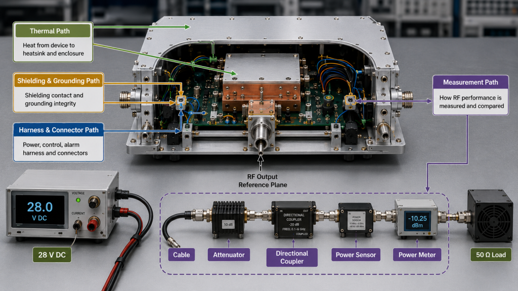
Thermal Path
The thermal path includes transistor attachment, thermal-interface material, mounting pressure, spreader contact, enclosure contact, heatsink mounting, and airflow conditions.
A change can affect:
- Hot-state output and current
- Temperature rise and stabilization time
- Protection foldback behavior
- Unit-to-unit thermal variation
Thermal-path changes should be checked after sufficient operating time for output, current, and temperature to stabilize.
Detailed RF PA thermal-interface process control becomes especially important when interface thickness, surface flatness, material coverage, or mounting pressure can create local heat-transfer differences.
Shielding and Grounding Path
Shielding and grounding changes can influence RF stability, unwanted coupling, alarm feedback, and enclosure-dependent behavior.
Important symptoms include:
- Frequency-dependent output variation
- Feedback changes after final enclosure assembly
- Increased sensitivity to cabinet grounding
- Intermittent behavior linked to contact pressure
These changes should be reviewed under the final mechanical condition, not only with the module open on a bench.
Harness and Connector Path
Harness routing and connector fixation can influence DC delivery, control communication, feedback signals, and mechanical reliability.
Possible results include:
- Voltage drop under load
- Intermittent control feedback
- Connector stress
- Cable movement during vibration
For remote or multi-band integration, RF PA control-interface reliability should be checked under realistic startup, operating, and protection conditions.
Measurement Path
A changed cable, attenuator, directional coupler, fixture, power sensor, correction value, or reference plane can create an apparent performance difference even when the RF PA module has not changed.
The review should confirm:
- RF output reference plane
- Cable and connector correction
- Attenuator value
- Sensor range and calibration status
- Input-drive condition
- DC supply condition
- Cooling condition
- Operating time before data capture
When the measurement path changes, old and new data should not be compared until the two setups have been correlated.
4. How Retesting Should Match the Changed Process
The validation scope should be proportional to the affected path and the possible customer risk.
Repeating every test after every administrative change is inefficient. Performing only a center-frequency output check after a thermal, grounding, or measurement change is not enough.
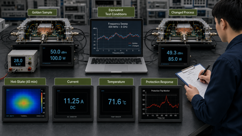
The comparison should use an approved reference condition, such as:
- A Golden Sample
- An approved hardware version
- A controlled production baseline
- A previously accepted S/N-linked report
Old and new conditions should remain equivalent in:
- Frequency range
- Input drive
- DC voltage
- Cooling method
- Load condition
- RF reference plane
- Correction method
- Operating duration
Process Change Risk and Retest Matrix
| Process Change | Affected Path | Risk Level | Recommended Validation | Required Record |
|---|---|---|---|---|
| Label or document format | None | Low | Document review | Change note |
| Cleaning-process adjustment | Surface / mechanical | Medium | Visual inspection and targeted functional check | Process revision and inspection record |
| Harness routing or fixation | Control / DC / mechanical | Medium–High | Voltage, feedback, connector, and vibration-related checks | Harness revision and affected-unit range |
| Thermal-interface method | Thermal | High | Hot-state output, current, temperature, and protection review | Baseline comparison and affected S/N |
| Shielding or grounding contact | RF / grounding | High | RF stability, feedback, and enclosure-contact review | Validation record and affected batch |
| RF connector assembly | RF / mechanical | High | Swept output, connector inspection, and repeatability check | Assembly revision and retest results |
| Test cable, fixture, or attenuator | Measurement | High | Old/new setup correlation and data-comparability review | Test-setup revision and report update |
When Expanded RF Validation Should Be Triggered
Expanded RF validation should be triggered when a change can affect:
- Output across frequency
- Gain flatness
- Hot-state performance
- Current consumption
- Reflected-power behavior
- Protection response
- Alarm feedback
- Measurement comparability
The exact scope should follow the affected path and the approved acceptance boundary.
For a high-risk change, a single center-frequency screenshot does not provide enough evidence. Validation should include full-power swept testing across the frequency range and operating conditions relevant to the approved module configuration.
When Thermal Soak or Burn-In Adds Value
Thermal soak or burn-in is useful when a process change can create delayed rather than immediate symptoms.
Examples include:
- Thermal-interface changes
- Mounting-pressure changes
- Grounding-contact changes
- Harness or connector fixation changes
- Cleaning changes that may leave residue
The purpose is not only to prove that the module remains powered. The test should show whether output, current, temperature, feedback, or protection behavior changes after heat and operating time accumulate.
When a Targeted Check Is Sufficient
A targeted check may be sufficient when:
- The affected path is clearly limited.
- The possible failure mode is understood.
- The approved baseline remains valid.
- The selected check directly verifies the identified risk.
- RF and thermal data comparability remain unchanged.
The validation record should state why the limited scope was selected.
5. What Process-Change Records Must Link to Each S/N
A successful retest has limited value when the factory cannot identify which units were built before and after the changed process.
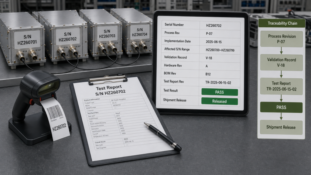
Each approved process change should identify:
- Process revision
- Implementation date
- Affected engineering path
- Assigned risk level
- Validation method
- Comparison baseline
- Affected S/N range
- Applicable hardware and BOM versions
- Updated inspection or test instruction
- Final approval status
The record does not need to disclose proprietary factory instructions. It should allow the buyer to determine which units were built under the changed condition and what evidence supports their release.
This is especially important when production spans multiple batches. Without an implementation date and affected S/N range, the validation result cannot be reliably connected to the delivered modules.
Process control should work together with version-controlled RF PA test reports. The process revision identifies how the unit was built. The report revision identifies how it was verified.
The final release evidence should show:
- Whether the unit was built before or after the change
- Which process revision applies
- Which validation record applies
- Whether the approved test method was used
- Whether the result is linked to the unit S/N
These records should also remain consistent with the S/N-linked test and acceptance evidence used for incoming inspection and shipment approval.
6. Frequently Asked Questions
Does Every Process Change Require a New Hardware Version?
No. A process revision can remain separate from the hardware version when the electrical design and approved components remain unchanged.
However, the changed process, implementation date, validation evidence, and affected S/N range should still be traceable. A new hardware version may be appropriate when the process change also alters the defined mechanical, electrical, thermal, or control configuration.
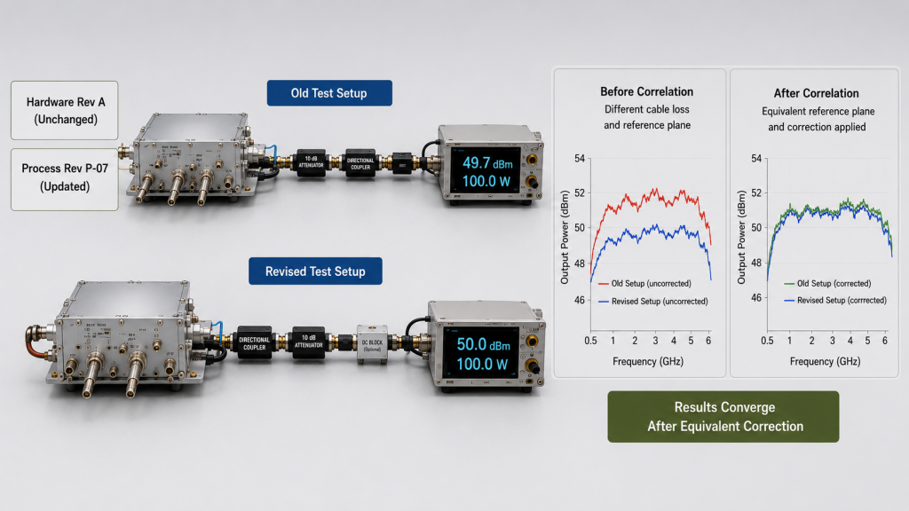
Can a Test-Fixture Change Create a False Performance Difference?
Yes. Changes in cables, attenuators, sensors, correction values, fixtures, or reference planes can make old and new results appear different even when the RF PA module has not changed.
The old and new measurement paths should be correlated before the revised setup is used for batch comparison or shipment approval.
RFQ: What Buyers Should Require Before Process-Change Approval
Before approving units produced under a changed process, buyers and system integrators should ask:
- What process changed?
- Which engineering path is affected?
- What risk level was assigned?
- What validation was performed against the approved baseline?
- Which S/N units are affected?
- Which shipment or test records were updated?
A weak answer describes the change as minor without defining its technical boundary.
A useful answer identifies the affected path, possible failure mode, validation method, comparison baseline, affected S/N range, and release evidence.
Conclusion
An unchanged BOM does not prove that an RF PA batch was built and verified under an unchanged process.
Thermal contact, shielding, grounding, harness routing, connector fixation, cleaning, and measurement conditions can all influence output, current, temperature, protection behavior, and batch repeatability.
A controlled process-change review should connect:
What changed → Which path is affected → Risk level → Required validation → Affected S/N → Updated release evidence
For projects requiring controlled batch delivery of custom RF power amplifier modules, RF SKYPOWER can support early engineering review of process-change risk and validation scope.
Please submit the frequency range, target output, duty cycle, cooling method, DC supply, control interface, affected process, validation requirements, S/N traceability format, shipment-report requirements, and deployment condition. RF SKYPOWER can then align the module configuration, verification boundary, and delivery evidence before batch approval.