


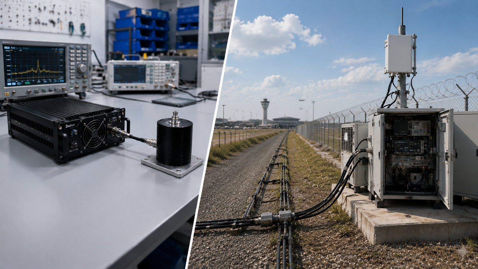
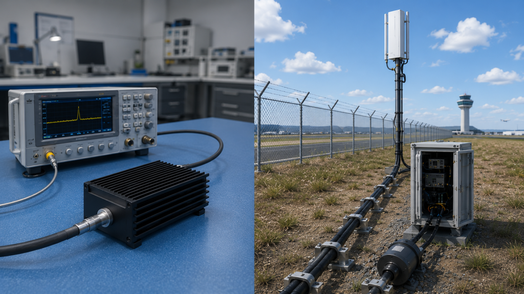
To check RF Power Amplifier Load before integration, start by comparing controlled 50Ω bench behavior with the real antenna path the module will see in the system. A clean dummy-load number can prove controlled module behavior, but it cannot prove what happens after the amplifier is connected to real antennas, feeder cables, connectors, waterproof joints, lightning protection, cabinet routing, thermal limits, DC supply behavior, and controller decisions.
This is the real customer choice behind the topic: should you approve the PA module because it reaches 100W or 200W on a bench load, or should you verify whether that output remains stable after the antenna path is connected? The conflict is simple: rated PA output describes module capability, but real antenna load decides whether that capability remains usable in the deployed system. In low-altitude security and C-UAS system integration, RF modules, antennas, feeder paths, cooling, supply, and controller feedback should be reviewed as one working chain, not as separate purchasing items.
For system integrators, RF engineers, and procurement reviewers, the safer decision is not to reject bench testing. The safer decision is to use bench testing as the starting point, then check how the RF Power Amplifier behaves with the real load path before final approval.
1. How to Verify RF Power Amplifier Antenna Load Stability
A 50Ω bench load does not prove field load stability because the load seen by the RF Power Amplifier changes once the module is connected to a real antenna path. A dummy load gives a stable, repeatable, controlled reference, which is why it remains essential for factory testing. The practical risk is clear: a module can pass output, current, temperature, and protection checks on the bench, then behave differently after the antenna, feeder cable, connectors, and installation environment are added.
For RF Power Amplifier modules for C-UAS integration, the bench result should answer “Can the module work under controlled conditions?” It should not be treated as the final answer to “Will the complete RF chain remain stable in the field?”
What does the bench load prove?
A 50Ω load helps engineers isolate the PA module from outside variables. It is useful for repeatable comparison, production QC, sample approval, and factory acceptance.
It usually helps confirm:
- Output power at the module port
- Gain and current behavior
- Basic thermal response
- Initial VSWR protection behavior
- Repeatability across units
What does the real antenna load reveal?
A real antenna load reveals how the full RF path behaves after the module leaves the lab. Here’s the engineering point: the PA sees the load created by everything connected after its output port, not only the antenna name on the datasheet.
Key Takeaway: Bench testing proves controlled module capability, while antenna-load coordination proves whether that capability survives the real RF path.
| Wrong Assumption | Better Check | Why It Matters |
|---|---|---|
| 50Ω pass means field pass | Test with real load path | Finds mismatch risk |
| PA port power equals antenna power | Define reference point | Avoids false expectations |
| Antenna is separate | Review PA + antenna together | Reduces late alarms |
| Protection will handle everything | Check trigger behavior | Prevents blind shutdowns |
This table helps buyers separate module proof from system proof before approving a design.
2. When Can Independent RF Power Amplifier Design Still Work?
Independent RF Power Amplifier design can still work when the load condition is fixed, verified, low-risk, and close to bench conditions. Not every project needs deep PA + antenna + full RF chain coordination. If the application is a lab platform, a narrowband prototype, or a fixed-load evaluation, the PA can often be selected and tested with limited system review.
That said, “independent” should never mean “load undefined.” This is where system integrators should pay attention: even a simple project needs a clear load boundary before the test result can be interpreted.
Which projects are lower risk?
Independent verification may be reasonable when the system has few unknowns. The key is not project size, but load stability.
Lower-risk conditions include:
- Fixed 50Ω load operation
- Short feeder path
- Narrow frequency range
- Known antenna already validated
- Low duty cycle
- Easy access for retesting
- Limited remote alarm requirements
What still needs to be defined?
Even in simple projects, the supplier and buyer should agree on test conditions. If those conditions are unclear, the same PA can look acceptable in one setup and weak in another.
Key Takeaway: Independent PA design is acceptable only when the load boundary is defined, stable, and close to the condition used during validation.
| Selection Condition | Independent PA Design Fit | Remaining Check |
|---|---|---|
| Lab dummy-load platform | High | Test reference point |
| Mature narrowband antenna | Medium | Antenna match data |
| Long outdoor feeder path | Low | Full path review |
| Multi-module C-UAS rack | Low | System coordination |
This table prevents over-engineering simple projects while still protecting higher-risk deployments.
3. When Does Antenna Load Become a Design Requirement?
Antenna load becomes a design requirement when it can change RF Power Amplifier output stability, reflected power, protection behavior, temperature, current, or controller decisions. At that point, the antenna is no longer a final-stage accessory. It becomes an input condition for PA selection, protection planning, and acceptance testing.
A C-UAS antenna system design should therefore be reviewed together with PA output target, feeder length, connector path, duty cycle, and alarm feedback. The better check is simple: if the real antenna path can change PA behavior, it belongs in the design discussion.

Which conditions trigger coordination?
You should bring antenna load into the PA design stage when the RF chain has field variables that cannot be simulated by a clean dummy-load test.
Typical triggers include:
- Wideband operation
- Long feeder cable
- Outdoor antenna location
- Waterproof joints or lightning protection
- Multiple adapters or splitters
- Vehicle vibration
- High duty cycle
- Remote monitoring requirement
Why should this happen before field testing?
Late antenna-load review turns engineering work into troubleshooting. If the PA supplier only sees the problem after installation, the team may spend days proving whether the issue is the module, antenna, feeder, connector, power supply, heat path, or controller logic.
Key Takeaway: Antenna load should enter the design phase as soon as real load behavior can affect output, reflected power, protection, heat, current, or control logic.
| Field Condition | Selection Risk | Better Starting Point |
|---|---|---|
| Long feeder cable | Lower antenna-end power | Define reference point |
| Wide frequency range | Uneven match by band | Check band-specific load |
| Vehicle platform | Moving connector stress | Review cable strain |
| Remote site | Slow fault diagnosis | Separate alarm causes |
This table shows why antenna load is a design input, not just an installation detail.
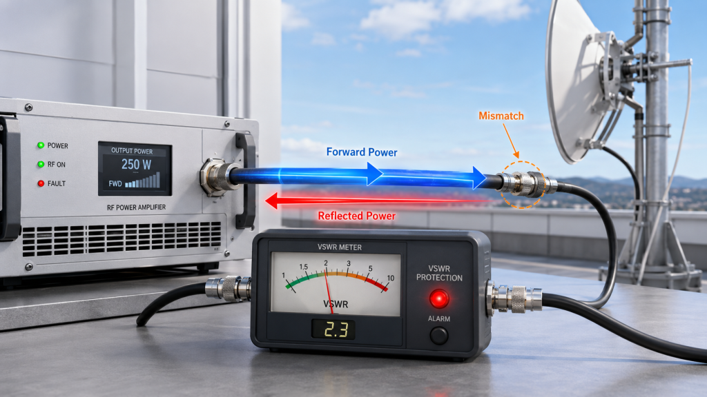
4. How RF Power Amplifier Load Affects Protection Behavior
Load mismatch changes output and protection because RF Power Amplifier behavior depends on the reflected power and impedance condition seen at the output. When matching is good, more RF energy reaches the intended antenna path. When matching is poor, part of that energy returns toward the PA output stage and may trigger reflected-power or VSWR protection.
This does not mean every mismatch destroys the module. The real issue is operational behavior: output may drop, alarms may appear, protection may reduce power, or the controller may see unstable status. When RF Power Amplifier VSWR protection appears in field logs, the full antenna load path should be reviewed before the PA module is blamed.
What changes inside the RF chain?
Mismatch changes the condition seen at the PA output. Here’s the field reality: the alarm may be reporting the condition of the chain, not a failed amplifier.
Common symptoms include:
- Reflected power rising
- Output becoming unstable
- VSWR alarm events
- Protection shutdown or derating
- Temperature increase
- Controller alarm fluctuation
- Band-specific weak points
Why does the controller need context?
A controller that only receives a general “PA alarm” cannot tell whether the cause is load mismatch, heat, voltage drop, or control fault. That creates unnecessary replacement work and slower field recovery.
Key Takeaway: Load mismatch changes PA behavior because reflected power, VSWR protection, thermal stress, and alarm status all depend on the real load seen at the output.
| Symptom | Possible Cause | Better Diagnostic Start |
|---|---|---|
| Reflected-power alarm | Antenna or connector mismatch | Inspect full load path |
| Power drop | Protection action | Check VSWR and heat |
| Alarm flicker | Intermittent contact | Test cable movement |
| Band-only issue | Antenna match variation | Sweep each band |
This table helps engineers avoid treating every protection event as a module defect.
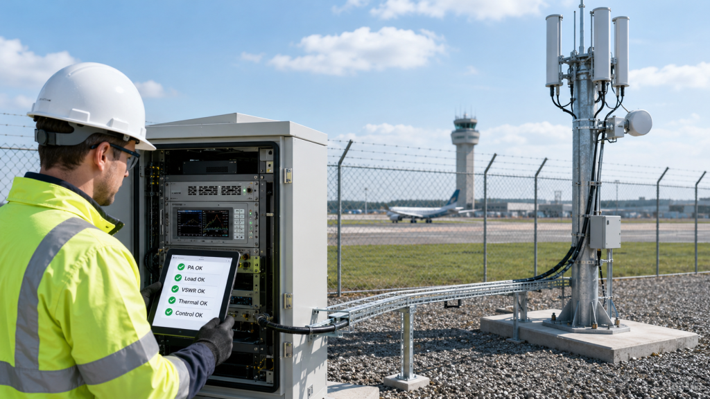
5. What RF Power Amplifier Antenna Load Reveals in C-UAS
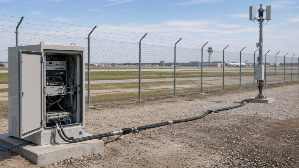
Real C-UAS deployments reveal that RF Power Amplifier load conditions change with site layout, antenna position, feeder routing, connector quality, vibration, and multi-module operation. A bench test removes these variables. A deployed system puts them back into the RF chain, which is why load coordination becomes a field reliability issue rather than a theoretical RF topic.
In an airport counter-UAS RF deployment, remote antennas, outdoor connectors, and longer feeder paths can change antenna-end power and reflected-power behavior. For a critical infrastructure Counter-UAS deployment, the same load uncertainty may become a remote maintenance problem because a vague alarm can be misread as PA failure, antenna failure, supply instability, or thermal stress.
Which deployment scenarios expose the risk?
The same PA module can face very different load conditions depending on where it is installed. The point is not to list scenarios, but to identify what each one changes in the RF chain.
Typical examples include:
- Airport perimeter systems with long outdoor feeder paths
- Critical infrastructure sites with remote cabinets
- Vehicle-mounted systems with vibration and cable strain
- Multi-band systems with several antenna paths
- Temporary deployments using changing cables and antennas
What does this mean for acceptance?
Acceptance should define where performance is measured. If the target is antenna-port behavior, a PA-port test alone cannot prove the full result. For fixed-site systems, antenna distance affects RF Power Amplifier selection because feeder length changes loss, reflected power, and the real load seen by the PA.
Key Takeaway: Field deployment turns antenna load from an RF parameter into a system reliability, maintenance, and acceptance issue.
| Deployment Type | Load Coordination Risk | Practical Check |
|---|---|---|
| Airport fixed site | Long feeder and outdoor joints | Review loss and reflection |
| Critical infrastructure | Remote troubleshooting | Separate alarm types |
| Vehicle platform | Vibration and cable movement | Test under movement |
| Temporary site | Variable antenna paths | Document each setup |
This table links real deployment conditions to the load checks that prevent late-stage confusion.
6. How Does Antenna Load Affect Heat, Supply, and Control?
Antenna load affects heat, supply, and control because RF Power Amplifier mismatch can change reflected power, current demand, protection status, and hot-state behavior. Load is not only an RF output issue. It can affect thermal margin, DC supply stability, and the way the controller interprets module status.
If the system is already close to its thermal or supply boundary, a small load problem can become a larger reliability problem under long duty cycle. This is why load mismatch should be reviewed with RF Power Amplifier thermal design and RF Power Amplifier power supply stability instead of being treated as an antenna-only concern.
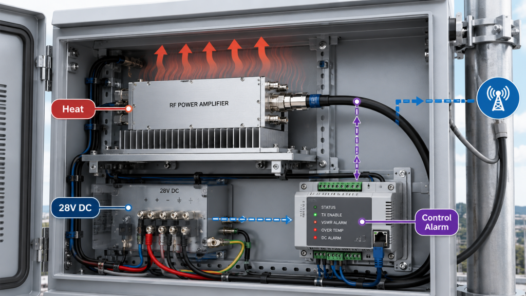
Where do the pressures connect?
Load mismatch can push several subsystems at once. That is why PA, antenna, cooling, supply, and control should not be reviewed in separate silos.
Important checks include:
- Reflected power under real load
- Temperature rise during duty cycle
- Module-terminal voltage under load
- Current behavior during enable
- Alarm type and trigger condition
- Cooling path after cabinet closure
- Controller response to protection
How should the controller support the review?
The RF Power Amplifier control logic should distinguish VSWR, temperature, voltage, and control feedback instead of treating every event as one alarm. A more detailed control interface helps the system decide whether to continue, reduce output, stop, log a service event, or request field inspection.
Key Takeaway: Antenna-load coordination protects more than RF output; it reduces false diagnosis across heat, supply, and controller behavior.
| Alarm Seen by Controller | Possible Real Cause | Wrong Action | Better Action |
|---|---|---|---|
| VSWR alarm | Antenna or feeder mismatch | Replace PA first | Sweep antenna path |
| Temperature alarm | Load + cabinet heat | Lower power only | Check cooling and reflection |
| Voltage alarm | Supply drop under load | Blame antenna | Measure module-terminal voltage |
| General PA alarm | Mixed fault causes | Guess by symptom | Separate alarm categories |
This table helps field teams avoid replacing the wrong part when load, heat, power, and control symptoms overlap.
7. Which Coordination Path Fits Your System?
The right coordination path depends on risk because RF Power Amplifier antenna-load review can range from PA-only verification to full RF chain validation. A lab evaluation does not need the same process as a 24/7 fixed-site C-UAS rack. A multi-module airport, border, or critical infrastructure system should not be approved with the same evidence as a single dummy-load test.
Here’s the engineering point: the depth of coordination should match the cost of field failure. If access is easy, the load is fixed, and the duty cycle is low, a lighter path may work. If the system is remote, high-power, wideband, or multi-module, stronger coordination is safer.
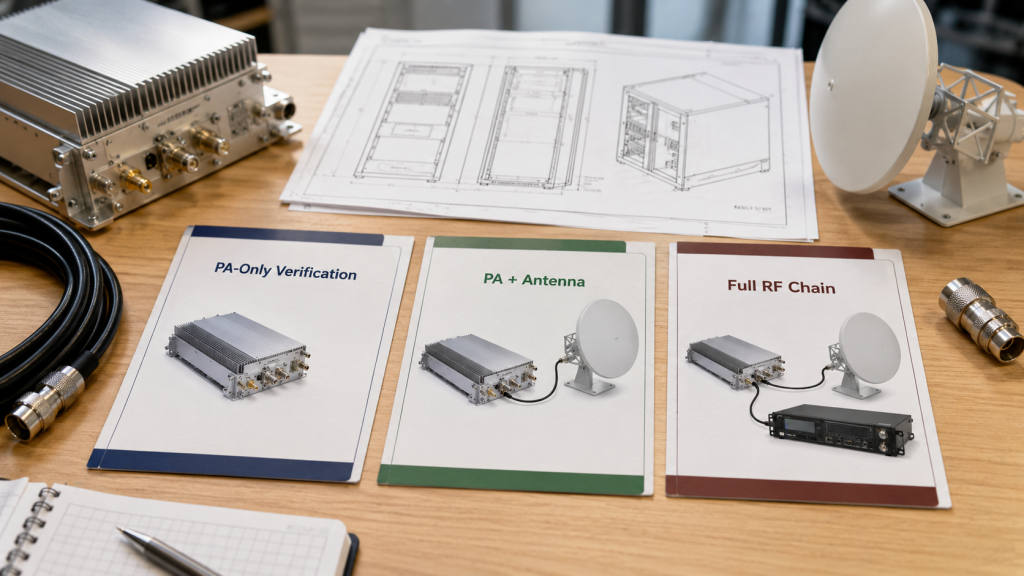
What are the three practical paths?
You can separate projects into three levels before sample approval. This prevents both under-testing and unnecessary complexity.
The three paths are:
- PA-only verification
- PA + antenna coordination
- Full RF chain coordination
How should buyers choose?
Choose based on what must be proven. PA-only tests prove module capability. PA + antenna tests prove load behavior. Full RF chain coordination proves readiness of the installed system, including antenna path, feeder loss, connectors, adapters, thermal margin, DC supply, and controller response.
Key Takeaway: The best coordination path is not always the most complex one; it is the one that matches field risk and acceptance responsibility.
| Coordination Path | Best Fit | Main Limitation |
|---|---|---|
| PA-only verification | Lab or fixed load | Does not prove field load |
| PA + antenna | Most C-UAS projects | May miss supply/control links |
| Full RF chain | Mission-critical sites | Requires more planning |
| Retest after changes | Any modified system | Must match previous evidence |
This table gives procurement and engineering teams a practical way to choose validation depth.
8. How to Include RF Power Amplifier Load in Test Evidence
Test evidence should include load conditions because RF Power Amplifier output, reflected power, alarms, temperature, current, and repeatability cannot be judged without knowing the load path. A report that only shows power without stating the load condition leaves too much room for interpretation. You need to know whether the test used a 50Ω load, real antenna, system-equivalent load, or full RF chain.
This is where test evidence becomes more than paperwork. If the customer retests with a different cable, adapter, antenna, or reference point, the result may change even when the PA module is unchanged. A repeatable RF Power Amplifier test evidence approach should record the load condition, not only the final wattage number.

What should the report record?
A useful report should make the test condition reproducible. It does not need to become a long textbook, but it should contain enough information for a second engineer to rebuild the setup.
Useful evidence includes:
- Load type
- Output reference point
- Forward power
- Reflected power
- VSWR state
- Voltage and current
- Temperature
- Protection status
- S/N and hardware version
How should protection evidence be interpreted?
Protection evidence should connect the alarm to the load condition. If the report only says “alarm,” the controller team cannot decide whether the event came from antenna mismatch, heat, voltage, or logic state.
Key Takeaway: Test evidence becomes system-level evidence only when the load path and protection behavior are documented together.
| Report Item | Must State | Why It Matters |
|---|---|---|
| Load type | 50Ω / antenna / full RF chain | Defines test meaning |
| Reference point | PA port / cable end / antenna port | Prevents power disputes |
| Reflected power | Value or alarm state | Shows mismatch risk |
| Protection status | VSWR / temperature / voltage | Supports root-cause review |
| S/N and version | Unit-specific evidence | Supports retesting |
This table gives buyers a clearer way to judge whether a test report can support field acceptance or only module-level approval.
9. What RF Power Amplifier Load Data Buyers Should Share
Buyers should share RF Power Amplifier load information before RFQ so the supplier can judge real system risk instead of quoting only against a dummy-load assumption. Asking only for frequency, wattage, voltage, and price is not enough for serious C-UAS integration. The supplier also needs to understand the load path that the PA will see after installation.
The better check is simple: if the supplier does not know the antenna path, it can only make assumptions about reflected power, feeder loss, protection behavior, heat, and controller feedback. Even when module output is stable, RF Power Amplifier feeder cable loss can change antenna-port power and should be reviewed with load matching and protection behavior.
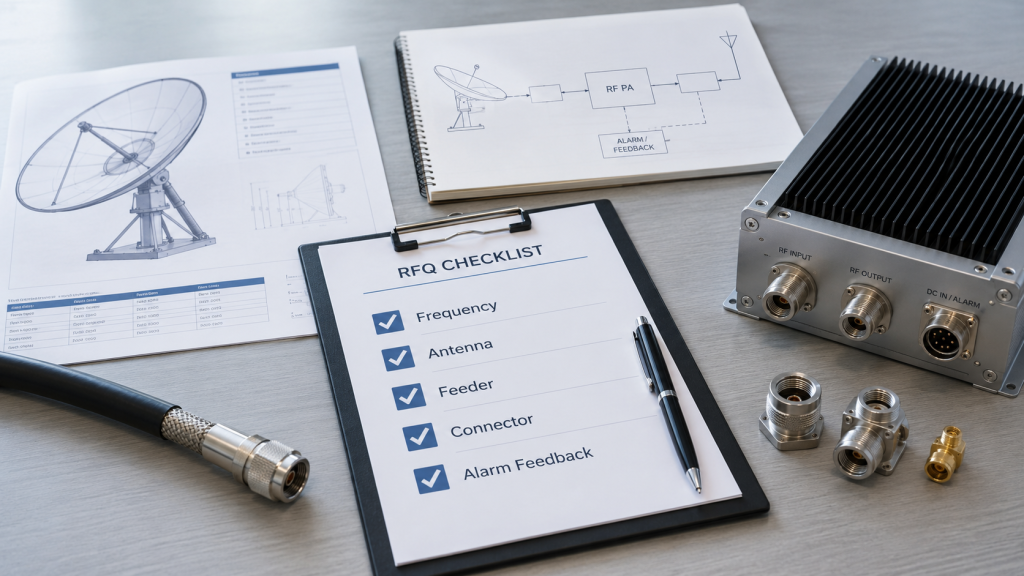
What should be included in the RFQ?
A useful RFQ does not need every detail on day one, but it should give enough context to avoid wrong selection. Early incomplete information is still better than no load information.
Share these items when available:
- Target frequency range
- Target output reference point
- Antenna type or model
- Antenna VSWR or return loss
- Feeder cable type and length
- Connector and adapter count
- Waterproof joint or arrester use
- Vehicle or fixed-site installation
- Duty cycle
- Ambient temperature
- Supply margin
- Cooling method
- Required alarm feedback
What if the antenna is not final yet?
If the antenna is not final, state the planned load boundary and expected test method. The antenna load path should also include RF cable grade for RF Power Amplifiers and possible RF Power Amplifier adapter errors, because cables, adapters, and connector transitions can change both field load behavior and retest results.
Key Takeaway: Better RFQs reduce late redesign by giving the PA supplier enough load, feeder, thermal, supply, and control context before quotation.
| RFQ Item | Why It Matters | Risk If Missing |
|---|---|---|
| Output reference point | Defines success location | Power disputes |
| Feeder length | Changes loss and load | Weak antenna-end output |
| Antenna match data | Predicts reflection | VSWR alarms |
| Alarm feedback need | Defines control action | Blind fault handling |
This table turns load coordination into a practical procurement checklist.
10. What Proves RF Power Amplifier and Antenna Load Fit
PA and antenna load are coordinated when RF Power Amplifier output reference point, load path, mismatch risk, protection behavior, thermal margin, supply margin, controller logic, and test evidence are reviewed together. Coordination is not one measurement. It is a chain of decisions that makes the module result and field result easier to connect.
For an RF engineer, the final question is not “Did the PA pass?” The better question is: “Did the PA pass under the load condition that represents the system we are building?” As a source factory for RF Power Amplifier modules and C-UAS core components, RF SKYPOWER can support early engineering review by checking PA module selection, antenna path, feeder conditions, thermal margin, supply margin, protection feedback, and repeatable evidence before final system integration.
What should the final review confirm?
The final review should connect RF, mechanical, thermal, electrical, and control conditions. If one part changes later, the related checks should be repeated.
A practical final checklist includes:
- PA-port or antenna-port target
- Complete load path
- Frequency-specific match
- Feeder loss estimate
- Reflected-power behavior
- Thermal condition under duty cycle
- Module-terminal voltage
- Alarm type and controller action
- Test setup and S/N traceability
- Retest plan after system changes
Where does source-factory support help?
Source-factory support helps most when the project is still flexible enough to change antenna path, cable routing, cooling, DC supply, or controller feedback. If the supplier only joins after field alarms begin, the work becomes troubleshooting instead of prevention.
Key Takeaway: Proper coordination means the PA is not approved as an isolated part; it is approved as a controlled component inside a defined RF chain.
| Final Review Area | Coordinated Condition | Warning Sign |
|---|---|---|
| Output target | Reference point defined | “100W” without location |
| Load path | Antenna chain documented | Unknown connectors |
| Protection | Alarm type separated | One vague fault signal |
| Evidence | Retestable setup recorded | Report lacks conditions |
This table gives procurement and engineering teams a final gate before sample approval or deployment.
FAQ
Can I approve a PA module based only on a 50Ω test?
Yes, but only for module-level approval. A 50Ω test is valid for controlled PA verification, but it does not prove antenna-load behavior, feeder loss, reflected power, or field alarm stability.
What should I check before connecting a real antenna?
Start with the load path. Confirm antenna match, feeder cable length, connector count, adapter use, output reference point, VSWR protection behavior, and controller alarm visibility before full operation.
How do I know if the issue is PA failure or antenna load?
Compare the PA on a controlled load against the real RF chain. If the PA is stable on a 50Ω load but alarms or drops output with the antenna path, inspect mismatch, cable loss, connectors, adapters, and installation effects.
When should I request full RF chain coordination?
Request full RF chain coordination when the system is high-power, wideband, remote, multi-module, vehicle-mounted, or mission-critical. These conditions make late troubleshooting slower and more expensive.
What load information should be included in a test report?
A useful report should state load type, reference point, forward power, reflected power, VSWR state, temperature, voltage, current, protection status, S/N, hardware version, and test setup conditions.
Conclusion
RF Power Amplifier design should not be separated from antenna load. A 50Ω bench load proves controlled module capability, but real C-UAS deployment depends on antenna matching, feeder path, connector quality, reflected power, thermal behavior, supply margin, and controller feedback. If the PA module is approved without load coordination, field alarms may later appear as VSWR events, thermal stress, voltage instability, unclear controller status, or repeated retesting disputes.
For system integrators, RF engineers, and procurement reviewers, the practical lesson is clear: define the load path before final PA approval. Confirm the output reference point, antenna type, feeder length, connector path, mismatch behavior, reflected power, thermal margin, supply margin, protection feedback, and test conditions. RF Power Amplifier performance should be judged as part of the RF chain, not only as a standalone module.
RF SKYPOWER supports early coordination between PA modules, antenna systems, feeder paths, cooling, supply, and controller logic for authorized C-UAS and RF system integration projects. If your project has not yet aligned antenna load, reflected-power risk, thermal margin, supply margin, and status feedback, you can contact us today to review the load path before final approval.
A field-ready C-UAS RF chain is not approved by a clean dummy-load number; it is approved when the PA, antenna load, feeder path, protection logic, and test evidence all describe the same system.