










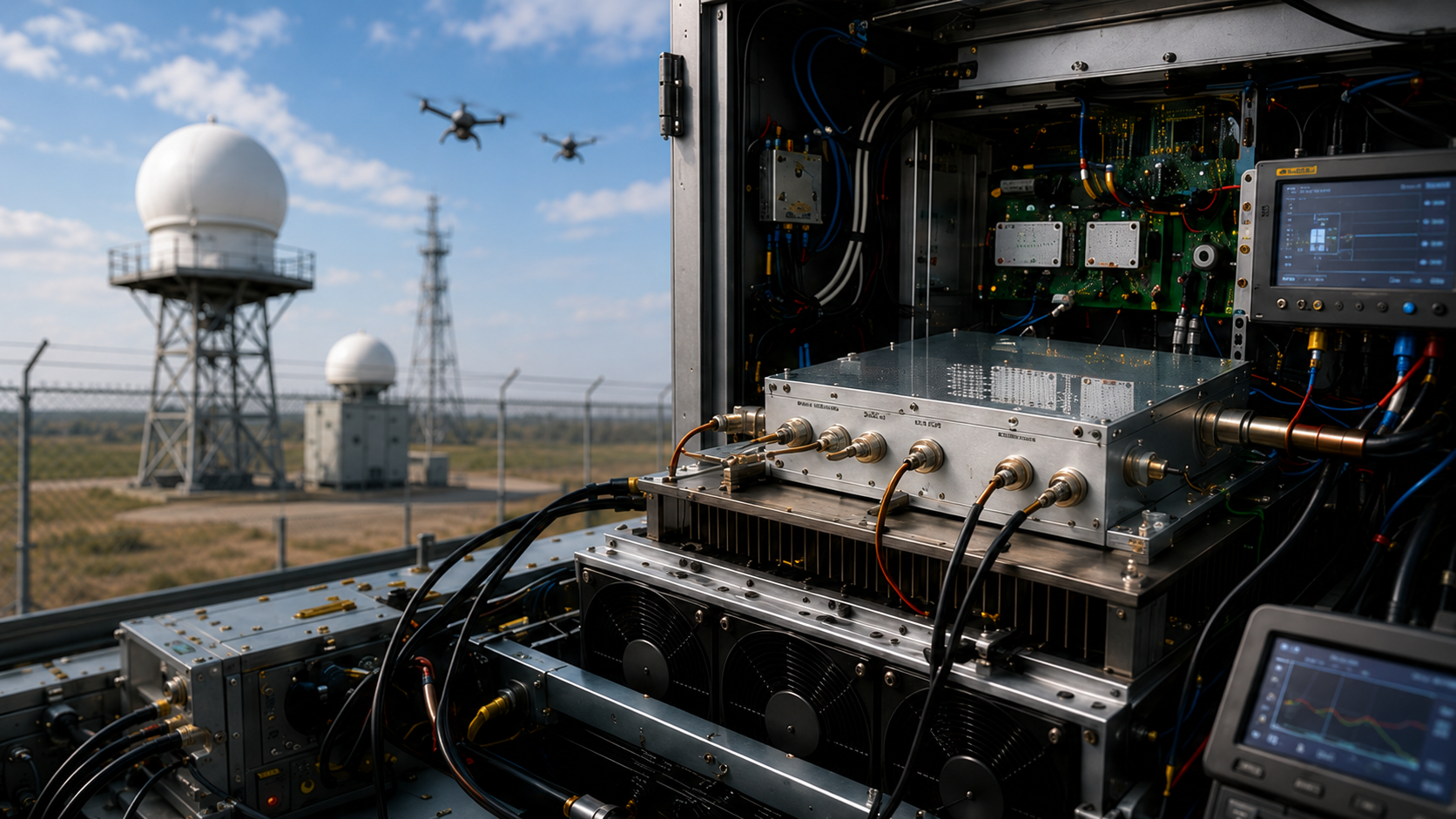
RF PA thermal design should be approved only after the complete heat-removal path and the hot-state test boundary are clearly defined. A large heatsink or normal cold-start RF output does not by itself show that a high-power C-UAS PA will remain stable after heat moves through the RF device, package, PCB or carrier structure, module baseplate, thermal interface, external heatsink, cabinet airflow, and final installation environment.
The common mistake is to review cooling components separately. A heatsink may look adequate, a fan may move air, and a short bench test may reach the required RF output power (Pout), yet those observations are not directly comparable unless they come from the same frequency, output requirement, duty cycle, module-terminal voltage, load condition, ambient or inlet temperature, cooling configuration, temperature measurement point, stabilization rule, and RF output reference plane.
The first decision is therefore not “Which heatsink is bigger?” It is whether the thermal boundary has been defined well enough to compare supplier evidence, approve the design, and write an RFQ that represents the installed operating condition.
1. What Must Be Defined Before RF PA Thermal Design Can Be Approved?
Thermal approval needs three boundaries to agree: the RF operating point, the cooling boundary, and the evidence used for the decision.
The RF operating point should identify the required frequency or frequency points, RF output and measurement reference plane, actual input-drive or control state where relevant, module-terminal Vdc, Idc, duty cycle or waveform, and load or VSWR condition. The amount of heat that must be removed depends on DC input and RF output at the same operating point. If the efficiency definition or electrical boundary is unclear, the thermal design input is also incomplete.
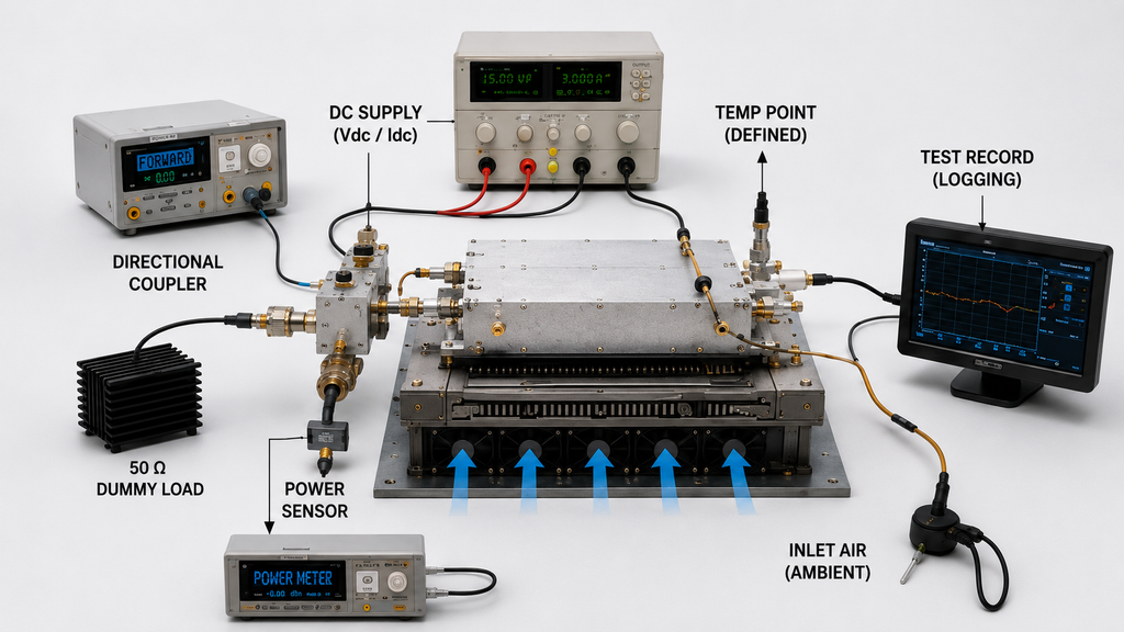
The cooling boundary should state how heat leaves the module. That includes the mounting surface, thermal interface, external heatsink or cooling plate, airflow condition, cabinet state, and ambient or inlet-air temperature that apply to the evidence being reviewed. An open-bench result and a closed-cabinet result may both be valid, but they do not describe the same thermal boundary unless the differences are explicitly reconciled.
The evidence boundary should define what is measured, where it is measured, when the result is taken, and what acceptance limit applies. A temperature value needs a defined measurement point. A hot-state result needs a defined test duration or stabilization rule. A power result needs a defined RF reference plane. Protection status should also be recorded when protection behavior is part of the approval requirement.
If these material conditions are not aligned, do not approve or reject the PA from one temperature or power number alone. First align the test conditions or request the missing evidence.
2. What Thermal Path Must Be Defined From Device to Cabinet?
A high-power RF PA does not reject heat through one component. The practical path can include:
- RF power device and package
- PCB copper, thermal vias, carrier, or internal heat spreader
- Module baseplate
- Thermal interface material
- External heatsink, cooling plate, or mounting structure
- Cabinet cooling air
- The external installation environment
Each part has a different job. Internal copper or a carrier spreads concentrated heat. The baseplate transfers heat toward the external interface. The thermal interface fills microscopic gaps between mating surfaces. The heatsink expands the area available for heat rejection, while the cabinet airflow or other cooling method carries that heat away.
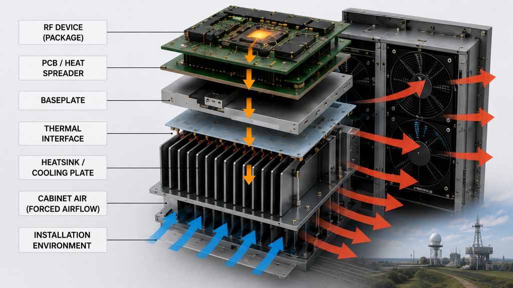
This is why visible heatsink size is not enough for thermal approval. A larger heatsink cannot correct poor internal heat spreading or an uncontrolled mounting interface. Strong airflow cannot correct an air gap between the module baseplate and the mounting surface. Likewise, a well-designed module can still run hot when the installed cabinet changes the airflow, inlet temperature, or heat rejection path assumed during testing.
For approval, the buyer does not need the current page to become a complete TIM, mounting, or RF PA heatsink design tutorial. The necessary question is whether the supplier has defined the internal path to the baseplate, the required module-to-cooling interface, and the external cooling condition represented by the evidence.
3. Where Does Module Thermal Design End and Cabinet Cooling Begin?
The boundary between module thermal design and cabinet cooling should be agreed before results are compared. It does not automatically end at the module baseplate.
A supplier test may use a specified mounting plate, a reference heatsink, forced airflow, or an open-bench arrangement. The final C-UAS installation may use a different heatsink, fan path, filter, enclosure, module spacing, orientation, or cabinet inlet temperature. If the test boundary changes, the thermal result may change even when the PA module itself is unchanged.
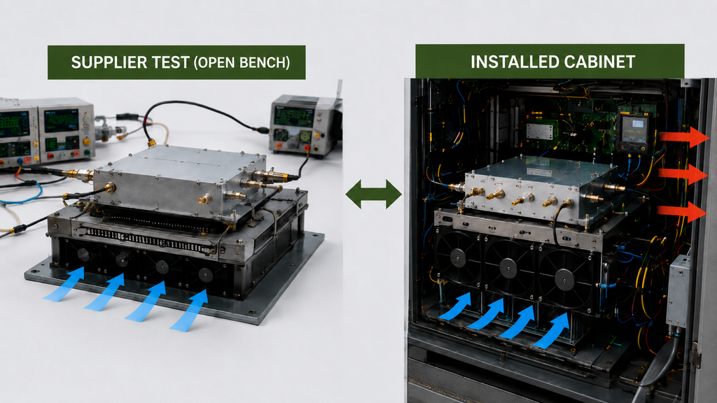
The approval record should therefore identify what the supplier evidence actually included:
- the module mounting surface and orientation;
- the thermal-interface condition where it affects the test boundary;
- the heatsink, cooling plate, or reference cooling structure;
- the airflow or fan condition;
- the ambient or inlet-air temperature;
- whether the test was open-bench, closed-cabinet, or another defined configuration.
This separates responsibility without assigning every thermal problem to either the supplier or the integrator in advance. Factory and installed-system results can both be legitimate while still representing different boundaries.
If the final cabinet differs materially from the supplier test, the next step is to reconcile those differences or validate the installed cabinet airflow boundary. Do not treat a change in cabinet airflow or mounting condition as proof of a PA defect, and do not treat a factory pass as automatic proof of the final cabinet.
4. Which Operating Conditions Make Thermal Evidence Comparable?
Thermal evidence becomes useful for supplier comparison only when the conditions that can change heat generation or heat removal are aligned closely enough for the intended decision.
The comparison should identify, as applicable:
- frequency or required frequency points;
- RF output requirement and measurement reference plane;
- actual input drive, gain state, or control state where relevant;
- module-terminal Vdc and measured Idc;
- duty cycle, waveform, or transmit pattern;
- load condition and relevant VSWR boundary;
- ambient or cabinet inlet-air temperature;
- mounting, TIM, heatsink, or cooling-plate condition;
- airflow, fan state, and cabinet configuration;
- test duration or thermal-stabilization rule;
- temperature measurement point and attachment method when temperature is compared;
- protection state, including whether the PA remained in normal operation or entered an alarm, foldback, or shutdown state.
GaN-based and other high-power-density PA designs make this condition matching more important, not less. High power density can concentrate heat in smaller regions, but that does not make GaN inherently unreliable; it makes the operating and cooling boundary important to the result. For wideband operation, efficiency, current, gain, and thermal behavior can also change with frequency and output operating point. A center-frequency cold test should therefore not be treated as full evidence for every project frequency or hot-state condition.
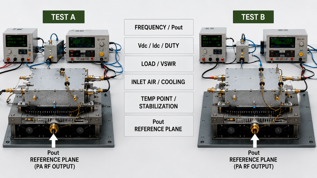
The same rule applies to temperature. A module-case reading, baseplate reading, heatsink reading, and cabinet-air reading describe different points in the thermal system. They should not be ranked as if they were the same measurement unless the relationship between the points and the surrounding test boundary is defined. If temperature values are compared between supplier and installed tests, define the temperature probe location before treating the readings as the same thermal metric.
When material conditions differ, the results may still help identify what needs further testing, but they should not be used for a final supplier ranking or pass/fail decision until the relevant conditions are aligned or reconciled.
5. What Hot-State Evidence Is Required Before Approval?
When hot-state performance is part of the project requirement, the evidence should answer one practical question: after heat has accumulated under the defined operating and cooling boundary, does the PA still meet the agreed RF, DC, thermal, and protection limits?
A cold-start screenshot is a useful functional baseline. It does not establish stabilized performance. When the purpose is to separate cold-start output from stabilized performance, a defined RF PA thermal soak can provide the required hot-state evidence.A hot-state record should state how the test reached its decision point, either through a defined operating duration, a defined stabilization rule, or another agreed condition.
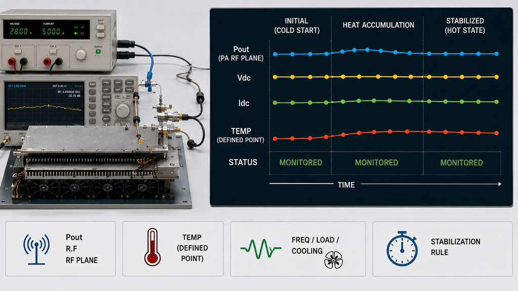
Depending on the approval requirement, useful hot-state evidence can include:
- initial and stabilized RF output;
- the frequency or frequency points used;
- Vdc and Idc during the same operating interval;
- ambient or inlet-air temperature;
- the defined case, baseplate, heatsink, or other temperature measurement point;
- cooling and airflow condition;
- load or VSWR condition;
- test duration or stabilization criterion;
- alarm, foldback, shutdown, or recovery status where applicable.
The RF output boundary must also stay clear. PA-port Pout should not be confused with antenna-end power when feeder cables, connectors, filters, lightning protection, or other RF-path losses are included downstream. If the project uses antenna-end acceptance, the RF path and its corrections need their own defined boundary.
If some hot-state derating is allowed, the permitted reduction, baseline, minimum acceptable output, thermal condition, and decision rule should be defined before the result is judged. A lower hot-state number is not automatically a failure if the agreed requirement permits it, just as a stable temperature value is not automatically a pass if it was measured at the wrong point or under an easier cooling condition.
6. How Should Thermal Evidence Scope Match the Approval Requirement?
Thermal evidence should support only the scope it actually covers. A result from one unit should not be extended automatically to a full batch, and a batch or configuration result should not be presented as delivered-unit evidence unless the agreed acceptance structure allows that use.
Projects may use different evidence scopes. For example:
- project-level requirements define the operating, thermal, reference-plane, and acceptance boundaries;
- type- or configuration-level evidence can support a defined design or approved configuration;
- batch-level evidence can support a stated production lot or sampling plan;
- per-unit evidence can link a specific result to a delivered serial number.
The exact terminology and required evidence scope should follow the RFQ or the agreed C-UAS RF PA acceptance checklist. The important rule is that the evidence scope and the decision use must match.
| Buyer Requirement | Required Evidence | Required Condition | Evidence Scope | Decision Use |
|---|---|---|---|---|
| Establish the heat-removal input | Matched RF output and DC operating data, with the efficiency or electrical boundary identified where used | Same frequency, output state, duty cycle, and electrical reference boundary | Project, configuration, or tested-unit scope as applicable | Define the cooling design input without mixing incompatible efficiency or power data |
| Approve the installed cooling boundary | Defined mounting, heatsink or cooling structure, airflow condition, ambient or inlet condition, and hot-state result | Same or explicitly reconciled installation boundary | Project or configuration scope; per-unit only when required | Decide whether the evidence represents the intended installation |
| Approve hot-state RF performance | Stabilized Pout with relevant Vdc, Idc, temperature, load, and protection data | Defined frequency, duty, cooling condition, stabilization rule, and RF reference plane | Per-unit, batch, or configuration scope as specified | Approve, hold, or request retest against the agreed thermal requirement |
| Compare temperature results | Temperature trend with exact measurement point and attachment method | Same or reconciled measurement point and operating condition | Scope of the stated test record | Decide whether two temperature results are technically comparable |
| Use thermal or protection evidence for release | Test record with applicable limits and protection status | Defined thermal state, trigger or limit, and acceptance condition | Configuration, batch, or per-unit scope as specified | Support the release decision only within the agreed evidence scope |
| Require delivered-unit traceability | Dataset or report linked to the delivered serial number | Unit-level evidence must be explicitly required by the acceptance plan | Per-unit | Trace the stated result to the physical delivered module |
This prevents two opposite errors. Buyers should not accept a broad claim from evidence that covers only a narrower scope, but they also should not require every thermal or stress test to be repeated for every S/N when the agreed project structure defines a different valid evidence scope.
If the evidence scope is missing or ambiguous, clarify it before using the result for shipment release, supplier comparison, or final approval.
7. What Thermal Requirements Belong in the RFQ?
Thermal requirements should be defined before the supplier recommends a final PA route, because the same RF output target can lead to different cooling and evidence requirements under different duty cycles, ambient conditions, installation boundaries, and acceptance rules.
For a high-power C-UAS RFQ, define the inputs that materially change the thermal decision:
- required frequency range or exact operating frequency points;
- required RF output and whether it is defined at the PA port or another reference plane;
- duty cycle, waveform, or expected transmit pattern;
- module-terminal DC voltage and the required operating condition;
- load condition and applicable VSWR boundary;
- ambient or cabinet inlet-air condition;
- cabinet, vehicle, outdoor, or other relevant installation boundary;
- responsibility for the external heatsink, cooling plate, mounting surface, TIM, and airflow;
- temperature measurement point and attachment method when temperature limits are part of acceptance;
- hot-state test duration or stabilization rule;
- permitted derating, alarm, foldback, shutdown, or recovery limits where applicable;
- required evidence scope, such as project-, configuration-, batch-, or per-unit evidence;
- required report fields and the pass, review, hold, or retest rule.
These inputs should guide product discovery rather than be added after a module is already selected. A wide frequency range or a high nominal power rating does not by itself establish thermal suitability for the installed C-UAS system.
When a standard product family does not match the required frequency, output, voltage, cooling, interface, or evidence boundary, Custom RF Power Amplifier Modules may provide the appropriate engineering/RFQ route. That is a product-discovery step, not proof that a specific model will meet the project requirement.
Conclusion
RF PA thermal design for a high-power C-UAS module should be approved only when the complete heat path, installation cooling boundary, operating condition, measurement reference points, hot-state decision rule, and evidence scope are defined together. A large heatsink, a room-temperature reading, or a cold-start Pout can support part of the review, but none of them alone proves installed hot-state performance.
This framework helps determine whether the available evidence is fit for comparison and approval. It does not replace project-specific acceptance limits, final installed-system validation, or per-unit evidence when the RFQ specifically requires delivered-unit traceability. The most common misinterpretation is to treat one “good” temperature or output result as general proof across different frequencies, duty cycles, ambient conditions, cooling boundaries, or evidence scopes.
Before comparing suppliers, write the thermal acceptance boundary in one place: frequency, RF output reference plane, duty cycle, module-terminal Vdc, load or VSWR condition, ambient or inlet temperature, mounting and cooling condition, temperature measurement point, stabilization rule, and required evidence scope. Then compare results only against that agreed boundary.
If your team is preparing an RFQ and the required operating frequencies fall within a listed Wideband RF Power Amplifier Modules family, send RF SKYPOWER the defined thermal inputs for engineering review and product-route discussion. Any product suitability or acceptance decision should remain tied to the actual project conditions and the evidence available for that scope.