










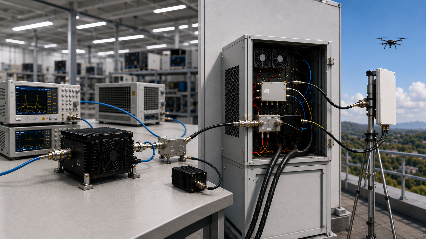
Here, anti-drone signal quality means repeatable RF output behavior at a defined measurement boundary and under defined operating conditions. It does not substitute for separate spectral, modulation, radiated-coverage, or operational-effectiveness verification.
A module can meet its RF output requirement at the PA output reference plane and still produce a different installed result after feeder loss, connector transitions, antenna mismatch, cabinet heat, DC drop, or protection behavior are included. For that reason, rated power, advertised range, or a single test screenshot should not be treated as sufficient proof by themselves.
Before RFQ or before using test evidence in an acceptance decision, define what is being verified, where it is measured, which frequency points and operating states apply, and what evidence scope is required. If critical conditions are missing, the correct conclusion is not “pass” or “fail”; it is cannot conclude yet.
1. What “Signal Quality” Should Mean for an Anti-Drone RF Module
For buyer-side RF evaluation, signal quality should be treated as a conditional acceptance claim rather than a general marketing description.
The practical question is:
Does the module produce the required RF output behavior at the agreed frequency points, reference plane, input-drive condition, load, DC condition, thermal state, and duty cycle?
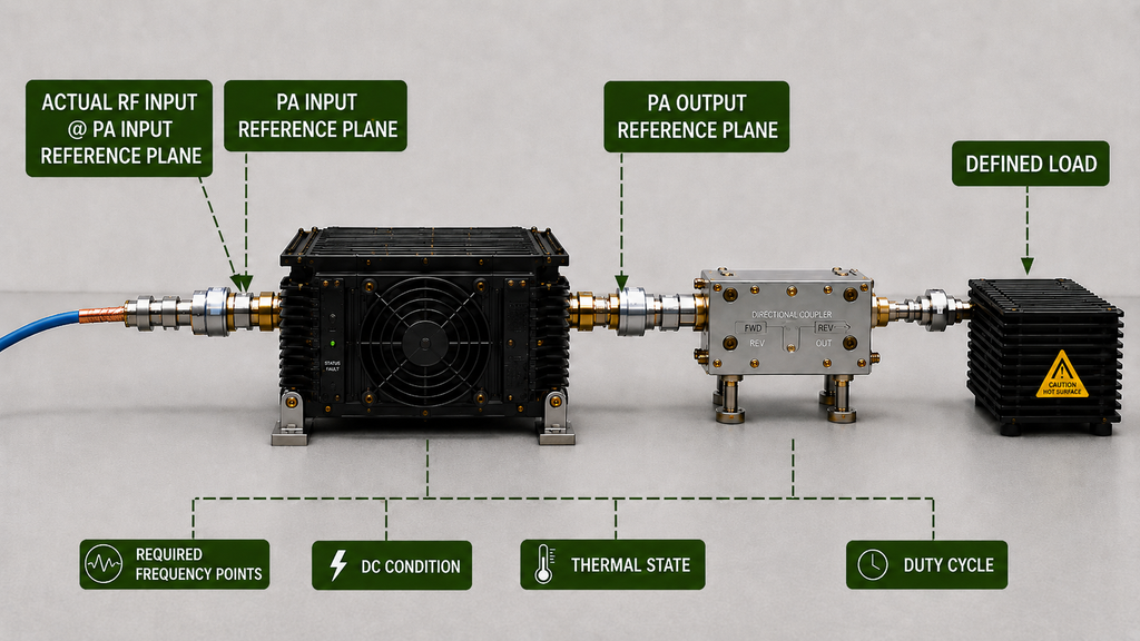
This definition is more useful than a general statement such as “stable signal” because it forces the buyer and supplier to identify the conditions that make the result comparable.
For example, the signal-generator setting should not automatically be treated as the actual RF input power at the PA input reference plane. Likewise, a PA-port output result should not automatically be treated as antenna-end power.
The project should also define what “stable” means. Depending on the requirement, this may include output remaining within agreed limits at specified frequency points, repeatable behavior at the required thermal state, or no unexpected protection behavior under the defined load.
Those limits must come from the product specification, RFQ, or approved acceptance requirement. They should not be invented from a generic article.
A module-level result also has a clear boundary: it may support a module-level RF decision under the recorded conditions, but it does not by itself prove complete installed C-UAS performance.
2. Why the Measurement Boundary Changes the Verdict
A signal-quality result only has meaning when its measurement boundary is clear.
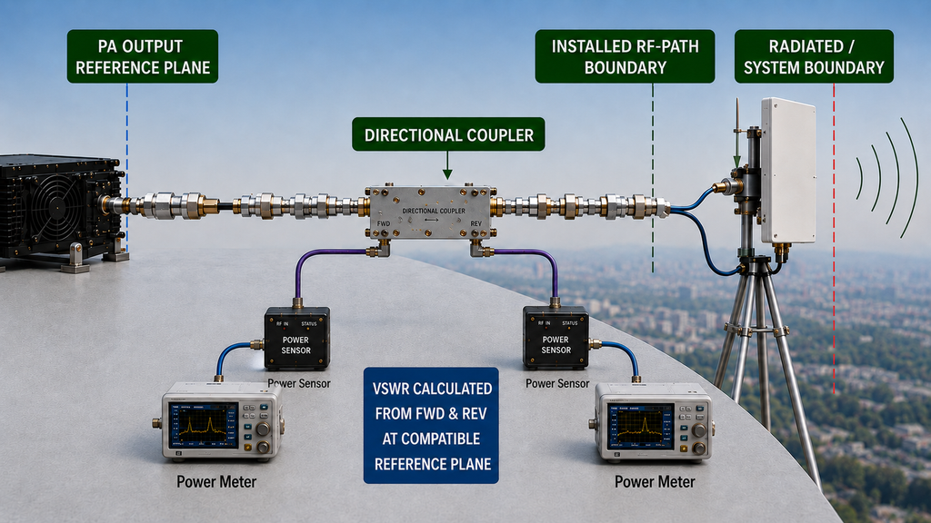
Three different boundaries are commonly confused:
- PA output reference plane: RF output is evaluated at the module output under a defined test condition.
- Installed RF-path boundary: feeder cable, connectors, switching or protection hardware, and antenna/load conditions are included up to an agreed measurement point.
- Radiated or system boundary: antenna radiation, propagation, installation geometry, interference, and other system-level effects are included.
These boundaries answer different questions.
A PA-port result and an installed-path result should therefore remain tied to their own reference plane, correction method, load, and operating condition. A raw instrument reading should also not be treated as equivalent to a corrected reference-plane result unless the correction basis is stated.
FWD, REV, or VSWR data may help determine whether mismatch is involved, but they do not automatically identify the root cause. A change in reflected power can justify further isolation; it does not, by itself, prove whether the cause is the antenna, feeder, connector, adapter, protection device, or another part of the RF path.
The buyer-side decision rule is simple:
If the reference planes or critical test conditions do not align, do not treat the two RF values as directly comparable yet.
3. Define the Acceptance Boundary Before RFQ
The strongest time to define signal-quality acceptance is before the supplier quotes the module.
Frequency range and rated output power alone leave too much room for different interpretations of the test. A useful RFQ should define the conditions that determine whether the signal-quality requirement has actually been demonstrated.
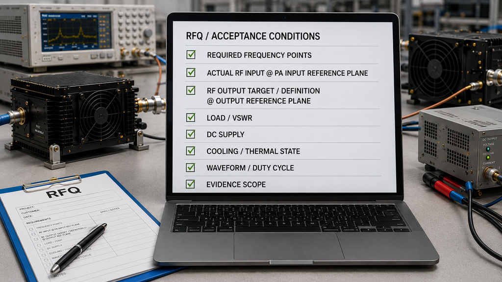
Relevant inputs may include:
- required frequency points or agreed sweep range;
- waveform and duty cycle used for verification;
- actual RF input power at the agreed PA input reference plane;
- RF output definition and output reference plane;
- normal load condition and any required mismatch or VSWR boundary;
- DC supply condition and applicable voltage reference point;
- cooling condition and required thermal state;
- protection, alarm, foldback, shutdown, or recovery behavior relevant to the requirement;
- required evidence format and evidence scope.
The RFQ should also distinguish module-level evidence from installed-path evidence.
If the project requires a PA-port result, state that reference plane. If it also requires evidence after a defined feeder or installed RF path, state that separately. Do not blend both into one undefined “output power” requirement.
This becomes especially important when matching an RF power amplifier in a C-UAS RF chain that combines an SDR source, power supply, cooling structure, antenna path, or control system from different suppliers. Without a common boundary, an integration issue can easily be mislabeled as an RF PA signal-quality problem.
When a critical definition is missing—such as actual input drive, output reference plane, load condition, thermal state, or duty cycle—do not approve or reject the claim from the available number alone.
Define the missing condition first, then request aligned evidence.
4. What Evidence Is Sufficient to Support the Signal-Quality Claim
Evidence is useful only when it matches the claim, test conditions, and evidence scope required by the project.
A clean screenshot at one operating point may document that particular test condition. It does not automatically prove the required frequency range, hot-state behavior, mismatch condition, voltage condition, duty cycle, or another configuration that was not tested.
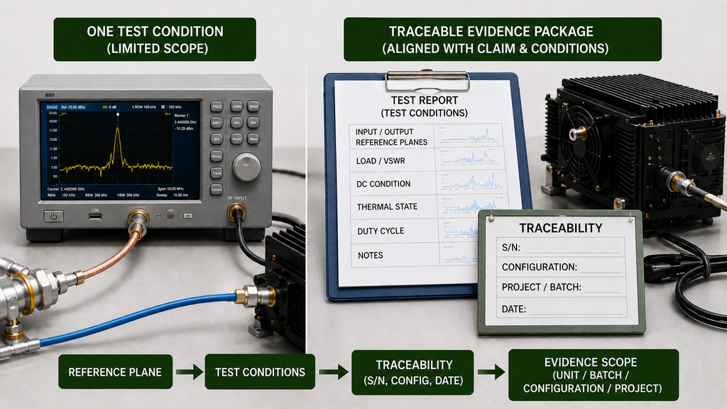
Depending on the agreed requirement, useful evidence may include:
- tested frequency points or sweep range;
- actual RF input power at the defined input reference plane;
- RF output at the defined output reference plane;
- whether the reported result is raw or corrected;
- FWD, REV, or VSWR information when mismatch behavior is relevant;
- Vdc and Idc at the applicable operating state;
- load or installed RF-path condition;
- cooling condition, temperature reference, and thermal state;
- waveform and duty cycle;
- relevant protection or alarm state;
- serial number, batch, configuration, project identifier, or other traceability required by the agreed evidence scope;
- the resulting judgment against the agreed signal-quality requirement.
Evidence scope must be stated explicitly.
Depending on the approved RFQ or acceptance plan, valid evidence may apply to a specific unit, batch, configuration, or project. A serial-number-linked report is strong evidence for the unit it identifies, but it should not automatically be generalized to a batch or another configuration unless the approved evidence structure supports that broader scope.
The same principle applies when comparing supplier reports.
A higher reported output value is not automatically a better result when the reports use different input drive, reference planes, power definitions, loads, correction methods, thermal states, or duty cycles.
If the critical test conditions cannot be aligned, treat the supplier reports as not comparable yet; do not rank them by raw output power alone.
The practical buyer question is therefore not simply:
“Is there a test report?”
It is:
“Does this evidence prove the signal-quality requirement, under the conditions and evidence scope we actually agreed?”
5. When Thermal and Duty-Cycle Conditions Change the Verdict
Cold-state and hot-state results should not be treated as interchangeable.
If thermal condition or duty cycle is part of the acceptance requirement, the RF result should be verified within a defined full-power RF PA test boundary at the operating state required by the RFQ or acceptance plan. A short or low-duty bench result does not by itself prove stabilized hot-state behavior.
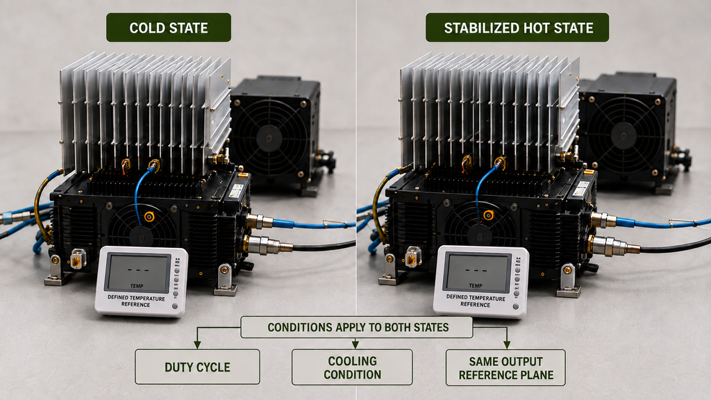
Output reduction, higher current, temperature change, reflected-power change, or protection activation are observations—not automatic proof of a thermal root cause.
If the RF result changes as the operating state changes, check the relevant cooling, RF load, DC supply, input drive, and protection conditions before assigning the cause.
The decision rule is again conditional:
A result can support the required signal-quality claim only when the thermal and duty-cycle state represented by the evidence matches the state required for that claim.
If the project requires hot-state evidence and only a cold-state result is available, the correct action is to request the missing hot-state evidence rather than assume equivalence.
6. Signal-Quality Evidence Mapping Before RFQ or Acceptance Use
The most useful buyer-side artifact is not a longer list of test items. It is a direct mapping between the requirement, the evidence, the condition under which that evidence is valid, and the decision it can support.
| Buyer Requirement | Evidence to Request | Required Test Condition | Evidence Scope | Decision Use |
|---|---|---|---|---|
| Required frequency-point RF output | Output data at the required points or agreed sweep | Defined waveform, actual input drive, load, and output reference plane | Scope defined by RFQ or acceptance plan | Check the RF result against the agreed signal-quality requirement |
| Measurement / installed-path boundary | PA-port and/or installed-path result, including applicable loss correction | Defined reference plane, RF path, load, and correction basis | Tested configuration or other approved scope | Determine what the reported RF value actually represents |
| Mismatch-related behavior | FWD/REV/VSWR and relevant protection-state record when required | Defined load or mismatch condition and measurement point | Scope defined by the agreed test plan | Support mismatch assessment and determine whether further isolation is needed |
| Thermal and duty-cycle behavior | RF output plus applicable temperature and operating-state record | Defined cooling, thermal state, test duration, waveform, and duty cycle | Unit/configuration/project scope as agreed | Determine whether the required operating state is supported |
| DC and control condition | Vdc/Idc plus relevant alarm, enable, ready, or protection state | Defined RF operating state and voltage reference point | Scope defined by RFQ or acceptance plan | Determine whether power or control condition affects the RF judgment |
| Traceable signal-quality evidence | Test record linked to the identifier required by the approved evidence plan | Same acceptance conditions defined for the requirement | Per-unit, batch, configuration, or project scope as approved | Support the signal-quality acceptance decision only within that defined evidence scope |
If a critical requirement is missing either its test condition or evidence scope, do not fill the gap by assumption.
The appropriate decision is:
Hold the signal-quality judgment for that requirement, align the acceptance boundary, and request the missing evidence or a repeat measurement.
Conclusion
Anti-drone module signal quality should be verified by defining the acceptance boundary first and then determining whether the available evidence actually proves the required RF behavior at that boundary.
Rated power, advertised range, a center-frequency screenshot, or a general factory-test statement is not sufficient when the reference plane, actual input drive, load, DC condition, thermal state, duty cycle, or evidence scope remains undefined.
The most important distinction is between what the module evidence proves and what remains outside that evidence.
A PA-port result may support a module-level RF judgment under the recorded conditions. It should not be interpreted as automatic proof of installed-path power, radiated coverage, spectral or modulation performance, operational effectiveness, or complete shipment acceptance.
Before using signal-quality evidence in an RFQ or acceptance decision, align the reference planes and operating conditions, then request the missing evidence at the per-unit, batch, configuration, or project scope required by the approved RFQ or acceptance plan.
If you want RF SKYPOWER to review an RF PA requirement, provide the required frequency points, output target and reference plane, input-drive condition, DC supply, duty cycle, cooling condition, antenna-path or VSWR boundary, control interface, and required test-evidence scope.Those inputs can be used for an engineering review of available or custom RF PA options; final project suitability still depends on the agreed operating conditions and verification evidence.
FAQ
What does anti-drone module signal quality mean?
In this article, it means repeatable RF output behavior at the required frequency points and a defined measurement boundary under agreed input-drive, load, DC, thermal, and duty-cycle conditions. It does not automatically include spectral quality, modulation quality, radiated coverage, or operational effectiveness.
Should signal quality be checked at the PA port or after the installed RF path?
Both can be relevant, but they answer different questions. A PA-port result supports a module-level RF judgment, while an installed-path result includes additional feeder, connector, protection-device, and load or antenna effects. The reference plane should always be stated before the values are compared.
What evidence is sufficient to support a signal-quality decision?
The evidence should match the required frequency points, reference plane, input drive, load or VSWR condition, DC state, thermal and duty-cycle condition, and evidence scope. Depending on the approved RFQ or acceptance plan, that scope may be per-unit, batch, configuration, or project level.
What should buyers define before RFQ?
Define the required frequency points, output target and reference plane, actual input-drive condition, waveform and duty cycle, DC supply, cooling and thermal state, antenna-path or VSWR boundary, applicable control conditions, and the scope of evidence required to support the signal-quality decision.