











An RF power amplifier can meet its standalone specification and still fail to reach the required output after it is connected to an SDR, 28V power supply, controller, feeder, and antenna. The completed RF chain may overload the DC supply, enable the wrong channel, trigger protection, or lose usable power before the antenna.
The reason is simple: every component output becomes another component’s input. Matching frequency ranges is only the first step. A reliable RF chain must also match signal level, waveform bandwidth, DC power, cooling, control timing, load conditions, and measurement reference points.
The reason is simple: every component output becomes another component’s input.
Matching frequency ranges is only the first step. A reliable RF chain must also match signal level, waveform bandwidth, DC power, cooling, control timing, load conditions, and measurement reference points.
The complete review should connect:
SDR output → RF PA input → PA output → Feeder path → Antenna
and:
28V DC distribution → Cooling → Control → Protection → Acceptance evidence
RF SKYPOWER provides SDR signal sources, RF PA modules, antennas, and integration-oriented RF hardware as coordinated building blocks. Project-specific compatibility is established through defined interfaces and system-level verification.
1. Why Individually Qualified Components Still Fail Together
An SDR may generate the required frequency. The RF PA may cover the same band. The antenna may also include that frequency within its operating range.
On paper, the combination appears compatible.
However, each component must accept the actual output condition of the stage before it.
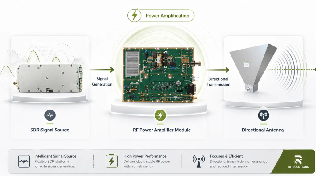
The SDR must provide the signal level and bandwidth required by the PA. The DC system must maintain the required voltage at the PA input terminals. The cooling structure must remove heat during the specified duty condition. The controller must configure and enable the correct channel. The feeder and antenna must then transfer the RF output without excessive loss or reflected power.
A system can therefore contain individually qualified components and still fail when the electrical, RF, thermal, mechanical, and control boundaries between them do not match.
Component Specifications vs Integration Boundaries
| What appears compatible | What may still be mismatched | What to verify | Possible result |
|---|---|---|---|
| SDR and PA cover the same frequency | Output level or waveform bandwidth | SDR output, path loss, PA input drive and bandwidth | The PA is underdriven or overdriven |
| PA reaches rated output | DC voltage, load, duty, or cooling condition | Loaded Vdc, Idc, duration and hot-state output | Output falls during extended operation |
| Antenna covers the required band | VSWR, power handling, gain, or pattern | Installed antenna-path data | Reflected power or unsuitable field coverage |
| Touchscreen enables a channel | Command state and actual PA state | Ready, alarm, enable and measured RF output | The interface shows ON without stable RF |
| One cabinet operates normally | Simultaneous full-load condition | All-channel DC, thermal and control test | Multiple channels fail when operated together |
| Components come from one engineering source | Project-specific interfaces still require verification | Interface matrix and integrated report | Unverified interfaces can delay troubleshooting |
Coordinated sourcing can reduce communication layers and make parameter changes easier to manage. Its real advantage is that frequency, power, control, cooling, RF routing, and acceptance responsibility can be reviewed within one engineering process.
A complete C-UAS RF PA selection should therefore include SDR drive, duty condition, 28V DC distribution, cooling, antenna path, protection, control, and test evidence—not only the PA model number.
2. How a Coordinated RF Core Reduces Interface Risk
A coordinated RF core brings several critical functions into one architecture:
- SDR signal generation and RF PA channels
- 28V DC power distribution
- Cooling and control hardware
- RF output and antenna interfaces
The integration advantage comes from reviewing these functions against one frequency plan, one power budget, one thermal boundary, one control sequence, and one acceptance plan.
The architecture should define:
- Which SDR output drives each PA channel
- Which frequency and gain setting belong to each channel
- Which channels may operate simultaneously
- How much DC current each operating mode requires
- How cabinet heat is removed
- Which feedback confirms PA readiness
- Which RF connector belongs to each antenna path
- Which test record is linked to the delivered cabinet
The SDR frequency range and RF PA operating band describe two different stages of the RF chain.
The SDR must generate the required signal. The selected PA must then provide the required gain and output power at the same frequency.
For example, an SDR may support signal generation across 100MHz to 6GHz, while the PA stage is selected from bands such as:
- 30–512MHz
- 300–1200MHz
- 300–1700MHz
- 300–2700MHz
- 2000–6000MHz
These ranges represent different RF PA module options. They should not be interpreted as one standard amplifier providing continuous full-power coverage across the complete SDR frequency range.
A rack-level RF core provides a practical platform for reviewing component layout, power distribution, airflow, control, RF routing, connector access, and operator interaction before the project configuration is frozen.
The coordinated engineering path can be summarized as:
Requirements lock → Interface definition → Component selection → Cabinet integration → System verification
This process turns separate RF components into an integration-ready system foundation.
3. Frequency Coverage Must Match End to End
System frequency coverage exists only where the SDR waveform, RF PA, feeder path, and antenna all meet the required frequency, bandwidth, power, and load conditions.
An SDR capable of generating a frequency does not prove that the PA reaches its target output there. A PA frequency range does not prove that the antenna has acceptable gain, VSWR, and power handling at the same point.
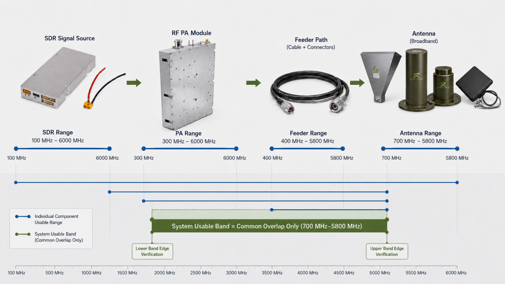
The usable system band is the range where all required stages meet their specifications at the same time.
The integration review should define:
- Required operating frequencies
- Band-edge points
- SDR output at each point
- Waveform and instantaneous bandwidth
- PA gain and target output
- Feeder and connector suitability
- Antenna frequency range
- Antenna power handling
- Antenna VSWR
- Radiation pattern
- Restricted frequency settings
- Future expansion points
The SDR signal source and the RF PA perform different functions. Broad SDR signal-generation capability must still be matched with a PA designed to deliver the required output in the selected operating band.
Why band edges require verification
A PA, feeder, connector, or antenna may behave differently near the edge of its specified range.
At a band edge:
- PA gain may change.
- Output flatness may become less favorable.
- Antenna VSWR may rise.
- Reflected-power margin may decrease.
- Feeder or connector loss may change.
- Protection may activate earlier.
Approval should therefore use the actual project frequencies and required band edges rather than one center-frequency result.
The practical rule is:
The usable system band is where every stage meets its requirement at the same time—not the widest frequency printed on one datasheet.
4. Match SDR Output to RF PA Input
The SDR-to-PA boundary is one of the most important interfaces in the RF chain.
The SDR must provide enough clean input drive for the PA to reach its target output without pushing the amplifier beyond its intended operating region.
Input drive means the RF signal level that actually arrives at the PA input.
It may differ from the SDR software setting because the source path can include:
- RF cables
- Connectors
- Attenuators
- Filters
- Switches
- Splitters
- Driver stages
- Internal cabinet routing
Each element can change the signal reaching the amplifier.
The interface review should define:
- SDR output-power range
- Source-path loss
- Actual PA input power
- Required PA input drive
- PA gain
- Gain-adjustment range
- Waveform bandwidth
- Supported PA bandwidth
- Startup output state
- Mute behavior during switching
- Overdrive margin
- Output-signal quality
If the input drive is too low, the PA may not reach the required output even though the amplifier is operating normally.
If the input drive is excessive, the PA can enter compression. Additional input then produces less proportional output and may increase current, heat, or unwanted signal content.
The correct drive level should be based on measured input-to-output behavior at the required frequencies.
A practical verification sequence is:
- Set the SDR to a defined frequency, waveform, and output condition.
- Measure or calculate the source-path correction.
- Confirm the RF level at the PA input reference plane.
- Record PA gain and output.
- Check Vdc and Idc.
- Verify thermal and protection status.
- Confirm the available drive margin.
The PA’s rated output alone cannot define this interface. Actual output depends on input drive, gain, frequency, DC condition, load, waveform, and thermal state.
In simple terms:
A weak signal may never drive the PA to target power. An excessive signal may push the PA beyond its intended operating boundary.
5. Power, Cooling, and Control Must Share One Worst Case
Reliable C-UAS RF component integration requires the DC, thermal, control, and RF boundaries to be verified under the same operating condition.
When RF output increases, the PA draws DC power and produces heat. When several channels operate together, their combined current affects the supply and distribution path.
The controller must coordinate startup, channel configuration, and RF enable within those same limits.
A cabinet is integration-ready only when its power distribution, cooling capacity, and control sequence support the same worst-case channel combination.
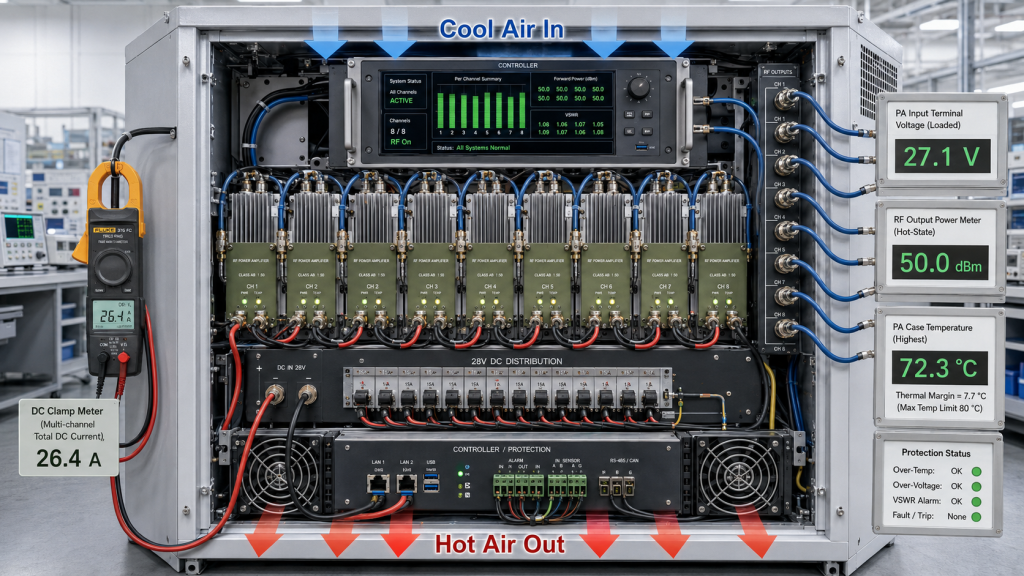
28V DC power distribution
The power review should define:
- Nominal operating voltage
- Permitted voltage range
- Continuous current per channel
- Simultaneous channel load
- Startup or transition current
- Cable and connector voltage drop
- Distribution-current rating
- Supply reserve
- SDR, controller, and fan consumption
The power supply should not be sized by adding RF output wattages.
RF output power is lower than the required DC input power because the PA is not 100% efficient. The supply must also support the SDR, controller, cooling fans, and distribution hardware.
DC acceptance should record the voltage at the PA input terminals under load, not only the voltage displayed at the power-supply output.
Cable, connector, and distribution losses may cause the PA input voltage to be lower than the supply output voltage.
Cooling
Cooling should be evaluated with the same active-channel combination used for DC sizing.
The review should connect:
- Total cabinet heat
- PA efficiency
- Module-to-heatsink contact
- External heatsink capacity
- Forced airflow
- Inlet and exhaust paths
- Hot-air recirculation
- Continuous-duty duration
- Hot-state RF output
A short cold-state test can confirm startup. Sustained operation must be confirmed after the system reaches its defined thermal condition.
The useful acceptance result is whether the cabinet maintains RF output, current, control, and protection status throughout the required operating duration.
Control
A typical control sequence may include:
Power available → Module addressed → Frequency and gain set → Protection checked → RF enabled → Ready confirmed → Output verified
The control system should distinguish between:
- A command being sent
- A command being accepted
- The module becoming ready
- RF output becoming stable
- The correct channel producing output
A touchscreen command confirms an operator request. Ready feedback and measured RF output confirm the actual module state.
Multi-channel systems should also define mute, timeout, alarm priority, protection recovery, and safe-state behavior. These boundaries are discussed further in multi-band RF PA control.
The practical rule is:
Power, cooling, and control must be approved against the same simultaneous-load and duty condition.
6. PA-Port Power Is Not Antenna-Input Power
The RF power measured at the PA or cabinet output connector is an important reference point. It is not automatically the available forward power at the antenna input.
The path may include:
- Cabinet feedthroughs
- RF connectors
- Adapters
- Switches or filters
- Lightning protection
- Feeder cable
- Antenna connectors
Each element may introduce insertion loss.
When logarithmic units are used:
Available forward power at the antenna input (dBm) = measured cabinet output power (dBm) − measured path insertion loss at the test frequency (dB)
When power is expressed in watts, the result must be calculated using linear transmission efficiency. A dB loss value must not be directly subtracted from a watt value.
Antenna mismatch should be evaluated separately through forward power, reflected power, return loss, or VSWR.
To calculate usable RF output power, correct forward and reflected power to the same reference plane, time, frequency scope, bandwidth, and power definition before calculating net accepted power.
The feeder and antenna may not maintain the same impedance match at every operating frequency. Part of the forward power may therefore be reflected toward the PA.
Depending on the module and protection settings, increased reflected power may produce:
- Higher current or heat
- Reduced forward output
- An alarm
- Protection foldback
- Temporary RF disable
Antenna-input power still does not describe the complete field result. Antenna gain and radiation pattern determine how RF energy is distributed in space.
Antenna gain does not create additional PA output power. It concentrates energy in selected directions.
The complete antenna-path review should define:
- PA-port output
- Cabinet connector output
- Path insertion loss
- Antenna-input forward power
- Reflected power
- Antenna frequency range
- Power handling
- Gain
- Radiation pattern
- VSWR
- Installation orientation
- Mounting condition
A dummy load establishes the PA baseline under a controlled load. The installed feeder and antenna path then confirms how the complete system behaves. This distinction is covered in dummy-load and real-antenna verification.
A useful report should keep the following reference points separate:
- PA output port
- Cabinet RF connector
- Feeder input
- Antenna input
- Forward power
- Reflected power
- Antenna-path VSWR
The customer-friendly distinction is:
“How much power leaves the cabinet?” and “How much forward power reaches the antenna input?” are different engineering questions.
When frequency response is the concern, antenna input power can fail even with flat RF PA gain because corrected Pout, path loss, mismatch, and hot-state behavior do not always change together.
Build the RFQ Around an Interface Matrix
An integration-ready RFQ should define every interface between the SDR, PA, power supply, controller, feeder, and antenna—not only the model number of each component.
The most useful starting document is a component interface matrix.
C-UAS RF Core Integration Matrix
| Interface | Project information to define | Acceptance evidence |
|---|---|---|
| SDR → RF PA | Frequency, output level, waveform bandwidth, path loss and mute behavior | SDR output and measured PA input |
| RF PA channel | Frequency points, input drive, gain, PA-port output, duty and protection limits | S/N-linked PA report |
| DC supply → Modules | Voltage, channel current, simultaneous load, voltage drop and reserve | Loaded Vdc and Idc at module terminals |
| Cooling → Cabinet | Heat load, heatsink, airflow, inlet condition and duration | Hot-state RF and temperature result |
| Controller → Modules | Addressing, frequency, gain, enable, ready, alarm and safe state | Command and status record |
| PA output → Antenna | Connector chain, insertion loss, power handling, gain, pattern and VSWR | FWD, REV, VSWR and antenna-input data |
| Cabinet → Delivery | Active channels, test duration, load, software version and configuration | Integrated S/N-linked report |
The RFQ should define:
- Target frequency points
- SDR output range
- Waveform and bandwidth
- Required PA input drive
- PA-port output target
- Number of PA channels
- Simultaneous operating combinations
- 28V supply condition
- Cooling method
- Cabinet size
- Control interface
- Ready and alarm logic
- Feeder length
- Antenna type
- Antenna-input target
- Duty condition
- Protection requirements
- Test duration
- Required reports
The key supplier questions are:
- What SDR level reaches each PA input?
- Which frequencies are verified end to end?
- What is the loaded voltage at each PA?
- What is the worst-case simultaneous DC load?
- How is cabinet heat removed?
- What feedback confirms PA readiness?
- What are the PA-port and antenna-input targets?
- Which protection states are recorded?
- Is the integrated report linked to the delivered cabinet S/N?
RF SKYPOWER applies this engineering approach across standard and custom RF PA projects with different bands, outputs, board layouts, connectors, control interfaces, and cooling structures.
Once the interface matrix is defined, the PA can be reviewed by frequency, input drive, output, 28V power, cooling, control, protection, and report format through the Custom RF Power Amplifier Modules engineering process.
Conclusion
Successful C-UAS RF component integration is not created by placing compatible-looking components inside the same cabinet. It is created by matching and verifying every interface under the same operating conditions.
The complete RF chain must connect:
SDR output → RF power amplifier input → PA output → Feeder path → Antenna
At the same time, the supporting system must align:
28V DC distribution → Cooling → Control → Protection → Acceptance evidence
RF SKYPOWER’s SDR signal sources, RF PA modules, antenna options, and cabinet-level integration hardware provide coordinated starting points for this architecture. The final configuration should then be confirmed through a defined interface matrix, one shared worst-case operating condition, and S/N-linked component and integrated test records.
For early engineering review, provide:
- Target frequency points
- SDR output level and bandwidth
- Required PA-port or antenna-input power
- Number of RF PA channels
- Simultaneous operating modes
- 28V DC supply conditions
- Cabinet dimensions
- Cooling method
- Control interface
- Feeder length and connector path
- Antenna type
- Duty condition
- Protection and acceptance requirements
RF SKYPOWER can review the RF power amplifier selection and complete RF-core interface boundary before the hardware configuration is frozen. The review can cover SDR-to-PA input matching, 28V DC power distribution, current reserve, cabinet cooling, multi-channel control, feeder loss, VSWR, antenna-input power, and S/N-linked acceptance evidence.
Define these boundaries before commissioning exposes insufficient drive, voltage drop, thermal limitations, incorrect channel control, or antenna-path mismatch.
Contact RF SKYPOWER to review your SDR, RF power amplifier, power supply, control, cooling, feeder, and antenna requirements before placing the RF core order.