











RF PA gain flatness can pass on paper while the installed system still develops one weak antenna input power point. The problem may not appear until the PA is connected to the real filter, switch, feeder, connectors, and antenna load—when the gain report still looks acceptable, but the delivered power no longer does.
That creates a more difficult question: does the weak frequency begin inside the PA, in the downstream RF path, at the antenna mismatch, or only after heat builds? The gain curve alone cannot answer it. Increasing the drive may even make the displayed output recover while hiding compression, voltage drop, reflected-power stress, or thermal rollback.
For standard or custom RF Power Amplifier Modules, approval should therefore not stop at a flat-looking curve. It should prove where the power changes between the measured PA input, the corrected PA output, the installed transmission path, and the antenna input reference plane.
The decisive step is to follow the power through those boundaries and identify which frequency loses margin first. That weak point is not always where the datasheet or module-level gain plot suggests.
1. What RF PA Gain Flatness Can—and Cannot—Prove
RF PA gain flatness describes how amplifier gain changes across a defined frequency range under stated test conditions.
Under a defined matched-load operating condition:
Large-signal power gain (dB) = Corrected forward Pout at the PA output reference plane (dBm) − Measured Pin at the PA input reference plane (dBm)
Pin and Pout must come from the same frequency, signal condition, load, DC boundary, thermal state, and measurement sequence.
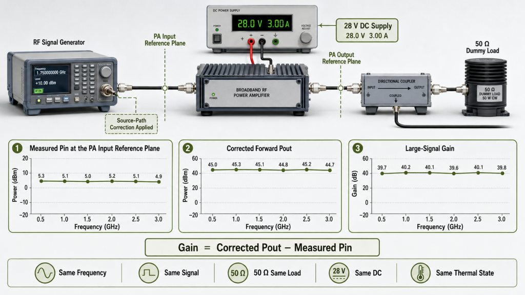
Small-signal flatness is not operating-power evidence
Datasheet gain flatness may be measured at a low input level or well below the intended output power.
It can describe the frequency-response shape, but it does not automatically prove:
- Large-signal output
- Output near compression
- Required backoff
- Modulated average power
- Multi-carrier composite power
- Hot-state output
- Antenna input power margin
The module-level procedure should first establish the required RF PA gain-flatness evidence. Downstream path loss should only be added after that baseline is clear.
Gain flatness is not output flatness
Gain depends on both Pin and Pout.
If measured Pin changes with frequency, an apparently flat gain curve may still produce uneven output. A PA may also show some gain variation while maintaining enough corrected Pout at every required point.
The approval record should therefore include:
- Measured large-signal power gain
- Corrected forward Pout at the PA output reference plane
A listed power class also does not replace evidence of usable RF output power under the approved signal, reference plane, DC, cooling, and load conditions.
Match the output metric to the signal
The required power quantity must be defined as one of the following:
- CW power
- Average power
- Composite average power
- Per-carrier average power
- Peak-envelope power
For modulated or multi-carrier operation, also define the waveform, occupied bandwidth, instantaneous bandwidth, carrier count, PAPR, backoff, compression boundary, and required linearity or spectral evidence.
A 47 dBm CW result is not interchangeable with 47 dBm composite average power under a high-PAPR waveform.
What Each Measurement Boundary Can Prove
| Boundary or metric | What it proves | What it does not prove |
|---|---|---|
| Small-signal gain flatness | Frequency-response shape under the stated low-drive condition | Large-signal output or hot-state margin |
| Large-signal power gain | Gain at the defined operating point | Downstream RF-path performance |
| Corrected forward Pout at the PA output | Output at the approved PA reference plane | Power reaching the antenna input |
| Downstream insertion loss | Transmission loss between defined reference planes | Antenna mismatch or PA protection behavior |
| Forward power at the antenna input | Incident power reaching the antenna plane | Net power accepted by a mismatched antenna |
| Net accepted power | Forward power minus reflected power in compatible linear units | Radiation pattern or field coverage |
| Field evidence | Result under the approved installation and propagation conditions | The RF-chain cause of a weak point |
2. How to Calculate Forward Power at the Antenna Input
Under a defined transmission-path condition:
Forward power at the antenna input (dBm) = Corrected forward Pout at the PA output reference plane (dBm) − Verified downstream insertion loss (dB)
The downstream path may include:
- PA output cable
- Filter
- RF switch
- Directional coupler
- Surge protection
- Adapters and connectors
- Feeder
- Antenna-side connector
Use frequency-specific loss values for the approved path. Remote installations should define the complete installed RF path loss before the PA output class or antenna-plane margin is approved.
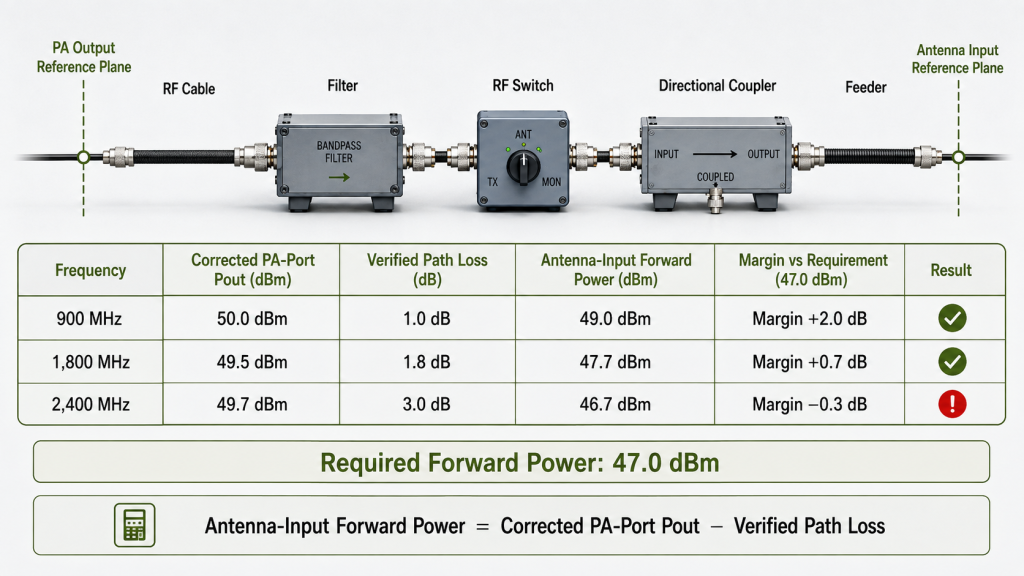
Apply the formula only under compatible conditions
The PA-port result and path-loss data must use compatible:
- Reference planes
- Impedance conditions
- Frequencies
- Signal states
- Power-reporting bases
- Thermal conditions
Low-power S-parameter data can establish an initial insertion-loss baseline. It does not automatically prove high-power or hot-state loss.
Filters, switches, couplers, surge protectors, connectors, and feeders may change with RF power, duty cycle, temperature, contact condition, or component heating. Where these effects are material, verify the path under representative power, duty, temperature, and operating duration.
Under a materially mismatched antenna load, ordinary matched-path insertion loss may not represent the complete source-load interaction. Direct forward and reflected measurements at the antenna plane, or an approved de-embedding method, may be required.
Calculate forward-power margin
When acceptance is based on forward power:
Forward-power margin (dB) = Forward power at the antenna input (dBm) − Required forward power (dBm)
A positive calculated margin does not automatically establish a pass. Measurement uncertainty and the agreed decision rule must still be applied.
Example: the lowest PA output may not be the weakest installed point
The example below assumes the same measured Pin, power-reporting basis, reference planes, DC condition, thermal state, and no active protection limiting.
| Frequency | Corrected PA-port forward Pout | Verified path loss | Forward power at antenna input | Required forward power | Calculated margin |
|---|---|---|---|---|---|
| 900 MHz | 50.0 dBm | 1.0 dB | 49.0 dBm | 47.0 dBm | +2.0 dB |
| 1,800 MHz | 49.5 dBm | 1.8 dB | 47.7 dBm | 47.0 dBm | +0.7 dB |
| 2,400 MHz | 49.7 dBm | 3.0 dB | 46.7 dBm | 47.0 dBm | −0.3 dB |
The lowest PA-port output occurs at 1,800 MHz. The installed failure occurs at 2,400 MHz because the downstream loss is higher there.
A gain curve alone would not identify the final weak point.
A fixed loss applied equally at every frequency lowers every result by the same amount. Frequency-dependent loss changes the relative margin and can deepen a weak point when its highest loss overlaps with lower PA output.
3. How to Separate Path Loss from Antenna Mismatch
Transmission loss and antenna mismatch are different conditions.
Filters, cables, connectors, switches, and couplers create insertion loss between reference planes.
Antenna mismatch may change:
- Reflected power
- VSWR
- Standing-wave distribution
- PA output behavior
- Current
- Temperature
- Protection response
Do not convert VSWR into an arbitrary path-loss number and subtract it from PA output.
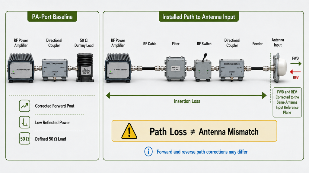
Use two verification stages
Stage 1: PA-port baseline
Test the PA against a suitable defined load, normally 50 Ω.
At each required frequency, record:
- Measured Pin
- Corrected forward Pout
- Large-signal power gain
- Waveform and power-reporting basis
- PA-terminal voltage and current
- Temperature and operating duration
- Forward and reflected power
- VSWR
- Control and protection status
This determines whether the weak point already exists at the PA output.
A fixed-Pin comparison requires the same measured Pin at the PA input reference plane. The same SDR or generator setting is not enough because the source path may have frequency-dependent loss.
If Pin is adjusted to force the target Pout, record the required Pin, compression margin, backoff, and spectral result. Do not report it as a fixed-Pin gain-flatness curve.
Stage 2: Installed path and load
After the module baseline is understood, verify:
- Frequency-dependent insertion loss
- High-power or hot-state path behavior where required
- Forward power at the antenna input
- Reflected power at the same reference plane
- VSWR or return loss
- PA protection response
- Net accepted power where required
Separate dummy-load and real-antenna checks prevent module performance, path loss, and antenna behavior from being combined into one unclear result.
Correct FWD and REV to the same reference plane
Net accepted power can only be calculated after forward and reflected power have been corrected to the same antenna input reference plane.
When the directional coupler is upstream, account for:
- Forward and reverse coupler factors
- Forward- and reverse-path corrections
- Frequency response
- Coupler directivity
- FWD/REV channel isolation
- Attenuator and sensor uncertainty
- Cable and connector repeatability
The reflected signal travels from the antenna toward the coupler. Its correction is not automatically identical to the forward-path correction.
Calculate net accepted power in linear units
When net accepted power is required:
Net accepted power (W) = Forward power (W) − Reflected power (W)
Do not subtract two dBm values.
For measurements recorded in dBm:
Power (mW) = 10^(Power in dBm / 10)
Convert forward and reflected values to milliwatts, subtract them, and then convert the result back to dBm where required.
The RFQ must state whether acceptance is based on forward power, reflected power, VSWR, net accepted power, or a combination of these limits.
Observed Weak Point, Likely Boundary, and Next Action
| Observed result | Likely boundary | Next action |
|---|---|---|
| Fixed-Pin PA-port Pout is low | PA gain, compression, DC, thermal, or module condition | Recheck the module baseline |
| PA-port output passes but antenna-plane forward power is low | Downstream component or feeder loss | Verify insertion loss by frequency and operating state |
| Forward power reaches the antenna plane but reflected power is high | Antenna match, feeder, connector, or installation | Correct the load boundary and repeat FWD/REV measurements |
| Cold-state result passes but hot-state output falls | Cooling, voltage drop, thermal rollback, or hot path behavior | Repeat after thermal stabilization |
| Target output requires increased Pin | Drive margin may be limited | Record required Pin, compression margin, backoff, and spectral result |
| Gain is uneven but final margin passes | RF chain may still be acceptable | Judge against the approved limit, not curve appearance |
| PA and RF path pass but field performance is weak | Antenna pattern, orientation, interference, or propagation | Move to project-defined field verification |
Do not correct a downstream loss or mismatch problem by increasing PA drive. This may increase current, heat, compression, distortion, reflected-power stress, or protection activity without correcting the original fault.
4. Which Frequencies Require Full-Chain Verification?
Full-chain verification should focus on frequencies most likely to lose installed margin:
- Required operating points
- Priority frequencies
- Band edges
- Filter or switch transition points
- Frequencies with higher measured path loss
- Frequencies with known antenna-match changes
- Verified local PA-output dips
- Frequencies requiring higher Pin
- Frequencies with reduced hot-state margin
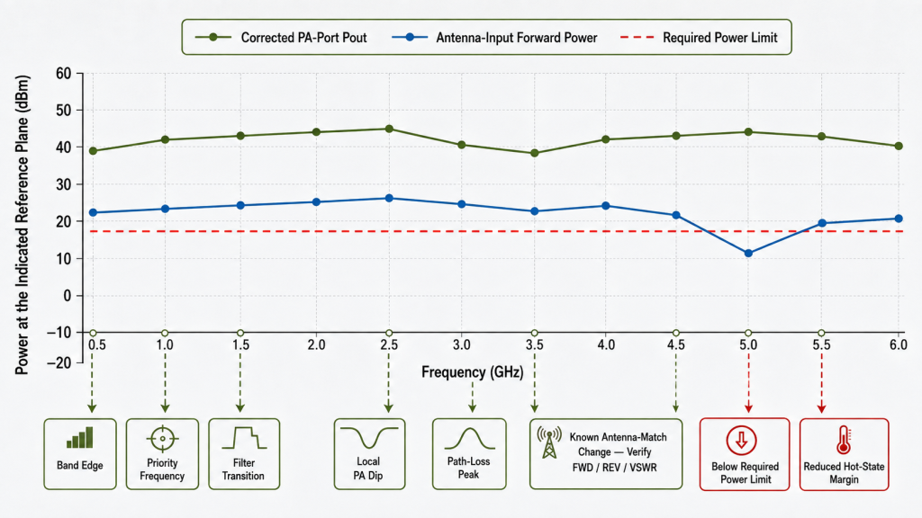
Do not assume that only the lowest, center, and highest points are sufficient.
Where a required frequency is close to its limit, add enough adjacent points to distinguish a broad PA trend, local output dip, filter transition, path-loss peak, mismatch change, or measurement artifact.
Use verified ripple and hot-state results as inputs to the full-chain review. Do not replace their dedicated test procedures with a simple three-point calculation.
5. What Evidence Proves the Final Result?
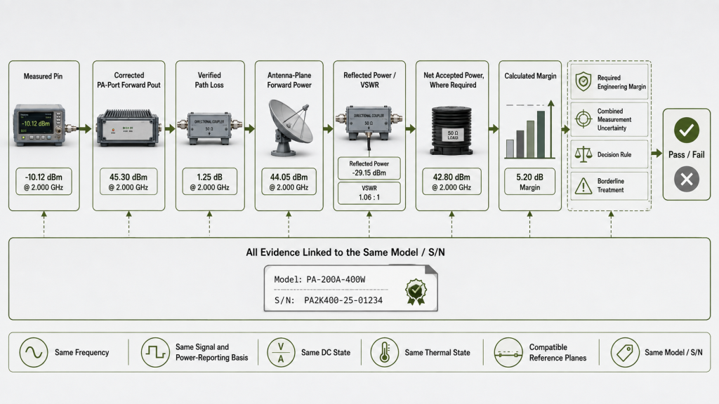
The final evidence should connect:
- Corrected PA-port forward Pout
- Verified downstream insertion loss
- Forward power at the antenna input
- Reflected power or VSWR at the same reference plane
- Net accepted power where required
- Required output and engineering margin
- Combined measurement uncertainty
- Acceptance decision rule
- Final pass/fail conclusion
- Model and S/N linkage
The evidence chain should follow one direction:
Measured Pin → Corrected PA-port forward Pout → Verified path loss → Antenna-plane forward power → Load result → Final margin → Pass/fail
Do not combine:
- Pin and Pout from different setups
- Room-temperature output with hot-state path data
- CW output with a modulated average-power requirement
- Low-power path loss with an unqualified high-power claim
- Forward and reflected power from different reference planes
- Unit-level evidence from different serial numbers
- Fixed-Pin and adjusted-Pin results without identifying the change
- Matched-load insertion loss as proof of acceptable antenna mismatch
Apply uncertainty before declaring a pass
The uncertainty budget may include:
- Pin and Pout measurement
- Coupler factor and directivity
- FWD/REV isolation
- Attenuator and sensor accuracy
- Cable and connector correction
- Path-loss measurement
- Reference-plane de-embedding
- Temperature repeatability
- Rounding
A calculated margin of +0.2 dB is not a clear pass when the unresolved uncertainty is larger than that margin.
The acceptance method should define:
- Required engineering margin
- Combined measurement uncertainty
- Guard band where used
- Repeat-test requirement
- Rounding method
- Treatment of borderline results
- Final pass/fail rule
RFQ: What Must Be Defined Before Antenna-Input Power Is Approved?
| RFQ field | What to specify |
|---|---|
| Frequency plan | Required points, priority frequencies, band edges, and critical transitions |
| Waveform and power basis | CW, pulsed, or modulated waveform; average, composite average, per-carrier average, or peak-envelope power |
| Carrier and bandwidth state | Carrier count, spacing, simultaneous operation, occupied bandwidth, instantaneous bandwidth, PAPR, and backoff |
| PA input boundary | Pin reference plane, fixed- or adjusted-Pin method, maximum Pin, and source-path correction |
| PA output boundary | Corrected forward Pout reference plane and required module-level output |
| Downstream RF path | Filters, switches, couplers, surge devices, connectors, adapters, and feeder |
| Path-loss evidence | Frequency-specific method, power level, thermal state, and correction boundary |
| Antenna input boundary | Exact forward and reflected power reference plane |
| Power and mismatch limits | Required forward power, maximum reflected power, VSWR or return-loss limit, and net accepted power where used |
| DC and thermal boundary | PA-terminal voltage, current capacity, cooling, ambient, duty, and stabilization period |
| Control and protection | Gain, attenuation, enable, limiting, rollback, alarm, and reset state |
| Engineering margin | Required margin above the approved power or mismatch limit |
| Uncertainty and decision rule | Combined uncertainty, guard band, repeat test, rounding, and borderline-result treatment |
| Evidence and responsibility | Model/S/N linkage, required report, and supplier/integrator/installer responsibility |
Conditions that remain unknown should stay as open engineering questions. They should not become undocumented quotation assumptions.
Conclusion
RF PA gain flatness alone cannot prove antenna input power.
The review must begin with measured Pin and corrected forward Pout under the approved signal, DC, load, and thermal conditions. Frequency-specific path loss can then be applied only when its reference planes and operating conditions are compatible with the PA result.
Antenna mismatch requires separate forward, reflected, VSWR, protection, and net accepted power evidence at the same antenna input reference plane.
RF SKYPOWER can review how PA operating gain, corrected output, installed path loss, and antenna-load behavior combine at the required frequencies. Submit the completed RF and acceptance conditions through the RF SKYPOWER contact page to determine whether the weakest point begins inside the PA, in the transmission path, or at the antenna load boundary before a standard or custom configuration is approved.