










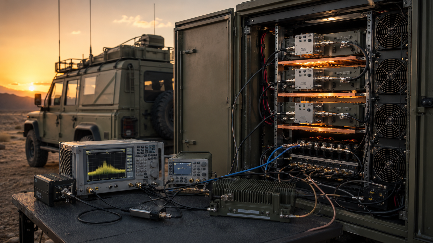
An RF PA can pass every cold gain point and still lose its required output after thermal stabilization. The failure may appear at only one priority frequency—after the module has already passed inspection, entered integration, or been accepted for the next project stage.
The obvious conclusion is that heat changed the PA. But that conclusion may be wrong.
The same hot-state gain drop can be created by lower input drive, PA-terminal voltage loss, a changing load, protection back-off, compression movement, or even a test cable or coupler that heated during the measurement. Increasing Pin may make the output recover, while quietly reducing backoff and hiding the original problem.
That leaves one question the cold sweep cannot answer: where does the hot-state loss actually begin?
For standard or custom RF Power Amplifier Modules, acceptance should not stop at comparing two gain numbers. It should prove whether the change begins inside the PA, before the PA input reference plane, in the DC path, at the load boundary, or inside the measurement chain.
The weakest stabilized frequency is not always the weakest cold gain point—and the first apparent fix is not always the correct one.
1. When Are the Cold and Hot Gain States Valid?
A cold result and a hot result are only useful when both operating states are defined.
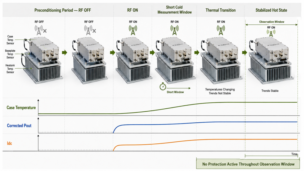
Define the cold baseline
“Cold” should not mean a random first reading after startup.
The cold baseline should record:
- Ambient or chamber-air temperature
- PA case or baseplate temperature
- Heatsink temperature where required
- Preconditioning time
- RF-off or RF-on starting state
- Time between RF turn-on and the cold measurement
- Measured Pin
- PA-terminal voltage
- Load and cooling condition
The cold baseline is not automatically a low-temperature environmental test. It is the approved starting condition used for comparison with the stabilized operating state.
A repeatable cold baseline might begin after the unit has remained RF-off at a defined ambient temperature for a specified period. The first measurement must then be completed inside an agreed time window after RF is applied.
Without that definition, one technician may record the result within seconds while another waits several minutes. Both may call the result “cold,” even though the PA has reached different temperatures.
Identify each temperature by its physical point
Do not report one generic “PA temperature” when several temperatures are involved.
The record should distinguish:
- Chamber-air temperature
- Cabinet-air temperature
- PA case temperature
- Baseplate temperature
- Heatsink temperature
- Thermal-interface temperature where measured
- Estimated junction temperature where supported
These values are not interchangeable.
A chamber can reach its programmed temperature before the PA reaches thermal equilibrium. A stable heatsink temperature also does not directly prove a stable semiconductor junction temperature.
If junction temperature is estimated rather than measured, identify the thermal model, sensor input, assumptions, and calculation method. Do not present an estimated junction temperature as a direct measurement.
Define thermal stabilization by trends, not time alone
Thermal stabilization is not simply “30 minutes after power-on.”
The project should define which indicators must remain inside approved change limits throughout an observation window.
A stabilization rule may use:
|ΔTemperature| ≤ approved temperature-change limit

and

|ΔCorrected Pout| ≤ approved output-change limit

and/or

|ΔIdc| ≤ approved current-change limit

throughout the defined observation period,
with no active limiting or protection state.
The exact limits and observation period should match the project. A compact 30 W module on an open bench and a 200 W module in a restricted cabinet should not automatically use the same stabilization time.
Useful stabilization indicators include:
- Case or baseplate temperature
- Corrected forward Pout
- Large-signal gain
- Idc
- PA-terminal voltage
- Forward and reflected power
- Protection status
Do not declare stabilization only because Pout has stopped changing while thermal rollback, current limiting, or reflected-power protection remains active. A protection-limited plateau is not unrestricted hot-state operation.
A broader thermal-soak power test may be required when the project must also verify hot-state output, current, efficiency, protection margin, and continuous operating duration.
Long-duration movement that continues after the approved stabilization point belongs to a separate RF PA gain-drift review.
2. What Must Stay Fixed Between Cold and Hot Measurements?
Under a defined operating condition:
Large-signal power gain (dB) = Corrected forward Pout at the PA output reference plane (dBm) − Measured Pin at the PA input reference plane (dBm)
Cold and hot gain values are comparable only when the measurement boundaries are compatible.
Keep the following conditions fixed or explicitly controlled:
- PA input reference plane
- PA output reference plane
- Measured Pin
- Frequency
- Waveform
- Power-reporting basis
- Load
- Cooling boundary
- PA-terminal voltage
- Operating duty
- Measurement correction
- Instrument configuration
If one of these conditions changes, the measured difference may contain more than PA thermal behavior.
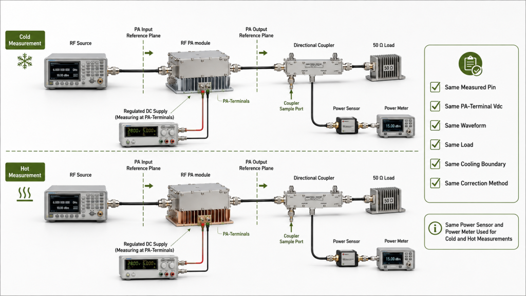
Separate controlled module testing from installed-system testing
These two tests answer different questions.
Controlled module test
Use this test to isolate PA thermal behavior.
Hold constant:
- Measured Pin
- PA-terminal voltage
- Defined matched load
- Cooling boundary
- Frequency points
- Waveform
- Output reference plane
- Measurement corrections
The result shows how the PA behaves from the approved cold baseline to the stabilized operating state under controlled conditions.
Installed-system test
Use this test to verify real deployment behavior.
Retain the actual:
- DC cable and connectors
- Power distribution path
- Filter
- RF switch
- Coupler
- Feeder
- Antenna or installed load
- Cabinet cooling condition
Then record voltage drop, path loss, mismatch, protection response, and final output separately.
Do not call an installed-system power reduction a module hot-state gain failure until the source of the change has been isolated.
Measure Pin at the PA input reference plane
The same generator or SDR setting does not prove that the same Pin reaches the PA.
Input cables, switches, attenuators, connectors, and driver amplifiers can change with frequency, temperature, or operating time.
Measure or correct Pin at the approved PA input reference plane at every required frequency.
If Pin falls after the source path heats, Pout may fall while calculated gain appears nearly unchanged. If Pin increases, the output may appear to recover while the PA moves closer to compression.
Correct Pout to one approved reference plane
Cold and hot Pout must use the same output reference plane and correction method.
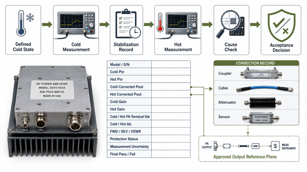
The correction record may include:
- Directional-coupler factor
- Coupler directivity
- Cable loss
- Connector loss
- Attenuator value
- Sensor calibration
- Frequency-response correction
- Instrument uncertainty
Do not compare cold corrected PA-port output with a hot reading taken after a filter, switch, feeder, or antenna path.
Keep the waveform and power basis consistent
A CW gain result is not directly interchangeable with gain calculated from modulated average power or multi-carrier composite power.
For modulated or simultaneous operation, define:
- Waveform or signal family
- Occupied bandwidth
- Instantaneous bandwidth
- Carrier count and spacing
- PAPR or crest factor
- Required output backoff
- Average, composite, per-carrier, or peak-envelope power basis
The same reporting basis must be used in both states.
Record operating backoff and compression boundary
A fixed-Pin comparison near compression may contain two effects:
- Thermal movement in the PA
- A change in compression margin
Record the approved operating backoff or compression boundary.
Where the PA operates near compression, report hot-state gain together with:
- Corrected Pout
- Required output backoff
- Compression margin
- Linearity or spectral evidence where required
A small-signal hot-state sweep can show movement in the response shape. It does not replace large-signal gain and corrected Pout at the intended operating point.
When the test boundaries are compatible:
Hot-state gain change (dB) = Stabilized large-signal gain (dB) − Cold large-signal gain (dB)
A negative result shows that measured gain decreased. It does not independently establish a failure.
3. Which Frequencies Require Hot-State Gain Verification?
One center-frequency result cannot prove hot-state performance across a wide operating range.
The verification plan should include frequencies with the highest project risk:
- Required operating points
- Priority frequencies
- Approved band edges
- Known cold-state gain dips
- Frequencies close to the minimum Pout limit
- Frequencies requiring higher Pin
- High-current operating points
- Lower-efficiency points
- Filter or switch transitions
- Frequencies that previously activated protection
Low, center, and high points may provide an initial sweep, but they are not automatically sufficient.
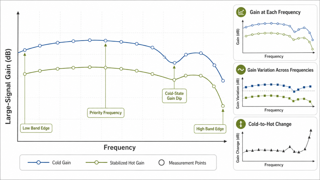
Use the same points for cold and hot comparison
A cold sweep at one set of frequencies and a hot sweep at another cannot establish point-by-point thermal change.
At every compared frequency, retain the same:
- Measured Pin
- Waveform
- Power-reporting basis
- Load condition
- PA-terminal voltage requirement
- Output correction
- Stabilization rule
This reveals whether the hot-state weak point already existed in the cold result or appeared only after stabilization.
Keep three results separate
Do not combine the following into one “gain flatness” conclusion:
- Gain at each required frequency
- Maximum gain variation across the approved frequencies
- Cold-to-hot gain change at each frequency
A PA may preserve the same gain shape while every point decreases by 0.8 dB. It may also remain stable at most frequencies while one band edge loses 1.2 dB.
Those are different engineering results.
The frequency sweep should first establish valid RF PA gain-flatness evidence. The hot-state comparison should then show how each approved point changes after stabilization.
Separate module gain from installed-path behavior
Use a defined matched-load test to judge module hot-state gain.
Report the effects of filters, switches, feeders, connectors, or antenna loads as installed-path behavior rather than combining them into the module gain result.
A module test may record:
- Measured Pin
- Corrected PA-port Pout
- Large-signal gain
- PA-terminal Vdc
- Idc
- Temperature
An installed-path test may additionally record:
- Path loss
- Antenna-plane forward power
- Reflected power
- VSWR
- Protection response
The weakest module-gain point and the weakest installed-output point may not be the same.
4. How to Identify the Real Cause of a Hot-State Change
A hot-state gain result should be reviewed with Pin, Pout, voltage, current, temperature, load, measurement-chain condition, and protection status.
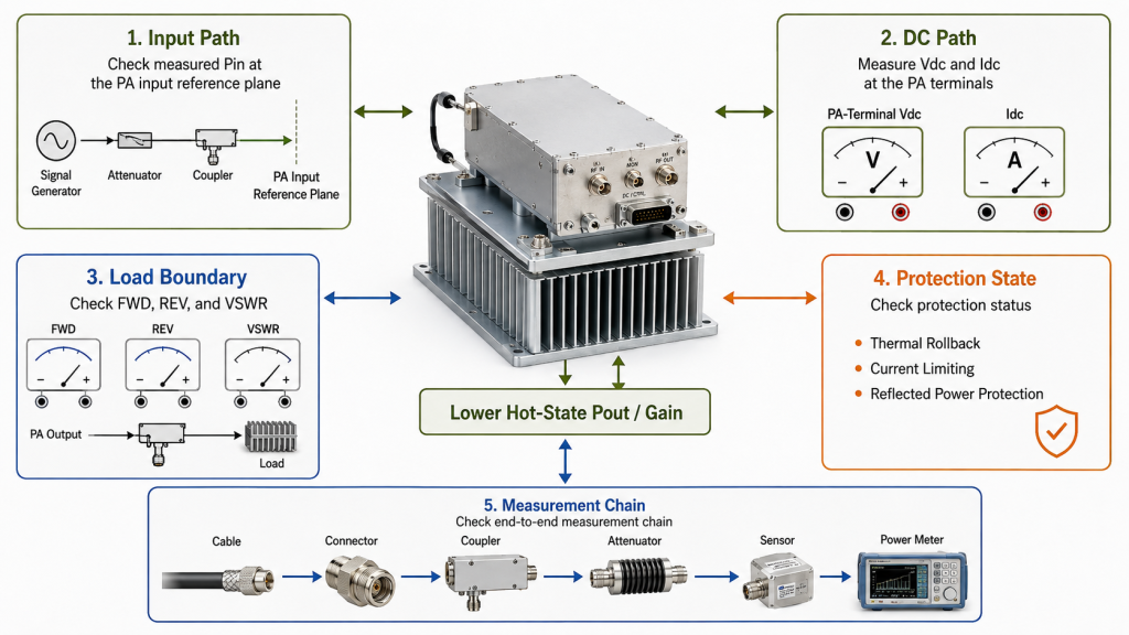
| Observed result | Possible cause | Evidence needed | Acceptance action |
|---|---|---|---|
| Pin remains stable while gain and Pout decrease | PA thermal behavior, bias movement, compression change, or cooling limit | Temperature, Idc, corrected Pout, repeated hot sweep | Judge against approved hot-state limits |
| Pin decreases after warm-up | Driver, cable, switch, connector, or source-path drift | Pin at the PA input reference plane | Correct the source condition and repeat |
| PA-terminal voltage falls under RF load | Supply limit, DC cable loss, connector heating, or current limit | Vdc and Idc measured at the PA terminals | Correct the DC path before judging the PA |
| REV or VSWR increases as temperature rises | Load, feeder, connector, filter, or antenna change | FWD, REV, VSWR, and load configuration | Correct the load boundary and repeat |
| Protection becomes active | Thermal limit, reflected power, overcurrent, or control condition | Alarm log, temperature, current, FWD, REV | Do not report as unrestricted hot-state gain |
| Gain remains similar while Pout falls | Pin may have fallen by a similar amount | Measured Pin and corrected Pout | Do not approve from gain alone |
| Gain changes while Pout still passes | Permitted gain movement may remain acceptable | Gain window, Pout limit, uncertainty | Apply the approved decision rule |
| Results shift without matching PA, DC, or load changes | Measurement-chain drift | Cable, coupler, attenuator, sensor, and correction checks | Bound or correct measurement drift |
Check voltage at the PA terminals
Supply voltage should be measured under RF load at the PA-terminal reference point, not only at the power-supply display.
For a 28 V PA system, voltage may be lost through:
- DC cable resistance
- Connectors
- Relays
- Fuses
- Current-monitoring devices
- Distribution hardware
A hot DC path can reduce Pout, gain, and compression margin. That result should not automatically be assigned to the RF transistor or matching network.
Keep load behavior separate
A defined 50 Ω load establishes the module baseline.
An installed feeder or antenna path may introduce:
- Higher reflected power
- Frequency-dependent mismatch
- Connector heating
- Filter drift
- Protection activity
Record forward power, reflected power, VSWR or return loss, load configuration, and protection state.
Do not convert VSWR into an arbitrary gain correction.
Check whether the measurement chain also heats
Part of the apparent change may come from the test setup.
Confirm whether any cable, coupler, attenuator, connector, or sensor is exposed to:
- Chamber temperature
- Cabinet heat
- High RF power
- Long operating duration
Where correction values may change, verify or bound:
- Cable-loss drift
- Coupler-factor drift
- Coupler directivity
- Attenuator heating
- Sensor zero or calibration drift
- Connector reconnection repeatability
Do not assign the full measured difference to the PA until the measurement-chain contribution is understood.
Do not hide the result by increasing Pin
Increasing Pin may restore displayed Pout, but it can reduce backoff and increase:
- Current
- Heat
- Compression
- Distortion
- Spectral regrowth
- Protection stress
If Pin is adjusted, report:
- Original measured Pin
- Adjusted measured Pin
- Achieved corrected Pout
- Resulting gain
- Compression or backoff margin
- Required spectral result
An adjusted-Pin test is not a fixed-Pin cold-to-hot comparison.
5. What Evidence Proves Hot-State Gain Acceptance?
The final report should prove ten core items:
- Unit identity
Model, serial number, hardware revision, report number, and test date - Cold starting condition
Ambient, approved temperature points, preconditioning, RF state, and measurement timing - Stabilization criterion
Indicators, allowed change limits, observation period, and protection status - Cold and hot Pin
Measured at the same PA input reference plane - Cold and hot corrected Pout
Corrected to the same PA output reference plane - Cold and hot large-signal gain
Calculated from compatible Pin and Pout data - Operating state
PA-terminal Vdc, Idc, duty, waveform, cooling, load, and approved temperature points - Load and protection evidence
FWD, REV, VSWR or return loss, alarms, limiting, and rollback state - Measurement quality
Correction record, uncertainty, repeatability, and measurement-chain thermal effects - Final decision
Applied limits, guard band, borderline treatment, and pass/fail conclusion
The evidence chain should remain continuous:
Defined Cold State → Cold Measurement → Stabilization Record → Hot Measurement → Cause Check → Acceptance Decision
Use one S/N throughout
Do not combine:
- Cold data from one unit with hot data from another
- Pin from one setup with Pout from another
- Small-signal gain with full-power Pout
- CW data with a modulated requirement
- Matched-load gain with installed-path loss without identifying the boundary
- Room-temperature corrections with an unverified heated measurement path
Apply uncertainty before declaring a pass
The uncertainty budget may include:
- Pin measurement
- Output-sensor accuracy
- Coupler factor and directivity
- Cable and connector correction
- Attenuator tolerance
- Frequency-response correction
- Sensor drift
- Thermal drift of the measurement path
- Temperature repeatability
- Reference-plane de-embedding
- Reported-value rounding
A measured cold-to-hot change of −0.3 dB does not establish failure when the unresolved uncertainty is similar or larger.
The decision rule should define:
- Minimum hot-state gain
- Maximum cold-to-hot gain change
- Minimum corrected Pout
- Required output backoff
- Measurement uncertainty
- Guard band where used
- Repeat-test requirement
- Rounding method
- Borderline-result treatment
- Final pass/fail method
A broader swept-frequency full-power RF PA test can provide the surrounding output, current, load, frequency-response, and protection evidence when gain acceptance alone is insufficient.
RFQ: What Must Define Hot-State Gain Acceptance?
| RFQ field | What to specify |
|---|---|
| Frequency plan | Required points, priority frequencies, band edges, and critical transitions |
| Waveform and power basis | CW, pulsed, or modulated signal; average, composite, per-carrier, or peak-envelope power |
| Operating point | Required Pin, corrected Pout, output backoff, and compression boundary |
| Cold baseline | Ambient, case or baseplate temperature, preconditioning, RF state, and timing |
| Stabilization rule | Temperature, Pout, gain, or Idc change limit and observation period |
| Temperature points | Chamber, cabinet, case, baseplate, heatsink, or supported junction estimate |
| Measurement boundaries | PA input and output reference planes and correction method |
| Controlled module test | Fixed Pin, PA-terminal Vdc, matched load, cooling, and frequency points |
| Installed-system test | Actual DC path, RF path, load, cabinet, and antenna conditions |
| DC condition | PA-terminal voltage, current capacity, cable path, and permitted voltage drop |
| Load boundary | Defined load, maximum reflected power, VSWR, or return-loss limit |
| Protection state | Permitted alarms, rollback, current limiting, and reflected-power response |
| Acceptance limits | Minimum gain, maximum thermal change, minimum Pout, and required margin |
| Measurement quality | Uncertainty, guard band, repeatability, rounding, and borderline treatment |
| Evidence scope | Model/S/N linkage, sample or unit-level evidence, and report format |
Unknown conditions should remain open engineering questions. They should not become undocumented quotation assumptions.
Conclusion
Cold gain proves only a defined starting state. Hot-state gain becomes valid only after the PA reaches an approved stabilization condition and the cold and hot measurements use compatible Pin, Pout, waveform, load, voltage, cooling, operating point, reference planes, and corrections.
A lower hot-state result does not automatically prove module failure. Input-path drift, DC voltage loss, mismatch, protection activity, compression movement, or measurement-chain heating may create the same apparent change.
Acceptance should therefore connect hot-state gain with corrected Pout, temperature, current, load behavior, measurement uncertainty, repeatability, and a defined decision rule.
RF SKYPOWER can review hot-state gain requirements before quotation. Submit the target frequencies, waveform, measured Pin, required Pout, output backoff, PA-terminal voltage, duty cycle, cooling, temperature points, load or VSWR boundary, stabilization criterion, gain tolerance, and required report format through the RF SKYPOWER contact page.