










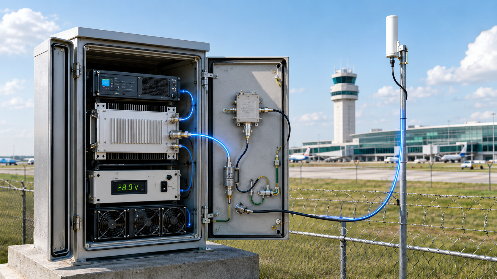
Feeder loss can make antenna-input power fall below the project requirement even when an RF power amplifier passes its module-level gain test. That does not automatically mean the amplifier gain is too low; the installed RF path may be removing power after the PA output reference plane.
That does not automatically mean the feeder reduced the amplifier’s gain.
The first question is where the input and output powers were measured. Module gain compares actual Pin at the PA input reference plane with corrected Pout at the PA output reference plane. Loss after the PA output plane reduces downstream forward power and end-to-end gain, but it should not be reported as lower module gain unless the PA operating condition also changes.
This distinction becomes important when the installed RF path includes feeder cable, connectors, cabinet feedthroughs, lightning protection, filters, or RF switches. Frequency-dependent insertion loss can make an antenna-input power curve look like PA gain roll-off. A mismatched antenna path can also change reflected power, PA-port output, current, temperature, or protection behavior.
Before an RF Power Amplifier Module is rejected, resized, or driven harder, the approval record must separate four results:
- Module gain
- Downstream path loss
- Antenna-input forward power
- PA behavior under the real installed load
1. What Does RF Power Amplifier Gain Measure?
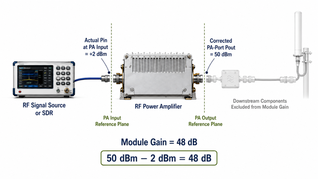
Module-level RF power amplifier gain describes the increase in RF power between the approved PA input and output reference planes.
For large-signal gain:
Module gain (dB) = Corrected PA-port Pout (dBm) − Measured PA-input Pin (dBm)
If actual Pin at the PA input connector is +2 dBm and corrected Pout at the PA output connector is 50 dBm:
Module gain = 50 dBm − 2 dBm = 48 dB
The 48 dB result describes the amplifier itself. It does not include components installed after the PA output reference plane.
A gain result should therefore identify:
- Test frequency or frequency points
- Actual Pin at the PA input
- Corrected Pout at the PA output
- Input and output reference planes
- Signal or waveform condition
- DC voltage
- Load condition
- Cooling condition
- Thermal state
- Operating duration
“Input power” and “output power” are not sufficient labels. Output power might refer to the PA connector, cabinet output, feeder end, antenna input, or another approved system boundary.
A 50 dBm reading at the PA output and a 47 dBm reading at the antenna input can both be correct. They describe different reference planes.
The same boundary discipline is required when comparing small-signal and large-signal RF PA gain. A catalog gain value, a small-signal analyzer trace, and a full-power operating result should not be treated as interchangeable evidence.
2. What Does Feeder Loss Actually Change?
Consider this RF chain:
SDR or Signal Source → RF PA → Filter or Switch → Feeder Cable → Antenna
When module gain is measured between the PA input and PA output connectors, everything after the PA output is outside the module-gain calculation.
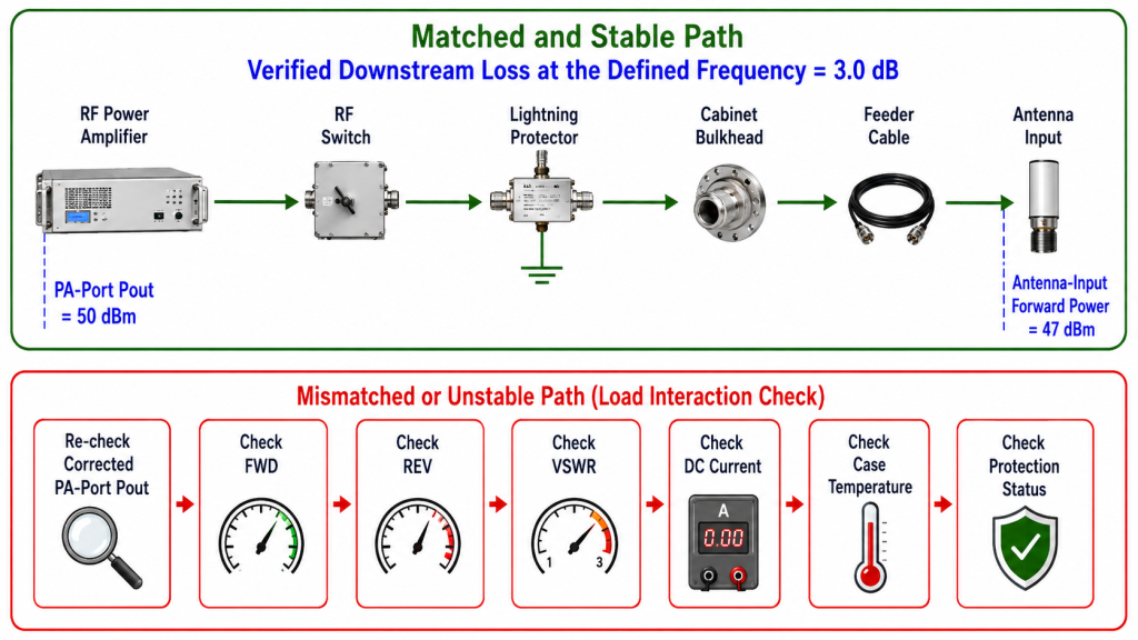
The downstream path may include:
- RF switches
- Filters
- Lightning protectors
- Cabinet bulkheads
- Connectors and adapters
- Feeder cable
- Antenna-side jumpers
These components can reduce the forward power that reaches the antenna input.
Under a matched and stable operating condition, feeder insertion loss reduces delivered power and end-to-end gain while the measured module gain remains unchanged.
For example:
- PA-input Pin: +2 dBm
- Corrected PA-port Pout: 50 dBm
- Module gain: 48 dB
- Verified downstream loss: 3 dB
- Antenna-input forward power: 47 dBm
- End-to-end gain: 45 dB
The correct conclusion is:
The installed RF path has 3 dB of loss between the PA output and antenna-input reference planes.
The incorrect conclusion is:
The RF PA gain is 3 dB below specification.
Increasing SDR drive or selecting a larger PA before checking the path can hide the real problem. It may also reduce compression margin or create additional thermal and protection risk.
A detailed check of installed RF PA feeder cable loss should identify the cable type, final length, connector chain, test frequency, measurement method, and reference planes.
When the Installed Path Can Change PA Behavior
Feeder insertion loss and load interaction are not the same effect.
A matched path may simply attenuate power after the PA output. A mismatched or unstable path can change the load presented to the amplifier.
The PA operating condition may change when the installed path causes:
- Higher reflected power
- Poor antenna match
- Connector discontinuity
- PA-port output reduction
- DC current change
- Additional heating
- Thermal rollback
- Reflected-power protection
- Output limiting
- Unstable full-power behavior
If corrected PA-port Pout changes after the real path is connected, the investigation must separate:
- Ordinary downstream insertion loss
- Load-related changes in PA behavior
These effects should not be combined into one unexplained “cable loss” correction.
3. How Should Module Gain and Antenna-Input Power Be Calculated?
Three related results should be recorded separately.
Module Gain
Module gain (dB) = Corrected PA-port Pout (dBm) − Measured PA-input Pin (dBm)
This evaluates the amplifier between its input and output reference planes.
Antenna-Input Forward Power
Antenna-input forward power (dBm) = Corrected PA-port forward Pout (dBm) − Verified downstream insertion loss (dB)
This subtraction is valid only when:
- The downstream loss applies at the same frequency
- The same RF path configuration is used
- Corrected PA-port Pout remains valid under the installed load
- Significant mismatch is evaluated separately
- The correction chain and reference planes are documented
Under significant mismatch, forward power, reflected power, and the net power accepted by the antenna must be evaluated separately.
End-to-End Gain
End-to-end gain (dB) = Antenna-input forward power (dBm) − Measured PA-input Pin (dBm)
This measures the net gain from the PA input reference plane to the antenna-input reference plane.
| Result | Defined Measurement Plane or Planes | Includes Installed Path? | What It Proves |
|---|---|---|---|
| Module gain | PA input to PA output | No | Whether the PA produces the required gain under the defined condition |
| Antenna-input forward power | Antenna-input reference plane | Yes | How much forward power reaches the antenna input |
| End-to-end gain | PA input to antenna input | Yes | How much gain remains after the installed path |
| FWD and REV power | Defined coupler or load plane | Depends on installation | Forward delivery and reflected-power behavior |
| VSWR | Defined load or antenna plane | Yes | The degree of mismatch at the stated plane |
Antenna-input forward power is not automatically the same as:
- Power accepted by the antenna
- Radiated RF power
- Effective isotropic radiated power
- Field strength or coverage
Reflected power, antenna efficiency, antenna gain, cable radiation, installation geometry, and propagation belong to later system boundaries.
Illustrative Airport Perimeter Project Calculation
Consider a representative airport perimeter C-UAS installation.
The PA is installed inside a protected ground cabinet, while the antenna is mounted on a nearby rooftop structure. The RF path is:
SDR → RF PA → RF Switch → Lightning Protector → Feeder Cable → Rooftop Antenna
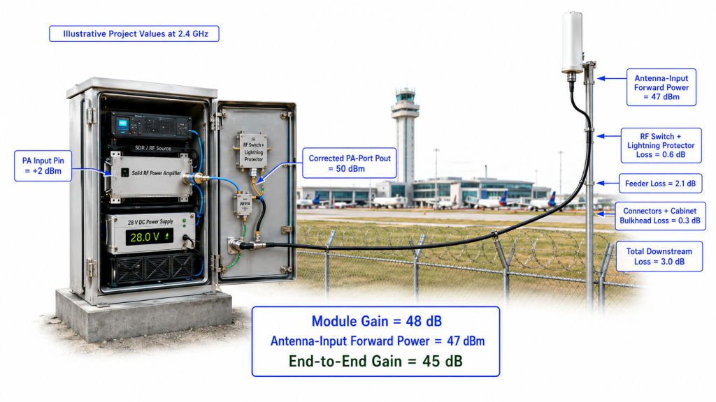
For this illustrative calculation, assume the following verified project values at 2.4 GHz:
- Actual Pin at the PA input: +2 dBm
- Corrected Pout at the PA output: 50 dBm
- RF switch and lightning-protection loss: 0.6 dB
- Verified feeder loss for the defined installed route: 2.1 dB
- Connector and cabinet-bulkhead loss: 0.3 dB
- Total downstream insertion loss: 3.0 dB
The module gain is:
50 dBm − 2 dBm = 48 dB
The antenna-input forward power is:
50 dBm − 3 dB = 47 dBm
The end-to-end gain is:
47 dBm − 2 dBm = 45 dB
The project record should therefore report:
- Module gain: 48 dB
- Verified downstream path loss: 3 dB
- Antenna-input forward power: 47 dBm
- End-to-end gain: 45 dB
In power terms:
- 50 dBm is 100 W
- 47 dBm is approximately 50 W
A 3 dB installed-path loss therefore removes approximately half of the forward power before the antenna-input reference plane.
This does not mean the antenna radiates 50 W. The accepted and radiated powers also depend on reflected power, antenna efficiency, and the remaining antenna-system boundary.
The 47 dBm antenna-input result is also neither a pass nor a fail by itself. The decision depends on:
- The approved antenna-input power requirement
- Measurement uncertainty
- Required operating margin
- Load and VSWR limits
- Thermal and protection behavior
- Required operating duration
The example values illustrate the calculation method. Actual feeder loss must come from the selected cable, final installed length, connector chain, frequency, temperature, installation route, and verified project measurement.
The same boundary applies to rooftop, tower, border, vehicle-mounted, venue, and fixed-site RF systems. The airport installation is one practical integration reference, not a universal feeder-loss value.
4. When Can Path Loss Look Like a Gain-Flatness Failure?
An RF PA may show acceptable gain flatness at its output reference plane while the antenna-input power becomes less flat after the installed path is added.
This occurs because cable and passive-component loss can vary with frequency.
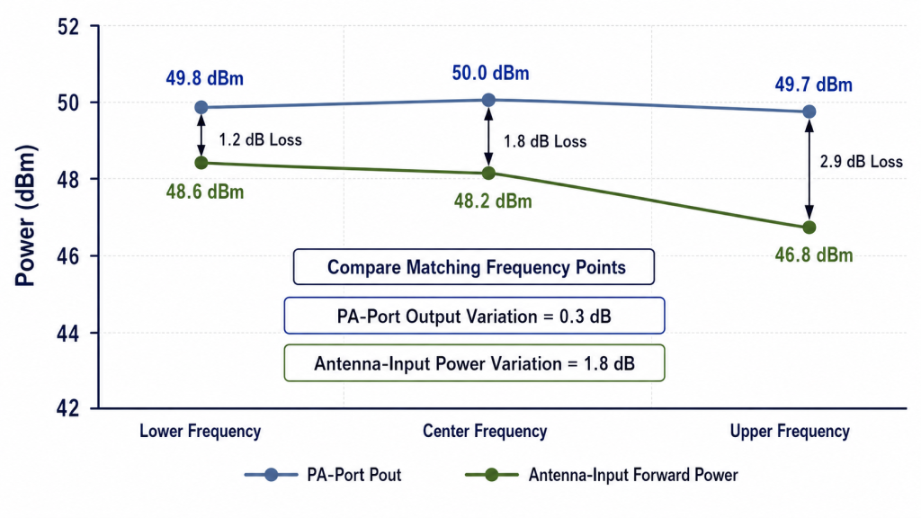
Suppose a corrected PA-port sweep shows:
- 49.8 dBm at the lower frequency
- 50.0 dBm near the center
- 49.7 dBm at the upper frequency
The PA-port output variation is 0.3 dB.
Now assume the verified downstream loss is:
- 1.2 dB at the lower frequency
- 1.8 dB near the center
- 2.9 dB at the upper frequency
The calculated antenna-input forward power becomes:
- 48.6 dBm at the lower frequency
- 48.2 dBm near the center
- 46.8 dBm at the upper frequency
The antenna-input variation is now 1.8 dB, even though the PA-port output remains relatively flat.
A field measurement may therefore look like upper-band PA gain roll-off when much of the slope comes from the installed path.
To locate the boundary, compare the same frequency points for:
- Actual PA-input Pin
- Corrected PA-port Pout
- Module gain
- Verified downstream loss
- Antenna-input forward power
- FWD and REV power or VSWR
- DC voltage and current
- Thermal state
- Protection status
Do not compare a swept PA-port curve with one antenna-input reading at the center frequency.
When one frequency loses usable margin, compare the PA-port gain-flatness result with antenna-input power after the frequency-specific path loss is applied.
Not Every Frequency Difference Is Feeder Loss
An upper-band reduction may also result from:
- Filter insertion-loss variation
- RF switch response
- Connector or adapter discontinuity
- Input-drive variation
- PA compression
- Antenna mismatch
- DC voltage drop
- Thermal drift
- Protection behavior
- Measurement-chain correction error
A correction should be applied only after the source and reference planes are confirmed.
5. What Evidence Separates the PA from the Installed Path?
The strongest evidence follows the RF power through each approved boundary:
Measured Pin → Corrected PA-port Pout → Module gain → Verified downstream loss → Antenna-input forward power → FWD/REV or VSWR → Margin and pass/fail decision
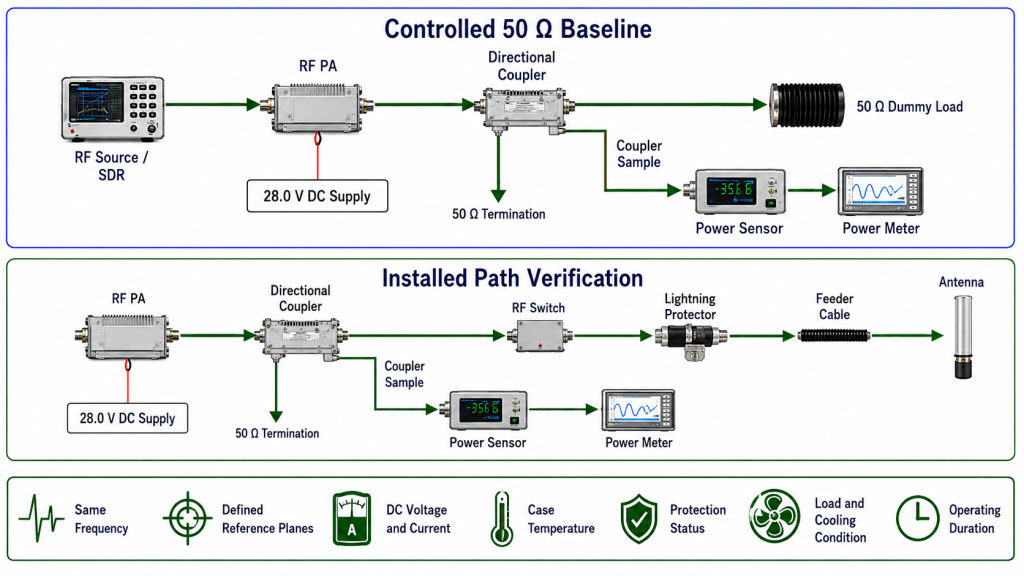
Establish the PA Baseline
A controlled 50 Ω load provides a repeatable baseline for:
- Corrected PA-port output
- Module gain
- DC voltage and current
- Case temperature
- Forward and reflected power
- Protection status
- Frequency-point consistency
However, dummy-load and real antenna-path checks answer different questions.
The dummy load helps establish PA behavior under a controlled load. The installed path helps show what happens after feeder cable, connectors, protection components, and the antenna are connected.
A dummy-load pass does not prove antenna-input power. A weak antenna-input result does not, by itself, prove that the PA failed.
Document the Installed Path
The path record should identify:
- Cable type and manufacturer
- Final installed length
- Required frequency points
- Connector and adapter count
- Cabinet feedthroughs
- Lightning protectors
- RF switches and filters
- Verified insertion loss
- Test equipment and method
- Input and output reference planes
- Configuration revision
A cable datasheet value should not be treated as the complete installed-path loss when the real system also includes connectors, adapters, filters, switches, and protection devices.
Verify the Required Operating Condition
Low-power S-parameter data can characterize a passive RF path. It does not automatically prove full-power or hot-state behavior.
Where required, high-power acceptance should confirm:
- Component power handling
- Connector temperature
- Hot-state path stability
- Corrected PA-port Pout
- Forward and reflected power
- Antenna match
- DC voltage and current
- PA case temperature
- Protection status
- Required operating duration
| Field Observation | Possible Boundary | Evidence Required Before Blaming the PA |
|---|---|---|
| PA-port output passes, but antenna-input power is low | Downstream path loss | Same-frequency loss measurement and labeled reference planes |
| PA-port output drops after the antenna path is connected | Load interaction or PA response | FWD, REV, VSWR, current, temperature, and protection status |
| Upper-band antenna-input power is weak | Frequency-dependent path loss or PA behavior | Matching PA-port and antenna-input frequency data |
| One installed path performs worse than another | Cable, connector, switch, or installation variation | Path-specific loss and configuration records |
| Output falls after extended operation | Thermal or power-handling problem | Time-linked output, current, temperature, and protection data |
| Corrected values differ between test teams | Measurement-chain correction error | Calibration, cable correction, attenuator data, and reference-plane records |
| The corrected result is close to the acceptance limit | Uncertainty or repeatability boundary | Full correction chain, repeat test, rounding rule, and predefined borderline-result treatment |
The evidence should identify where the change begins. More screenshots do not improve the decision unless their reference planes, corrections, and operating conditions are clear.
RFQ: What Must Be Defined Before the PA Is Selected?
An RFQ that asks only for “stable gain” or a wattage class leaves the system boundary undefined.
The request should state whether the required power applies at:
- The PA output connector
- The cabinet output
- The feeder end
- The antenna input
- Another approved project reference plane
It should also distinguish minimum PA-port Pout from minimum antenna-input forward power.
Feeder-Loss-Aware RFQ Checklist
Provide:
- Required frequency range
- Priority frequency points
- Signal or waveform type
- Duty cycle or continuous-wave requirement
- Available Pin at the PA input
- Minimum PA-port Pout
- Minimum antenna-input forward power
- Gain or gain-flatness limits
- Feeder cable type
- Estimated or final feeder length
- Connector, adapter, and bulkhead count
- Lightning protector details
- RF switch or filter stages
- Expected loss at each required frequency
- Antenna or load VSWR boundary
- Reflected-power limit
- DC supply voltage and current capability
- Cooling and mounting condition
- Operating temperature and duration
- Approved reference planes
- Measurement uncertainty and acceptance margin
- Borderline-result treatment
- S/N-linked test-report requirement
When the feeder route is not final, provide the expected cable type, minimum and maximum length, and likely connector count. The supplier can then review a realistic path-loss range instead of assuming an ideal installation.
Before selecting a higher PA power class, calculate the required RF power margin after feeder and connector loss.
A larger PA cannot correct:
- An undefined reference plane
- An unsuitable feeder
- An unstable connector
- A high-loss passive path
- Severe antenna mismatch
- Incorrect measurement correction
Once the required PA-port output, downstream loss allowance, antenna-input target, and operating margin are defined, standard and custom RF PA configurations can be compared against the same project boundary.
Conclusion
Feeder loss does not automatically reduce RF power amplifier gain measured between the approved PA input and output reference planes.
It reduces forward power after the PA output. This lowers antenna-input forward power and end-to-end gain.
The judgment changes when the installed path also changes the PA operating condition. Reflected power, mismatch, heating, DC variation, or protection rollback can reduce corrected PA-port Pout. These effects must be evaluated separately from ordinary downstream insertion loss.
A reliable approval record should show:
- Actual PA-input Pin
- Corrected PA-port Pout
- Module gain
- Frequency-specific downstream loss
- Antenna-input forward power
- FWD and REV power or VSWR
- DC and thermal conditions
- Protection status
- Measurement uncertainty
- Final margin and pass/fail boundary
This prevents normal feeder loss from being misreported as weak PA gain. It also prevents a real load-related PA problem from being hidden inside one generic path-loss value.
RF SKYPOWER can review the required PA-port output, downstream loss allowance, and antenna-input margin before the RF PA power class is finalized.
Submit the required frequency range, waveform, duty cycle, available Pin, and required PA-port or antenna-input power.
Also define the feeder route, passive components, VSWR boundary, DC supply, cooling condition, deployment layout, and required S/N-linked test evidence.