










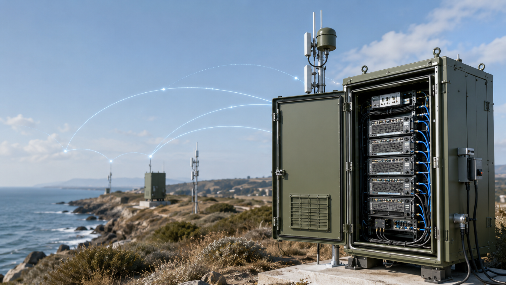
RF PA gain feedback can look normal while the required RF output is still missing. The controller may show PA ON, acknowledge every command, display the requested attenuation, and report no active alarm—yet the installed system still fails its output target.
The customer then faces an expensive decision: increase the input drive, reject the RF PA, revise the control software, or send an engineer to inspect a remote site. Choosing the wrong direction can waste days while the real problem remains hidden.
If the screen says the PA is ON and the “gain feedback” is normal, why is the required RF output still wrong—and which displayed value should you trust?
1. What Does RF PA Gain Feedback Actually Mean?
“RF PA gain feedback” is a project-defined label rather than one universal RF measurement.
Depending on the PA, controller, and software implementation, it may refer to:
- A requested gain or attenuation value
- A value echoed by the controller software
- A command acknowledgement
- An independently reported active setting
- A PA enable or ready state
- A forward-power detector output
- A reflected-power detector output
- A VSWR, temperature, voltage, or current alarm
- A controller-calculated gain value
- Measured gain based on valid Pin and corrected Pout
These values belong to different evidence levels.
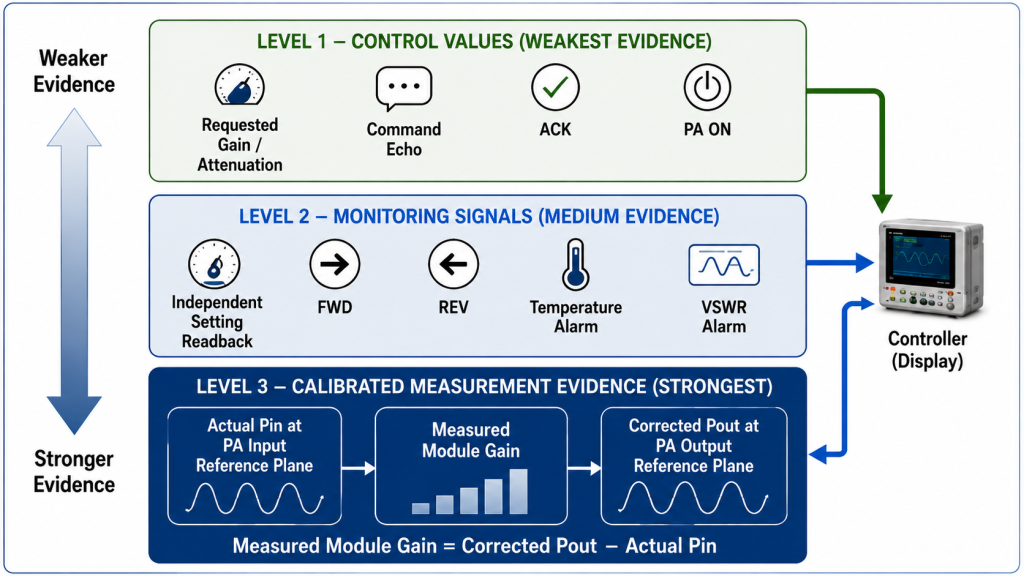
| Signal or Displayed Value | Typical Physical Source | What It Can Prove | What It Cannot Prove Alone | Required Definition |
|---|---|---|---|---|
| Requested gain or attenuation | Controller command | What the controller requested | Whether the PA accepted or applied it | Units, range, command format |
| Displayed command value | Controller software or command echo | What the controller last sent or displayed | Independent PA state or RF result | Data source, echo/readback distinction |
| Command acknowledgement | Communication interface | The command was received or accepted as defined | Setting applied, RF ready, or output stable | ACK meaning, timeout, retry rule |
| Independent setting readback | PA register or hardware state | The active setting, if independently reported | Actual Pout or measured gain | Source, units, update timing |
| Enable or PA ON state | Controller logic or PA status output | Requested or reported enable state | RF input, RF output, or gain | Physical source, active logic, validity |
| FWD indication | Directional detector or coupler path | Relative or calibrated forward response at a defined plane | Measured gain without valid Pin | Scaling, correction, tolerance, reference plane |
| REV indication | Reflected-power detector | Relative or calibrated reflected response | Exact antenna-end mismatch at another plane | Coupler plane, scaling, directivity |
| Alarm or protection state | Threshold and logic circuit | A defined threshold or protection state | Exact RF output or gain | Threshold, delay, latch, reset |
| Controller-calculated gain | Software calculation | Gain if valid Pin and corrected Pout are used | Independent proof of the source data | Equation, timing, corrections, validity |
| Measured module gain | RF measurement system | Gain under the defined operating condition | System gain after downstream path loss | Pin, Pout, reference planes, uncertainty |
The term “feedback” should therefore be replaced by the specific signal name whenever possible, and the RF PA control interface should define the source, direction, and valid state of each signal.
Instead of writing:
Gain feedback is normal.
The system should report something more precise, such as:
- Attenuation command accepted
- Active attenuation register reports 6 dB
- FWD detector output is 1.8 V
- Corrected PA-port Pout is 49.6 dBm
- VSWR alarm is inactive
- Temperature alarm was triggered at the defined threshold
Specific labels prevent a control value from being mistaken for RF acceptance evidence.
2. How Must Measured RF PA Gain Be Verified?
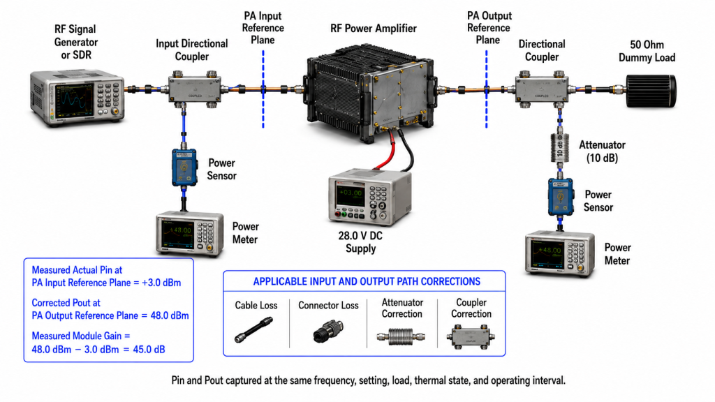
Measured module gain under a defined operating condition requires two valid RF power values:
Measured module gain (dB) = Corrected Pout at the PA output reference plane (dBm) − Actual Pin at the PA input reference plane (dBm)
For example:
- Actual Pin at the PA input reference plane: +3 dBm
- Corrected Pout at the PA output reference plane: 48 dBm
The measured module gain is:
48 dBm − 3 dBm = 45 dB
This calculation proves gain only between the approved PA input and PA output reference planes.
It does not include:
- Feeder loss
- RF switch loss
- Filter loss
- Connector loss
- Cabinet feedthrough loss
- Antenna-path loss
- Antenna mismatch or efficiency
Those belong to a downstream system boundary.
Required Measurement Conditions
A valid gain record should identify:
- Test frequency
- Signal or waveform type
- Duty cycle
- Actual Pin
- Pin reference plane
- Corrected Pout
- Pout reference plane
- Cable, connector, attenuator, and coupler corrections
- DC voltage and current
- Load condition
- Cooling method
- Case or defined thermal state
- Operating duration
- Protection status
- Measurement uncertainty
The same measurement discipline applies when comparing small-signal and large-signal RF PA gain.
Pin and Pout Must Belong to the Same Operating Interval
Pin and Pout must represent the same:
- Frequency
- Control setting
- Load condition
- Thermal state
- Time interval
A delayed, averaged, or stale detector value should not be combined with a current Pin value to calculate gain.
For example, a controller may update Pin every 100 ms while the FWD detector value is averaged over two seconds. If the attenuation setting changes between those readings, the calculated gain can be wrong even though both displayed values appear valid.
The acceptance plan should therefore define:
- Sampling interval
- Feedback latency
- Averaging method
- Data-valid indication
- Timestamp source
- Time synchronization
- Settling time after enable, frequency, or gain-setting changes
Controller-Calculated Gain
A controller-calculated gain value can be useful when:
- Pin is measured at the PA input plane
- Pout is calibrated to the PA output plane
- Both values belong to the same operating interval
- Frequency-specific corrections are applied
- The detector remains within its valid range
- The data-valid state is known
- Measurement uncertainty is understood
- The result is periodically checked against calibrated RF instruments
It is not reliable when the controller subtracts:
- A nominal SDR command value
- A driver setting
- An assumed cable loss
- An uncalibrated FWD voltage
- A stale detector value
A displayed gain value should not be labelled “measured gain” unless the underlying Pin, Pout, corrections, timing, and reference planes support that claim.
3. Why PA ON, ACK, and Setting Readback Do Not Prove Gain
Control state and RF performance state must be separated.
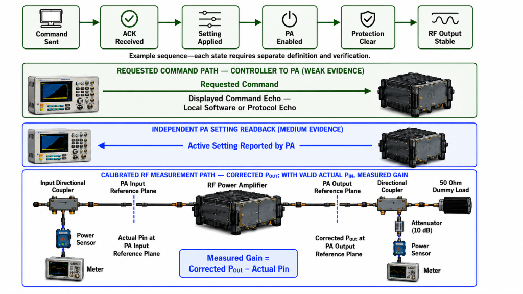
A simplified sequence may include:
Command Sent → ACK Received → Setting Applied → PA Enabled → Protection Clear → RF Output Stable
The exact stages depend on the approved interface. They should not be compressed into one generic “OK” status.
PA ON or Enable State
A PA ON value may represent:
- A command sent by the controller
- A logic output applied to the PA
- A software-maintained requested state
- An independently reported PA enable state
Its physical source must be identified.
A requested enable state does not prove:
- Actual RF input is present
- RF output is present
- Output reached the required level
- The correct channel is active
- Gain is within tolerance
- The PA is free from compression or protection rollback
Even a module-reported enable state normally proves only the defined enable condition.
Command Acknowledgement
An ACK may mean:
- Message received
- Syntax accepted
- Command queued
- Setting stored
- Setting applied
- RF path ready
The protocol must define which meaning applies.
An ACK does not automatically prove that:
- The requested setting took effect
- The RF output stabilized
- The correct path was selected
- The measured gain changed
- The PA completed thermal or protection recovery
Detailed AT command acknowledgement and RF-ready timing should be verified separately from measured RF performance.
Command Echo Is Not Independent Readback
A controller may send a 10 dB attenuation command and then display 10 dB on the screen.
That displayed value may be:
- The last transmitted command
- A local software variable
- A PA register response
- A verified hardware state
These are not equivalent.
A controller echoing the requested value is not an independent setting readback. The interface must identify whether the displayed value comes from the transmitted command, a PA response, or a separately verified hardware state.
Setting Readback Is Still Not RF Gain
Even a valid setting readback proves only the active control setting.
It does not prove:
- Actual Pin
- Corrected Pout
- Gain
- Compression margin
- Frequency flatness
- Thermal stability
- Load behavior
A 6 dB attenuation readback may be correct while the PA output is still wrong because of:
- Input-drive error
- Bias condition
- Frequency response
- Compression
- DC voltage drop
- Thermal rollback
- Load mismatch
- Protection action
The control value and resulting RF output must therefore be verified separately.
4. What Can FWD, REV, Temperature, and Alarm Signals Prove?
Detector and alarm signals can greatly improve diagnosis when their physical meaning is controlled.
They should not be treated as interchangeable substitutes for measured gain.
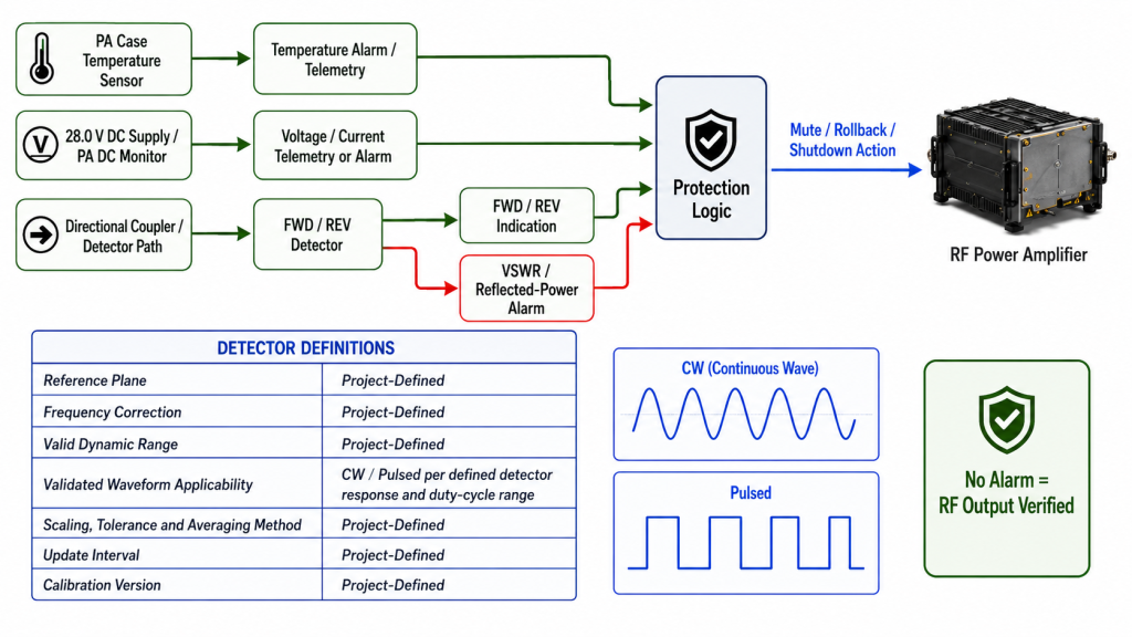
Forward-Power Indication
A FWD output may be provided as:
- Analog voltage
- Digital detector count
- Relative percentage
- Calibrated dBm
- Threshold state
- Alarm bit
A forward-power indication should not be reported as corrected PA-port Pout until the following are defined:
- Detector source
- Coupling factor
- Voltage-to-power or count-to-power conversion
- Frequency correction
- Detector tolerance
- Reference plane
- Valid dynamic range
- Temperature dependence
- Update interval
- Averaging method
- Calibration version
Without this information, FWD feedback may still show relative changes. It may indicate that output increased after a setting change or disappeared after a protection event.
It should not be used as formal output-power acceptance evidence unless its calibration and uncertainty support that purpose.
Waveform and Duty-Cycle Dependence
Detector response may depend on:
- CW or modulated operation
- Crest factor
- Pulse width
- Duty cycle
- Detector bandwidth
- Peak, average, or envelope response
- Averaging time
A conversion established with CW should not automatically be applied to pulsed or high-crest-factor signals.
The approved detector definition should state whether the output represents:
- Peak power
- Average power
- Envelope level
- A filtered relative indication
- A threshold comparison
Reflected-Power and VSWR Indication
REV feedback can help identify:
- Antenna mismatch
- Open or damaged feeder paths
- Connector faults
- RF switch problems
- Load changes
The result belongs to the detector’s reference plane.
A reflected-power value measured near the PA output is not automatically the same as the mismatch at the antenna connector. Feeder attenuation and intervening passive components can change the relationship between those planes.
A VSWR alarm may prove only that a defined mismatch threshold was crossed. It does not necessarily provide:
- Exact forward power
- Exact reflected power
- Exact VSWR
- Fault location
- Antenna-end condition
Temperature, Voltage, and Current Signals
These signals may be provided as:
- Discrete alarms
- Analog values
- Digitally reported measurements
- Latched protection states
The RFQ must not assume continuous telemetry when the interface provides only an alarm.
Temperature, voltage, and current feedback may explain why RF output changed, but they do not directly measure gain.
The applicable RF PA alarm threshold evidence should define:
- Threshold
- Sensor or measurement location
- Trigger delay
- Hysteresis
- Latch behavior
- Protection action
- Reset condition
- Recovery condition
No Alarm Does Not Prove Normal Operation
The absence of an alarm is meaningful only when the following have already been verified:
- Alarm function is enabled
- Threshold is correct
- Channel mapping is correct
- Communication is healthy
- Sensor input is valid
- Data is current
- Alarm is not masked
- Reset and latch logic are understood
“No alarm displayed” proves only that no active alarm is currently being reported through the defined path.
It does not automatically prove that:
- Temperature is normal
- VSWR is acceptable
- Supply voltage is correct
- Current is within range
- The PA is producing RF output
Feature Ownership
Not every value shown in a C-UAS interface comes directly from the RF PA.
The PA module may provide:
- Enable status
- Alarm output
- Detector voltage
- Temperature output
- Communication response
The cabinet controller or C2 software may generate:
- Frequency label
- Channel identity
- Site ID
- Timestamp
- Event history
- Calculated gain
- Maintenance classification
The acceptance record should identify which device generates each value and which software or calibration version interprets it.
5. How Should a Remote C-UAS Site Diagnose a Weak RF Result?
Remote C-UAS sites benefit from feedback because physical access may be difficult. Feedback is useful only when it directs the operator to the correct measurement boundary.
Consider a representative border or coastal site.
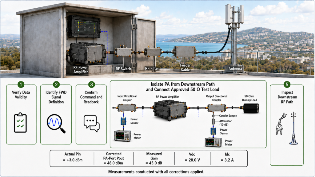
The controller displays:
- PA ON
- ACK received
- No VSWR alarm
- No temperature alarm
- FWD indication below the expected value
This information narrows the investigation, but it does not prove low PA gain.
Step 1: Verify Data Validity
Before interpreting the values, confirm:
- Communication is active
- Data-valid state is true
- Values are current
- Timestamp is correct
- Channel mapping is correct
- Alarm functions are enabled
- No status is being echoed or cached
Step 2: Identify the FWD Signal
Determine whether the FWD value is:
- Relative detector voltage
- Digital count
- Percentage
- Calibrated power value
- Threshold state
- Controller-converted result
Then confirm:
- Reference plane
- Frequency correction
- Waveform and duty-cycle applicability
- Detector range
- Averaging method
- Update interval
- Calibration version
Step 3: Confirm Requested and Reported Settings
Check:
- Enable command
- Mute state
- Gain or attenuation command
- ACK meaning
- Independent setting readback, if supported
- Frequency or channel selection
- RF-ready state
- Protection-clear state
Do not treat a software echo as independent PA readback.
Step 4: Measure Pin and Corrected PA-Port Pout
Record:
- Actual Pin at the PA input plane
- Corrected Pout at the PA output plane
- Frequency
- Waveform and duty cycle
- DC voltage and current
- Case temperature
- Load condition
- FWD and REV data
- Protection status
- Operating duration
If measured module gain passes, the PA may be operating correctly even when the remote FWD display appears low.
Step 5: Check the Downstream RF Path
When PA-port output passes but the field result remains weak, inspect:
- Feeder loss
- Connector condition
- RF switch state
- Filter insertion loss
- Lightning protection
- Antenna match
- Cable routing
- Antenna orientation
- Downstream reference planes
| Observed State | What Is Already Known | What Is Still Unknown | Next Check |
|---|---|---|---|
| PA ON, ACK received, FWD low | Command exchange and displayed status are responding as defined | Actual Pin, calibrated Pout, detector validity | Verify FWD definition, then measure Pin and Pout |
| Command value and displayed value match | Controller values are consistent | Whether the value is an independent PA readback | Identify echo, register response, or hardware-state source |
| Setting readback is correct, Pout is low | Reported control state may be correct | Actual gain and PA operating condition | Check Pin, DC, load, temperature, and protection |
| FWD is normal, field result is weak | PA-side forward indication may be normal | Downstream path and antenna condition | Check feeder, switch, filter, connectors, and antenna |
| No alarm is displayed | No active alarm is currently reported | Alarm enable, threshold, channel health, and data freshness | Verify alarm mapping, communication, and valid-state indication |
| VSWR alarm is active | Mismatch threshold was crossed | Fault location and exact load condition | Inspect feeder, connectors, switch, and antenna |
| Temperature alarm is active | Thermal threshold was crossed | Cooling cause and RF effect | Check airflow, heatsink, duty cycle, and Pout |
| ACK received, no RF output | Command path is responding | Enable sequence, mute, protection, and RF-ready state | Check timing and measure PA-port output |
| Feedback changed after a software update | Display interpretation changed | PA hardware condition | Verify protocol, scaling, mapping, and calibration version |
For remote border and coastal C-UAS projects, the purpose of feedback is not simply to display more values. It is to reduce unnecessary site visits and identify which physical boundary should be checked next.
RFQ: What Must Be Defined Before Feedback Is Approved?
Do not request only “RF PA gain feedback.”
Define each control, feedback, alarm, and measurement requirement individually.
Control Requirements
Specify:
- Interface type
- Logic levels
- Communication protocol
- Command format
- Enable and mute behavior
- Gain or attenuation range
- Setting resolution
- Command direction
- ACK definition
- Timeout and retry rule
- RF-ready definition
- Settling time after a command change
Readback and Detector Requirements
Specify:
- Whether setting readback is required
- Whether readback is independent or echoed
- FWD signal format
- REV signal format
- Analog or digital output
- Voltage-to-power conversion
- Reference plane
- Detector range
- Detector tolerance
- Frequency correction
- Waveform applicability
- Peak, average, or envelope response
- Duty-cycle range
- Sampling interval
- Averaging method
- Feedback latency
- Data-valid indication
Alarm and Telemetry Requirements
Specify:
- VSWR or reflected-power threshold
- Required temperature alarm or telemetry
- Voltage/current alarm or telemetry
- Threshold tolerance
- Trigger delay
- Hysteresis
- Latch behavior
- Reset behavior
- Recovery behavior
- Sensor location
System-Mapping Requirements
Specify:
- Channel identity owner
- Frequency mapping owner
- Site ID owner
- Timestamp source
- Time-synchronization method
- Event-log owner
- Controller software version
- Protocol-map version
- Calibration-file version
Acceptance Requirements
Specify:
- Required test frequencies
- Signal or waveform type
- Duty cycle
- Actual Pin
- Corrected Pout
- Gain calculation
- Approved reference planes
- DC voltage and current
- Load and cooling conditions
- Thermal state
- Alarm-threshold verification
- Detector-scaling verification
- Command and readback timing
- Required operating duration
- Measurement uncertainty
- S/N-linked test evidence
The feedback boundary should be confirmed for the selected Custom RF Power Amplifier Modules configuration rather than assumed from a generic interface label.
Conclusion
RF PA gain feedback does not have one universal meaning.
A displayed value may represent:
- A requested command
- A controller echo
- An independent setting readback
- A detector indication
- An alarm state
- A software calculation
- A measured RF result
These values must not be treated as interchangeable.
Measured module gain requires:
- Actual Pin
- Corrected Pout
- Defined PA reference planes
- Matching frequency and operating interval
- Controlled waveform and duty cycle
- Documented corrections
- Valid data timing
- Known uncertainty
A strong control system does not simply show more values. It identifies the physical source, ownership, reference plane, calibration, waveform applicability, timing, and evidentiary limit of every value.
RF SKYPOWER can review the required control, detector, alarm, and readback boundaries before the RF PA configuration is finalized.
Submit the frequency range, waveform, duty cycle, target output, available Pin, control interface, gain or attenuation command requirement, required setting readback, FWD/REV indication format, alarm or telemetry requirements, detector timing, controller mapping, and S/N-linked acceptance evidence.