










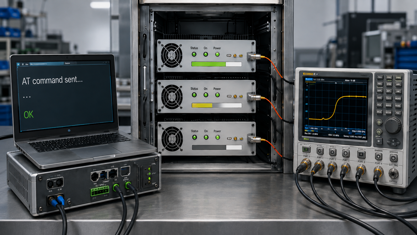
An AT command can return OK according to its protocol definition without proving that a separate RF-ready condition has been reached.
Depending on the command implementation, the requested PA state may still require status confirmation, protection clearance, or RF stabilization after the command itself has completed.
The risky assumption is not that OK always means one specific thing. It is treating command completion, PA enable, protection clear, and RF-ready as the same event without first defining what each protocol response actually proves.
That distinction becomes more important when several PA modules or channels share one controller, one DC bus, or one coordinated startup sequence.
Before RFQ or acceptance, which AT command timing states must be separated—and what evidence proves the controller waited for the correct completion event before declaring the PA cabinet ready?
1. What Must AT Command Timing Define Between Command Sent and RF Ready?
AT command timing is not only the delay between two text commands.
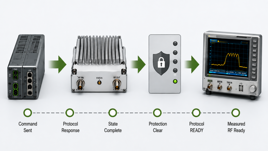
It is the relationship between several events that may occur at different times:
- the controller transmits a command;
- the interface receives the command;
- the protocol returns a defined response;
- the requested operating state begins to change;
- the requested state reaches its defined completion condition;
- protection status becomes valid;
- status feedback is updated;
- and, where required, measured RF output reaches the project-defined ready condition.
These events should not be treated as interchangeable.
AT Timing State Boundary
| State | What It Can Prove | What It Does Not Automatically Prove |
|---|---|---|
| Command sent | Controller transmitted the request | PA received or processed it |
Protocol response / OK / ACK | The response defined for that command occurred | Any PA operating state not explicitly included in that response definition |
| PA enabled | Enable state has started or been confirmed as defined | RF output is stable |
| Protection clear | No blocking protection state is reported at that check | Target RF output has been reached |
| Protocol READY | The protocol-defined ready condition is reported | Measured RF performance unless explicitly included in that definition |
| Measured RF ready | The defined RF acceptance condition has been measured | Every required cabinet channel is ready unless all required channels are checked |
| Cabinet ready | All project-defined module or channel conditions are satisfied | Future operation will remain fault-free |
The meaning of OK, ACK, READY, or any other response must come from the actual command specification.
For example, if the command specification defines OK only as successful command completion, that result must not be extended into proof of RF readiness unless the same specification explicitly defines RF readiness as part of that command’s completion condition.
The same caution applies to status feedback.
A reported ON state proves only the state defined by that status field. It should not be treated as RF-performance evidence unless that relationship has been explicitly defined and validated.
For complete status mapping, keep state definitions in the dedicated RF PA status feedback workflow rather than expanding every feedback case inside the timing page.
2. Which Timing Parameters Must Be Defined for Multi-Band PA Control?
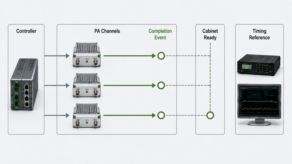
A multi-band cabinet may contain several PA modules, channels, or controlled RF paths.
They do not necessarily complete every command at the same instant.
The controller therefore needs more than a command list. It needs a timing contract.
Important timing parameters include:
- command transmission interval;
- minimum inter-command delay;
- command-response timeout;
- state-completion timeout;
- status polling interval;
- retry interval;
- maximum retry count;
- module or channel addressing rule;
- enable sequence;
- reset behavior;
- post-enable settling condition;
- protection-clear check;
- protocol-ready condition;
- and measured RF-ready criterion where required.
Every timing value needs a reference
A timing value such as 20 ms, 100 ms, or 500 ms is incomplete unless the test defines what starts the clock and what stops it.
Every timing requirement should define:
- start event;
- stop event;
- observation point;
- clock or timebase used for the measurement.
For example, an ACK-latency test may measure from the end of command transmission at the controller interface to receipt of the complete protocol-defined response at that same interface.
A state-completion latency may instead stop when a defined status field changes.
A measured RF-ready latency may stop only when the agreed RF criterion is reached.
Those are different measurements and should not share one timing label unless their event definitions are identical.
Inter-command delay
An inter-command delay prevents the controller from sending the next operation before the previous command has reached the state required by the protocol or system logic.
The correct delay should not be guessed from a generic value.
It depends on what completion event the system is waiting for.
For one command, the protocol-defined response may be sufficient.
For another command, the controller may need to wait for:
- a status-bit transition;
- protection clear;
- a defined module-ready response;
- or measured RF stabilization.
Timeout and retry
A timeout is not only a software convenience.
It defines how long the controller will wait for a specified event before deciding that the event did not occur within the allowed window.
If the timeout is shorter than the valid response or state-change time, normal operation can be misclassified as a failure.
If it is excessively long, a real failure may delay recovery.
Retry logic should therefore state:
- which event caused the retry;
- whether the previous command state is known;
- whether the command is safe to repeat;
- how long to wait before retrying;
- how many retries are allowed;
- and what condition forces escalation to a fault state.
Multi-module startup
When multiple PA modules are enabled, the system should distinguish:
- one common control request being transmitted;
- each module returning its defined response;
- each module reaching the required internal state;
- each commanded RF path reaching its required readiness condition;
- and the complete cabinet reaching its system-ready condition.
A simultaneous control request does not guarantee simultaneous completion.
For the broader DC-to-controller-to-SDR-to-PA startup relationship, use the dedicated C-UAS RF power-on sequence rather than turning AT timing into a complete cabinet startup procedure.
3. When Is a Startup Problem Really an AT Timing Problem?
A startup fault can look like a timing problem without actually being caused by timing.
The same visible symptom may come from:
- command sequencing;
- DC-bus behavior;
- startup current;
- status mapping;
- protection logic;
- addressing;
- firmware differences;
- control-interface behavior;
- or unstable RF output.
The useful first question is:
At which boundary did the expected state stop progressing?
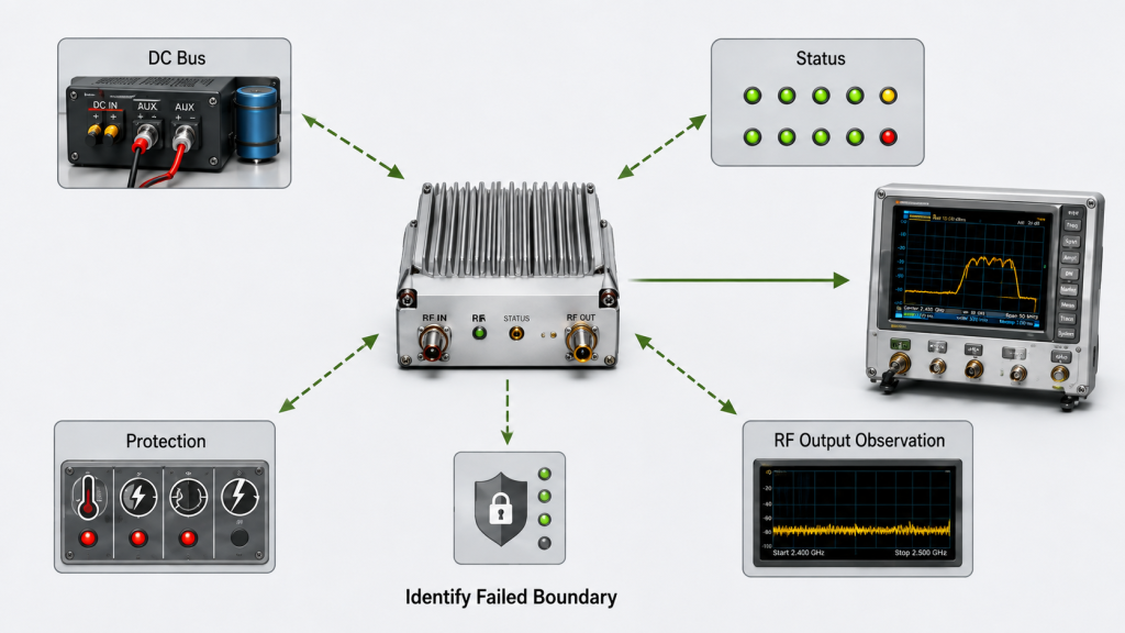
Timing Problem or Another Boundary?
| Observed Symptom | Timing-Related Possibility | Other Boundary to Check |
|---|---|---|
| No protocol response | Command interval, timeout, addressing | Physical or control interface |
| Response received but PA not ready | State-completion timing too short | Enable logic, protection, status definition |
| Current alarm during startup | Several modules enabled too closely | DC bus, supply limit, startup-current behavior |
| READY status appears stale | Polling or update interval | Status mapping, buffering, firmware |
| Protection remains latched | Retry or reset timing may be wrong | Actual protection trigger or recovery rule |
| RF output appears late or unstable | RF-ready sampling occurs too early | Pin, load, DC condition, thermal state |
| One band is missing | Per-channel sequence may be incomplete | Addressing, PA status, source path |
This prevents one common troubleshooting error:
changing AT delays before confirming which state actually failed.
For example, a current alarm during startup should not automatically be solved by inserting a longer command delay.
The event may originate from the DC supply, shared bus, wiring, current limit, or legitimate startup-current behavior.
If RF output instability coincides with source-voltage, PA-terminal-voltage, current/load-state, or protection changes, use the RF PA DC power-chain output-drop review to decide whether the DC chain should remain the primary investigation path.
That electrical boundary belongs in the dedicated RF PA startup current alarm analysis.
Likewise, a missing READY indication may be a status-definition or status-update problem rather than a slow PA.
Before changing timing values, establish whether the failure occurred at:
command transmission → protocol response → state completion → protection clear → protocol ready → measured RF ready
and then route the investigation to the correct technical boundary.
4. How Should AT Timing Interact With Protection and Status Feedback?
AT timing should not operate independently of protection and feedback.
A control sequence becomes more reliable when timing decisions are tied to defined states rather than fixed delays alone.
After an enable command, for example, the controller may need to verify:
- the expected protocol response;
- the module enable state;
- valid status feedback;
- no blocking protection condition;
- protocol READY where implemented;
- and the measured RF-ready condition where required by the project.
The exact sequence depends on the product and protocol.
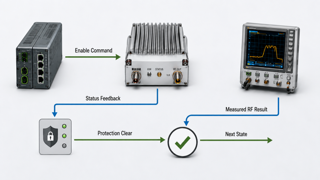
The important point is that the controller must know which event is authoritative for each transition; the broader RF PA control logic definition should then define the system action, timeout, and recovery rule associated with that state.
Protection timing
Protection states can affect whether the next command is valid.
If an over-current, over-temperature, low-voltage, VSWR, or another monitored condition is active, the controller should not assume that repeated enable commands will restore normal operation.
The integration should define:
- which protection states block operation;
- whether the state is latched;
- what recovery condition is required;
- whether reset is manual or automatic;
- when a reset command is allowed;
- what response or status confirms reset completion;
- and what evidence confirms recovery.
The full trigger, shutdown, latch, reset, and recovery logic belongs in the dedicated RF PA protection logic validation process.
AT timing should define only how the controller interacts with those states.
Status timing
Status feedback also needs a defined update model.
The controller should know:
- whether status is event-driven, polled, or both;
- how often it may be queried;
- how quickly a state transition should appear;
- whether stale data can remain in a buffer;
- how channel identity is reported;
- whether responses can arrive out of order;
- and what firmware or command-set version produced the response.
If the interface supports unsolicited or asynchronous status messages, identify them separately from solicited command responses in the log.
READY, alarm, protection, or state-change events should be correlated to their actual source, module, and channel rather than assumed to belong to the most recently transmitted command.
If a control interface itself is not yet defined, timing should not be finalized first.
Physical layer, addressing, command format, enable behavior, reset, alarm, and feedback definitions should be established through the RF PA control interface review before timing limits are treated as final.
5. What Evidence Proves AT-Controlled PA Readiness?
A screenshot showing OK is weak acceptance evidence.
A stronger AT timing record connects the command sequence with the actual protocol states, PA states, and—where required—the measured RF state.
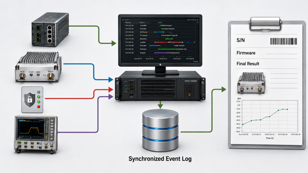
Useful evidence may include:
- module S/N;
- hardware version where applicable;
- firmware version;
- controller software version;
- command sent;
- module or channel address;
- command timestamp;
- protocol response;
- response timestamp;
- status response;
- enable-state transition;
- protection state;
- protocol READY state where applicable;
- timeout or retry event;
- Vdc and Idc where relevant;
- measured RF output where required;
- RF measurement reference plane;
- and final acceptance result.
The goal is not to collect the largest possible log.
The goal is to prove that the controller waited for the correct defined event before advancing to the next system state.
Separate protocol readiness from measured RF readiness
A digital READY state proves only the condition defined by the protocol.
If shipment acceptance also requires measured RF readiness, define that criterion separately.
A measured RF-ready definition may need to specify:
- RF measurement reference plane;
- required corrected output range or tolerance;
- waveform;
- duty cycle where applicable;
- load or VSWR condition;
- input-drive condition;
- DC operating condition;
- thermal state;
- stabilization window;
- measurement method;
- and applicable measurement uncertainty.
Do not present a READY bit or status string as proof of RF performance unless that relationship has been explicitly defined and validated.
Timestamped evidence
For timing acceptance, timestamps should be associated with meaningful events.
A useful record may show:
Command transmitted → defined response received → state changed → protection clear → protocol READY → measured RF-ready criterion met
The report should also identify which timestamps come from:
- the controller;
- the PA;
- external instrumentation;
- RF test equipment;
- or another logging system.
When timestamps come from different devices, use a common timebase where practical or document:
- clock offset;
- synchronization method;
- timestamp resolution;
- clock drift where relevant;
- and timing uncertainty.
Without that information, millisecond-scale differences from separate logging systems should not be treated as exact.
Solicited and asynchronous messages
If the protocol supports unsolicited or asynchronous result messages, the test log should distinguish them from solicited command responses.
For each asynchronous event, record where practical:
- source module;
- channel;
- event type;
- timestamp;
- related protection or status condition;
- and whether the event is associated with a previous command or occurred independently.
This is especially important in multi-module systems where several channels may change state while the controller is also sending new commands.
Fixed delay versus state-based completion
A fixed delay can be sufficient when:
- the module behavior is defined and repeatable;
- the delay includes the required margin;
- and acceptance evidence shows that the required state consistently completes within that window.
A state-based method can be stronger when the controller can directly confirm the event that actually matters.
For example:
- wait for the defined protocol READY condition;
- verify protection clear;
- then confirm the measured RF-ready condition if required.
The choice should follow the actual interface capability rather than assuming one method is always superior.
For multi-band systems, the final cabinet-ready rule should identify whether readiness requires:
- all PA modules;
- all commanded channels;
- only active channels;
- or another project-defined subset.
6. What Should the RFQ Define for AT Command Timing Acceptance?
“Supports AT commands” is not a complete control requirement.
Two PA modules may both support AT control while differing substantially in:
- command behavior;
- response meaning;
- completion timing;
- status-feedback method;
- asynchronous event reporting;
- protection interaction;
- timeout behavior;
- recovery logic;
- and RF-ready definition.
The RFQ should therefore define both the required control function and the evidence needed to accept it.
AT Timing RFQ Acceptance Evidence
| Parameter | Definition Required | Evidence | Acceptance Decision |
|---|---|---|---|
| Control interface | Physical layer and communication method | Interface specification | Compatible with controller |
| Command set | Required commands, syntax, and version | Command document | Required functions supported |
| Response definition | What OK, ACK, or another result actually proves | Protocol specification plus logged response | Response meaning is unambiguous |
| Timing reference | Start event, stop event, observation point, and timebase | Timestamped log with defined timing basis | Reported latency is reproducible and comparable |
| Inter-command delay | Minimum spacing or state-completion rule | Timestamped command log | No premature next command |
| State-completion timeout | Expected event and maximum allowed completion time | State/status log | Required state reached within the agreed rule |
| Polling interval | Allowed status-query rate and update model | Communication log | No invalid polling or stale-state ambiguity |
| Retry behavior | Trigger, interval, count, repeatability, escalation | Fault/retry log | Predictable recovery behavior |
| Ready definition | Protocol-ready state and, where required, separate measured RF-ready criterion | Status log plus defined RF evidence where applicable | Each required readiness condition proven independently |
| Asynchronous events | Message type, source, channel, and correlation rule | Event log | Events correctly associated with their source |
| Protection interaction | Blocking, latch, reset, and recovery rules | Protection/state log | No unexplained protection behavior |
| Traceability | S/N, firmware, controller version, test version | S/N-linked test report | Test evidence traceable |
For a practical RFQ, specify:
- control interface and physical layer;
- module count;
- addressing method;
- required AT command list;
- command syntax and version;
OK/ ACK / result-code definitions;- protocol READY definition;
- measured RF-ready criterion where required;
- timing start and stop events;
- timing observation point;
- clock or timebase;
- inter-command delay;
- status polling interval;
- command-response timeout;
- state-completion timeout;
- retry interval;
- maximum retry count;
- enable sequence;
- reset behavior;
- protection feedback;
- unsolicited or asynchronous event handling;
- firmware version;
- controller software version;
- DC-bus operating condition where relevant;
- RF measurement reference plane where RF readiness is measured;
- timing uncertainty where multiple clocks or instruments are used;
- and S/N-linked timing records.
When comparing RF Power Amplifier Modules, define the required control interface, AT command timing, response semantics, ready-state logic, protection feedback, timeout behavior, asynchronous event handling, and acceptance evidence before treating control support as integration-ready.
FAQ
Does an AT command OK mean the RF PA is ready?
Not necessarily.
OK proves only what the specific command specification defines it to prove.
For some commands, it may indicate successful command completion. That still should not be extended into proof of a separate PA-ready or measured RF-ready condition unless the protocol explicitly defines that relationship.
How should timeout and retry timing be defined?
Define the event being waited for first.
Then specify:
- start event;
- stop event;
- observation point;
- allowed completion time;
- timeout condition;
- retry interval;
- maximum retry count;
- whether the command is safe to repeat;
- and the fault state used when retries fail.
The timeout should be based on defined module behavior and acceptance evidence rather than an arbitrary software default.
What evidence proves AT command timing before acceptance?
Use traceable event records that connect:
- command transmission;
- protocol response;
- state transition;
- protection status;
- protocol readiness;
- and measured RF readiness where required.
The report should identify the module S/N, firmware and controller versions, module or channel address, timing reference, timebase, retry behavior, asynchronous events where applicable, and final acceptance result.
Conclusion
AT command timing is acceptable only when the meaning and timing of each required event are defined before testing.
An OK, ACK, READY bit, or other protocol response should prove only what the actual command specification says it proves. It should not automatically be extended into evidence of PA enable completion, protection clearance, measured RF readiness, or complete cabinet readiness.
The key engineering question is therefore not simply how many milliseconds exist between commands.
It is:
Which event starts the timing measurement, which event ends it, where those events are observed, and what evidence proves that the required operating state was actually reached?
Where multiple clocks, asynchronous messages, status channels, or RF measurements are involved, those boundaries must also remain traceable. Otherwise, a timing number may look precise while describing different events or different timebases.
Startup-current faults, stale feedback, latched protection, missing channels, and unstable RF output should not all be blamed on AT timing. Identify the failed boundary first, then route the investigation to the relevant power, status, protection, interface, or RF process.
For AT-controlled multi-band RF PA integration, send RF SKYPOWER the control interface, physical layer, module count and addressing plan, command set, result-code definitions, protocol READY definition, RF-ready criterion where required, timing start and stop events, polling interval, timeout and retry rules, asynchronous event handling, enable sequence, DC-bus condition, protection feedback, firmware and controller versions, timebase requirements, RF measurement boundary, and required S/N-linked timing evidence.
Those definitions turn “AT command support” from a feature statement into a reproducible control and acceptance requirement.