










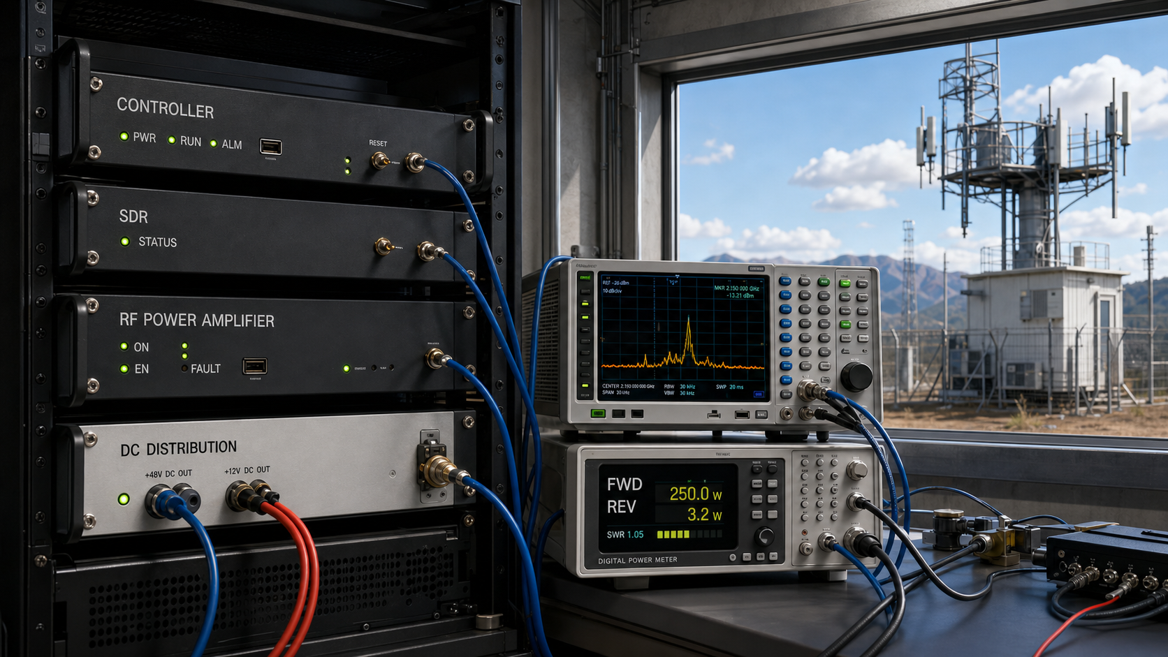
Power-on sequence problems in a C-UAS RF chain rarely look like timing problems at first. The controller may show the SDR as ready, the PA as enabled, no active protection alarm, and still record zero, late, or unstable RF output during startup.
The mistake is to treat those labels as simultaneous proof of system readiness. Each state becomes valid at a different point, and the exact order can change with the system architecture. A clean one-time startup therefore does not prove that the controller sampled the right state—or that the same sequence will survive a cold start, restart, or fault recovery.
Before approving the SDR-to-PA startup, what evidence proves that input drive, protection status, PA enable, and RF output became valid in the intended sequence and at the correct measurement boundary?
1.Which States Must Be Separated in an SDR-to-PA Power-On Sequence?
A power-on sequence is not a single ON command. It is the transition from electrical power being applied to controlled RF output becoming valid.
There is no single universal SDR-to-PA startup order. One architecture may power the PA rail before the SDR output is enabled. Another may initialize the SDR first. The engineering requirement is not to force every system into the same order, but to define when each state becomes valid, which states may overlap, and which conditions must be true before RF drive or system-ready status is allowed.
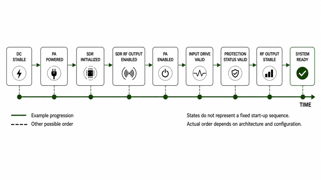
A typical startup may involve:
- DC rail stable
- controller boot complete
- control interface ready
- SDR initialized
- frequency, waveform, and output settings loaded
- PA monitoring available
- PA powered
- PA protection status valid
- PA enabled
- SDR drive applied
- PA output started
- RF output stabilized
- feedback refreshed
- system-ready state declared
The important distinction is between power present, command accepted, state valid, and RF performance verified.
For example, an SDR may finish booting before its RF output is enabled. A PA may have supply voltage before its enable state is accepted. A controller may begin polling protection status before the PA monitoring interface is fully valid. None of those intermediate states alone proves that the RF chain is ready for acceptance sampling.
Protection status may be polled earlier for diagnostics, but it should not be treated as valid readiness or acceptance evidence until the relevant PA monitoring or control interface has reached its defined valid state. An early protection-clear response may be default, stale, or otherwise invalid for the startup decision.
The same principle applies to the SDR Signal Source Module. An SDR output setting does not by itself prove the actual RF power reaching the PA input. If source-path loss, switching, cabling, attenuation, or connectors sit between the SDR and PA, the acceptance boundary must be defined at the PA input or another calibrated in-system reference point.
Power-On State vs Valid Evidence
| Startup State | What It Can Confirm | What It Does Not Prove | Useful Evidence |
|---|---|---|---|
| DC rail stable | Supply has reached the required operating region | Controller or RF path is ready | Voltage trend and timestamp |
| Controller ready | Commands and status polling can begin | SDR or PA RF state is valid | Boot and interface log |
| SDR initialized | Configuration has loaded | RF drive has reached the PA | Ready flag plus output-enable record |
| PA powered | Supply is present at the PA | PA is enabled or producing stable RF | PA power-state feedback |
| Protection clear | No blocking condition is reported at that valid monitoring point | Input drive or RF output is valid | Timestamped protection status |
| PA enabled | Enable condition has been accepted | Output has stabilized | Enable timestamp and status |
| Input drive valid | Defined RF drive is present at the PA-input reference plane | PA output is correct | Calibrated input-power evidence |
| RF output stable | Output has reached the defined acceptance window | Antenna-end power is identical to PA-port power | Pout trend with stated reference plane |
| System ready | All project-required readiness conditions are satisfied according to the defined logic | Anything not included in that definition | Timestamped readiness logic and state record |
The acceptance team should know exactly which conditions create the final system-ready state. A generic green indicator is not enough unless the logic behind it is defined.
2.What Happens When SDR Drive and PA Readiness Cross at the Wrong Time?
The question is not simply whether the SDR or PA turns on first. The real question is whether RF drive, PA readiness, protection feedback, and output sampling occur in the intended relationship.
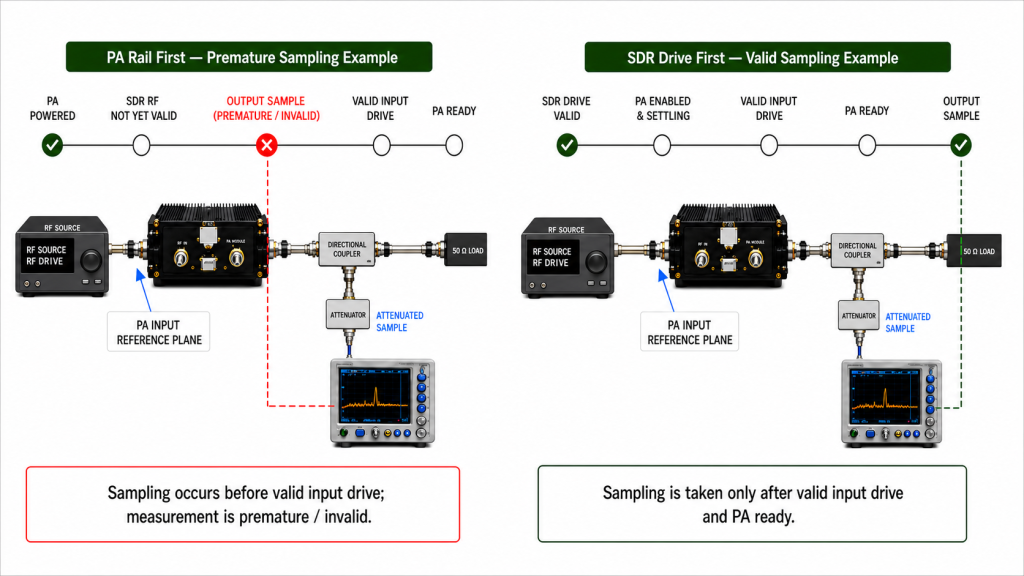
When the PA rail comes up before SDR drive
A PA power rail may become stable before SDR output is enabled without creating a problem. The error begins when the controller treats the powered PA as RF-ready.
If output is sampled before valid drive reaches the PA input, the system may report low output or no output even though the PA itself is healthy. Remote monitoring may display PA ON while the RF chain is still waiting for a valid source condition.
This can lead to:
- false low-output diagnosis
- unnecessary PA replacement
- premature output sampling
- stale protection or status interpretation
- delayed RF appearing as an intermittent PA problem
The correct control boundary is therefore not simply PA powered. It is the project-defined point at which PA state, valid input drive, protection status, and output conditions allow RF verification.
When SDR drive arrives before the PA path is ready
The opposite order can also create misleading symptoms.
The SDR may already be producing RF while the PA is still booting, changing gain or attenuation state, settling a relay or switch path, waiting for enable, or completing protection initialization.
In that condition, the source can appear healthy while the PA output remains absent or unstable.
Engineers should not assume that the programmed SDR output level equals the RF power actually arriving at the PA input. “Input drive valid” should refer to a defined PA-input reference plane or a calibrated in-system indication.
If the RF source path includes cable loss, connectors, switches, attenuators, or other components, those losses must be considered before comparing input drive with PA output.
For PA gain, Pin should refer to the defined PA-input reference plane and Pout to the defined PA-output reference plane. If the calculation extends from the SDR output to the antenna end, it includes additional RF-path losses or gains and should not be presented as PA gain alone.
3.How Wrong Startup Timing Creates False RF PA Faults
A sequencing error can make healthy hardware look defective because the controller tests a state before that state is valid.
The same cabinet may fail during a cold start, work on a second attempt, and then operate normally after a restart. That pattern does not automatically prove an intermittent PA failure. It may indicate that the first startup crosses a timing boundary that later restarts do not.
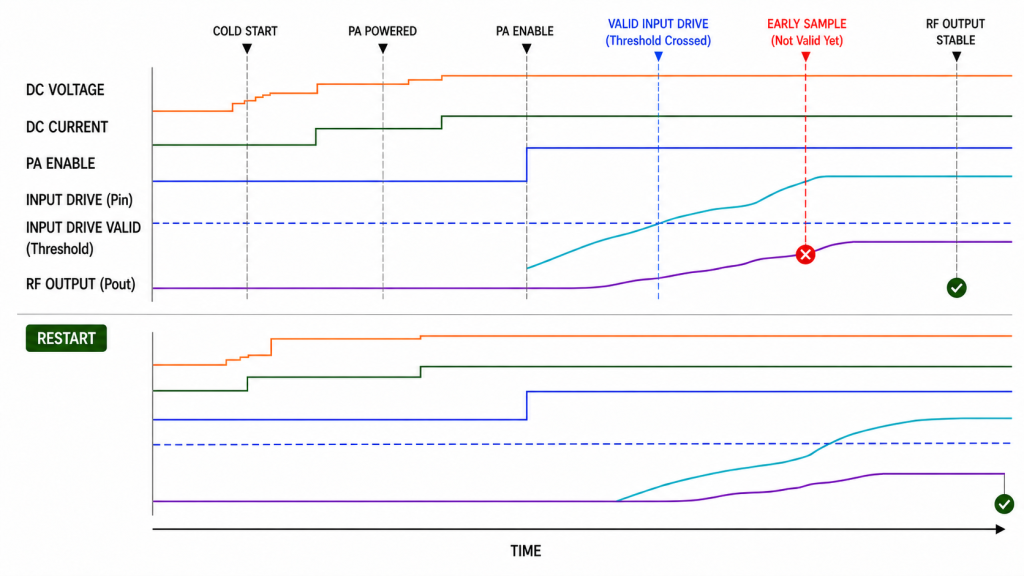
Common symptoms include:
- PA enabled but no RF output
- SDR output present while PA output is missing
- protection alarm appearing only during startup
- output arriving after a delay
- first startup failing while retry passes
- one channel becoming ready later than another
- current surge or voltage sag during enable
- controller timeout during boot
- status feedback remaining stale
- RF output becoming stable after the acceptance window has already closed
- cold-start and restart results disagreeing
Voltage and current transients also need context. A temporary supply sag during PA enable may coincide with unstable output or an alarm, but the acceptance team should not treat one illustrative voltage value as a universal limit.
The project should instead define:
- nominal supply condition
- allowed startup voltage boundary
- allowed current transient
- duration of the transient
- condition for starting RF measurements
- protection behavior if the boundary is exceeded
Only after those conditions are defined can the startup trace distinguish a real power problem from normal transient behavior.
4.What Changes in High-Security C-UAS Startup?
The startup logic should be able to distinguish at least:
- system powered but not ready
- SDR initialized but RF output disabled
- PA powered but not enabled
- protection state not yet valid
- valid PA input drive present
- RF output stabilizing
- RF output accepted
- fault present
- restart or recovery in progress

For remote operation, a single PA ON indicator is weak evidence. The operator should be able to tell whether the system is waiting for source readiness, PA enable, protection clearance, output stabilization, or recovery.
Cold-start and restart behavior should also be compared. If a system works only after a second attempt, the startup evidence should explain why before anyone changes PA gain, SDR output, protection thresholds, or controller code.
Where unattended recovery is required, timeout, retry, reset, and failed-recovery states should be defined rather than allowing an unlimited restart loop.
5.How to Diagnose Power-On Sequence Problems from One Timeline
The most useful troubleshooting method is to place electrical, control, RF-input, protection, and RF-output events on one timestamped timeline.
When those events come from different controllers, instruments, or software logs, their timestamps must share a common trigger or time base, or be aligned with a verified synchronization method. Otherwise, clock offset, logging latency, or trigger delay can be mistaken for a real sequencing error.
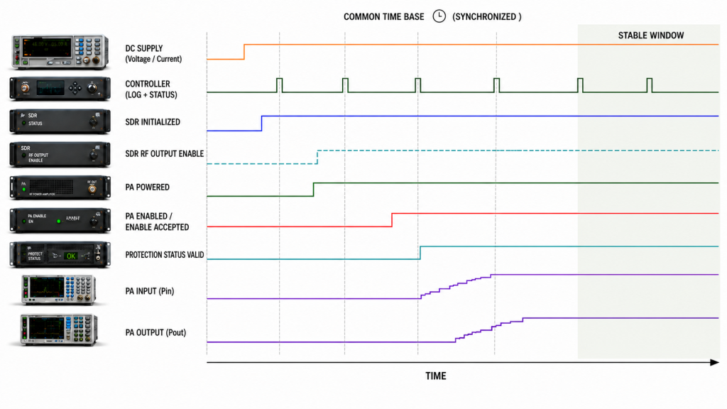
Start with observation before adjustment.
A practical review order is:
- Confirm the DC rail startup trend.
- Identify when the controller becomes operational.
- Confirm when the control interface becomes valid.
- Record SDR initialization and RF output-enable timing separately.
- Separate PA powered, PA enabled, and RF-output-valid states.
- Identify when protection feedback first becomes valid.
- Confirm when RF drive reaches the defined PA-input reference plane.
- Record when PA output first appears.
- Determine when output enters the specified stable window.
- Compare cold start, normal restart, and fault recovery.
- Review timeout, retry, and reset events.
- Use the sequence evidence first to identify which state failed, arrived late, or was sampled before it became valid. Then verify the relevant hardware, control interface, DC supply, RF path, and measurement chain before assigning a root cause.
Do not change gain, SDR drive, timeout values, or protection thresholds merely because output was missing during one startup event. First determine whether the relevant state was supposed to be valid at that moment.
If the unresolved issue is specifically command response, per-channel completion, timeout, or retry behavior, the next review should move to AT command timing rather than changing the whole power-on architecture.
Startup Symptom vs Timeline Check
| Symptom | Sequence Condition to Check First | Evidence Needed |
|---|---|---|
| No PA output | Was output sampled before valid PA input drive? | SDR output, PA-input, and Pout timestamps |
| Startup alarm | Was protection sampled during an invalid or transient state? | Protection log plus voltage/current trend |
| RF appears after retry | Did the first startup cross a timing boundary? | Cold-start vs restart timeline |
| One channel starts late | Does that channel have different enable, command, or settling time? | Per-channel timestamps |
| Output level appears wrong | Were gain/attenuation settings and PA input power valid before sampling? | Setting log and calibrated Pin |
| Remote status looks inconsistent | Was old feedback used to create system-ready? | Polling timestamp and refreshed status |
| Output is unstable only at startup | Did acceptance begin before the output stabilization window? | Time-aligned Pout trend |
This approach prevents a timing problem from being converted too quickly into a module-replacement problem.
6.What Evidence Proves a Valid Power-On Sequence?
A valid power-on sequence should be approved from evidence, not from one successful power-up.
The evidence package should make it possible to reconstruct when each relevant state became valid.
The record should also state how timestamps from different devices or instruments were synchronized and, where timing margin is critical, the expected synchronization or logging uncertainty.
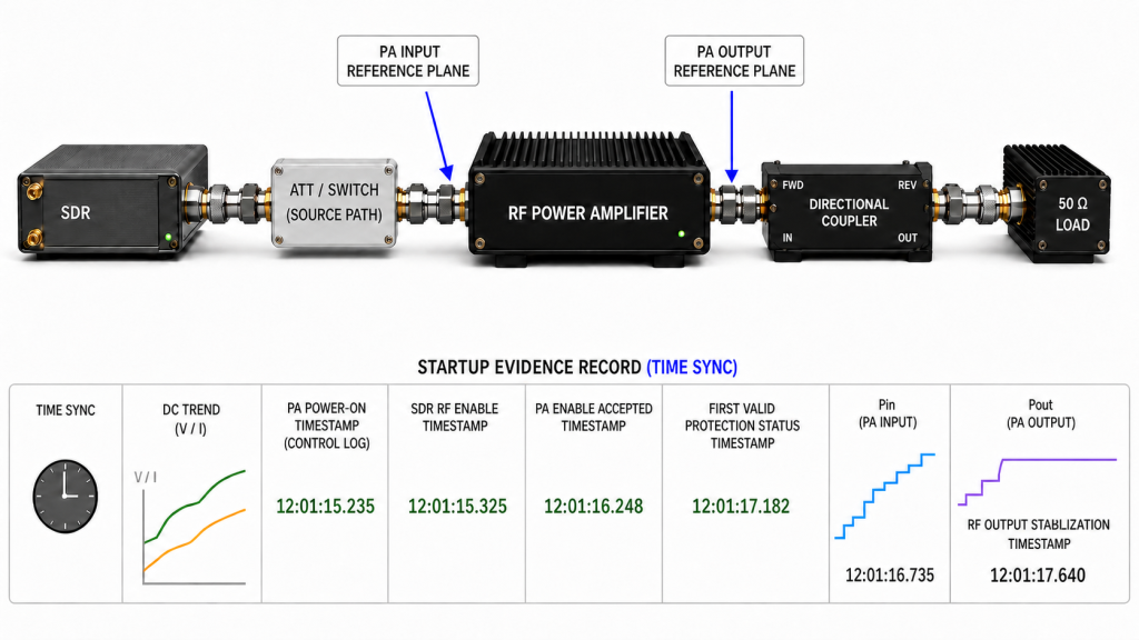
Useful records include:
- DC voltage startup trend
- DC current trend
- controller boot timestamp
- control-interface-ready timestamp
- SDR initialization timestamp
- SDR RF output-enable timestamp
- PA power-on timestamp
- PA enable timestamp
- first valid protection-status timestamp
- PA-input drive evidence
- PA output start time
- PA output stabilization time
- timeout and retry records
- fault and reset records
- cold-start result
- restart result
- hot-state restart result where required
- firmware or control-software version
- channel or module identifier
- S/N-linked acceptance report where per-unit traceability is required
Two measurement boundaries deserve particular attention.
Define the PA-input reference plane
The SDR programmed output is not automatically the PA Pin.
If the signal passes through cable, connectors, switches, attenuation, splitting, filtering, or other source-path elements, the project should define where input power is verified.
If direct measurement at the PA input is impractical in the final cabinet, use a calibrated system indication and document the correction method.
Define the RF-output reference plane
“RF output stable” must also identify where the value applies.
Possible reference planes include:
- PA output connector
- calibrated directional-coupler measurement point
- detector or monitoring channel
- output of a downstream RF path
- antenna-feed or antenna-end boundary
Those numbers are not interchangeable.
If the acceptance value is corrected from another measurement point, the report should record the measured value, correction applied, and final reference plane. Cable, connector, attenuator, and coupler losses should not disappear silently inside a reported Pout number.
The same reference plane should be used consistently when comparing repeated startup tests unless the report explicitly explains the difference.
The stabilization criterion should also match the operating mode, duty cycle, and measurement window defined for acceptance.
7.How to Define a Power-On Sequence Without Assuming One Universal Order
A robust startup design separates states and defines transition rules rather than assuming that one ON command makes the whole RF chain ready.
For each relevant state, define:
- entry condition
- confirmation method
- allowed timing window
- timeout behavior
- fault condition
- retry rule
- recovery rule
- log requirement
A system could, for example, power the PA rail before enabling SDR output. Another could initialize the SDR first while keeping its RF output disabled. Either approach can be valid when the control logic prevents RF acceptance before the required states are confirmed.
The critical design question is:
What must be true before the controller is allowed to declare the RF chain ready?
That answer should be project-specific.
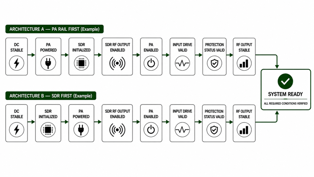
A useful system-ready definition may combine:
- stable DC power
- controller and communication valid
- SDR initialized
- correct SDR settings loaded
- required PA monitoring available
- no active blocking protection state
- PA enable accepted
- valid RF drive at the PA-input reference plane
- PA output inside the required stable range
- required load or antenna-path condition valid
- required status feedback refreshed
Not every project will use every item. The important point is that the definition is explicit.
RF Power Amplifier control logic should separately define enable permission, alarm interpretation, status feedback, timeout behavior, reset, and recovery. The power-on-sequence article should use those states as inputs to startup verification rather than duplicate the full control-logic design.
8.What Should a Power-On Sequence RFQ Define?
“SDR-compatible PA” and “stable startup” are not measurable RFQ requirements.
A stronger RFQ defines what the supplier or integrator must prove from power application to accepted RF output.
Power-On Sequence RFQ & Acceptance Evidence
| RFQ Item | What Should Be Defined | Acceptance Evidence |
|---|---|---|
| System DC supply | Nominal voltage and allowed startup boundary | Vdc startup trend |
| Controller readiness | Condition that allows commands and polling | Boot timestamp |
| SDR readiness | Difference between initialized and RF-output-enabled | SDR state log |
| PA power state | Powered, standby, and enable definitions | PA state log |
| Protection status | When monitoring becomes valid and what blocks output | Timestamped protection log |
| PA-input drive | Required input level and measurement reference plane | Calibrated Pin evidence |
| PA enable | Command, condition, and valid-state timing | Enable timestamp |
| RF output stabilization | Reference plane, operating mode, target window, stabilization criterion, and sampling delay | Time-aligned Pout record |
| Startup current | Allowed transient or project-defined boundary | Idc trend |
| Timeout / retry | Timeout value, retry count, and final failure state | Controller event log |
| Fault recovery | Reset and restart behavior | Recovery timeline |
| Cold start | First startup from a defined OFF condition | Cold-start record |
| Restart | Recovery after reset or software restart | Restart record |
| Hot-state restart | Required only where operating profile demands it | Hot restart evidence |
| Timestamp alignment | Common trigger, time base, or synchronization method and required uncertainty | Synchronization record |
| Firmware / control version | Version used during acceptance | Version-controlled report |
| Traceability | Module or channel identity | S/N-linked record where required |
The RFQ should also state whether output acceptance is required at the PA port or at another system reference plane. If the requirement is antenna-end power, the RF path between the PA and antenna must be included in the correction and acceptance method rather than assuming PA-port Pout is the same value.
When comparing RF Power Amplifier Modules for SDR integration, provide the supplier with the actual control and startup boundary instead of asking only whether the module can be turned on by your controller.
FAQ
Does SDR ready mean the RF chain is ready?
No. SDR ready may mean that initialization or configuration is complete. RF-chain readiness is a separate project-defined state that may also require valid PA status, protection feedback, PA-input drive, PA enable, stable RF output, and refreshed controller feedback.
Can the PA power rail become active before SDR output is enabled?
Yes. In some architectures that is completely acceptable. The important boundary is whether the system prevents premature RF-ready status or acceptance sampling before the required input-drive, protection, PA, and output conditions become valid.
What evidence proves that the power-on sequence is valid?
Use a timestamped startup record that connects DC behavior, controller readiness, SDR initialization and RF enable, PA states, protection feedback, PA-input drive, and RF-output stabilization. The measurement reference planes, synchronization method, timing uncertainty where relevant, and acceptance limits must also be defined so that the timestamps support a valid sequencing conclusion.
Conclusion
A valid SDR-to-PA power-on sequence is not proven because the SDR and PA both turn on. It is proven when the project-defined electrical, control, protection, RF-input, and RF-output conditions are satisfied in the required relationship—and the startup record shows that relationship at clearly defined measurement boundaries and a trustworthy time base.
There is no universal order that every C-UAS RF chain must follow. A PA rail may be powered before SDR output in one architecture, while another system may initialize the SDR first. What matters is that intermediate states are not mistaken for final readiness, protection feedback is treated as valid only after its monitoring boundary is established, PA input power is verified at an appropriate reference plane, and RF output is sampled only after the required stabilization condition is reached.
When sequence timing is compared across multiple controllers or instruments, timestamp alignment must be good enough to support the timing conclusion. Otherwise, logging latency or clock offset can look like a real startup fault.
Cold start, restart, and required recovery conditions should produce repeatable evidence. If those traces disagree, diagnose the failed or delayed state first, then verify the relevant hardware, control interface, DC supply, RF path, and measurement chain before assigning a root cause.
For an SDR-to-PA integration review, provide the SDR output condition, expected PA-input power at the defined reference plane, target PA-port or antenna-end output, DC supply, duty cycle, cooling method, control interface, protection and reset rules, required startup timing, timestamp-alignment method where timing margin is critical, and acceptance-report requirements. These inputs make it possible to evaluate RF PA integration against the real system boundary instead of a vague “SDR compatible” requirement.
Contact RF SKYPOWER with your SDR output condition, PA-input power, target PA-port or antenna-end output, DC supply, control interface, startup timing, and acceptance requirements to review the RF PA integration for your C-UAS system.