










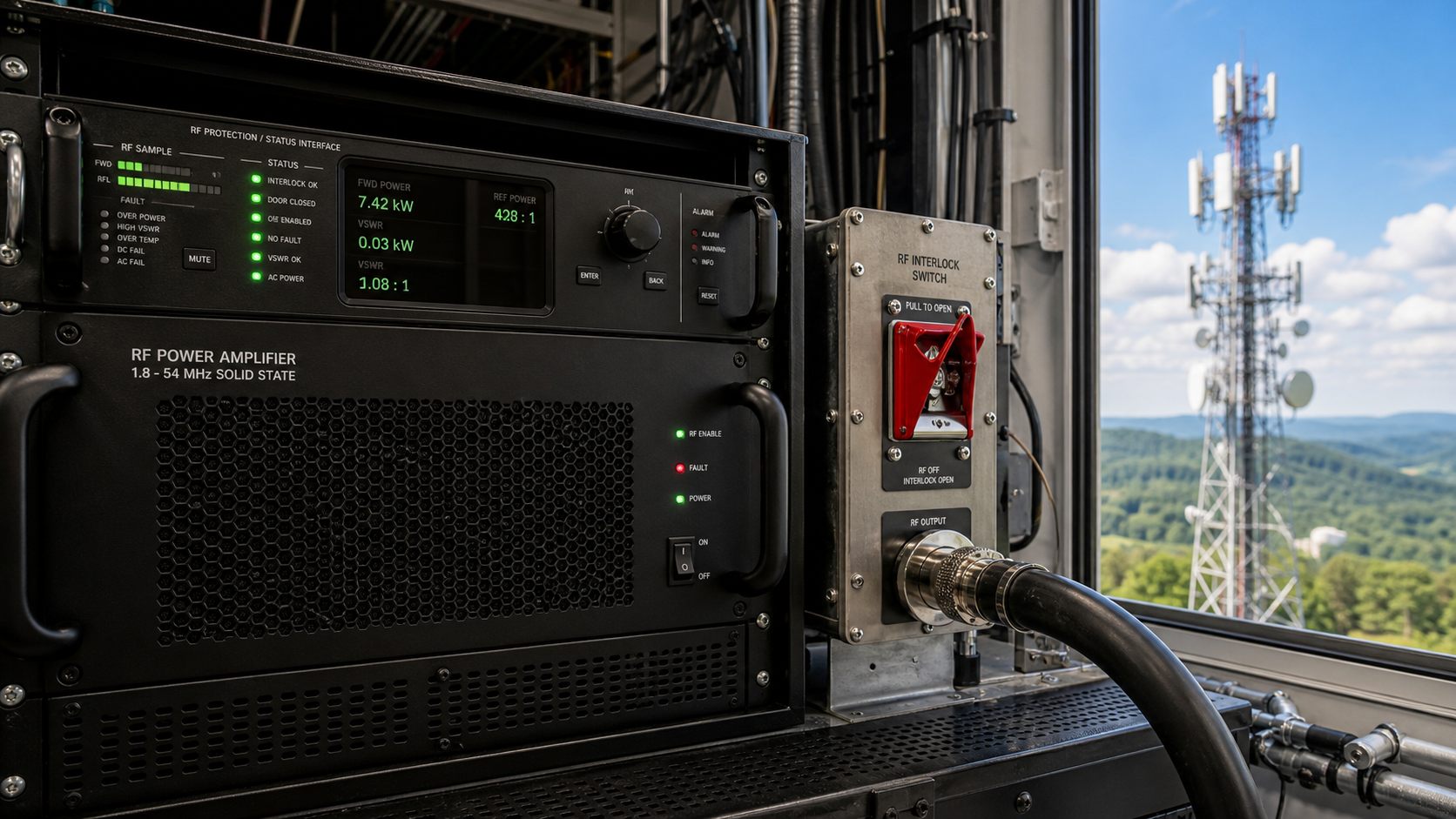
RF PA enable logic is easy to oversimplify: the controller sends Enable, the PA reports enabled, and the system assumes RF output is now under control. But those events do not prove the same thing. Output may still be blocked by protection, routed through an unconfirmed RF path, resume after reset, or appear while the controller is reading stale feedback.
The real integration boundary is not whether an enable command exists. It is whether the system can prove when RF output is permitted, when it must remain inhibited, and which state becomes authoritative during startup, reboot, communication loss, path switching, and fault recovery.
Before accepting the control design, what evidence proves that “PA enabled” cannot be mistaken for “RF output allowed”?
1. What Does RF PA Enable Logic Actually Control?
An RF PA enable signal should be treated as one input to the output-permission decision, not as proof that RF transmission is already valid.
A practical system may contain several different states:
- enable command sent
- enable command accepted
- PA enabled
- RF output allowed
- RF output active
- system ready
Those states can occur at different times and may depend on different conditions.
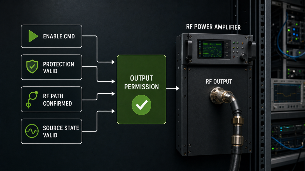
For example, a controller may successfully send the enable command while the PA remains inhibited because:
- protection is active
- protection feedback is not yet valid
- the intended RF path is not confirmed
- source drive is not in the expected state
- a reset or recovery sequence is incomplete
- the controller is still using stale feedback
- the system has not yet reached the project-defined ready condition
The distinction matters because an operator interface that shows only PA Enabled can create false confidence. It may confirm one control action while saying nothing about whether RF output is permitted at that moment.
A protection-clear indication should be used for output-permission logic only after the relevant monitoring interface and RF PA protection logic state definition are valid. An early, stale, or default response should not authorize RF output.
The same rule applies to RF PA status feedback. A reported state is useful only when the controller knows where the information came from, when it was refreshed, and whether it corresponds to the intended PA or channel.
Where the enable state is delivered through GPIO, UART, RS485, or another remote-control method, the RF PA control interface must also define how commands, states, and fault conditions are represented.
Enable State vs Output Permission
| State | What It Confirms | What It Does Not Prove |
|---|---|---|
| Enable command sent | Controller issued a request | PA accepted the request |
| Enable command accepted | Interface acknowledged the command | RF output is allowed |
| PA enabled | PA entered the defined enable state | Protection, RF path, or source conditions are valid |
| RF output allowed | Project-defined permission conditions are satisfied | RF output is already present |
| RF output active | RF is detected at the defined reference point | Complete system-ready conditions are satisfied |
| System ready | Required project conditions are satisfied according to defined logic | Any condition not included in that logic |
The important engineering question is therefore not:
“Did Enable go high?”
It is:
“What conditions must be true before RF output is allowed?”
2. Where Can Unexpected RF Output Come From?
“Unexpected RF output” should not be used as a generic fault description.
The first step is to define when the RF appeared and where it was observed.
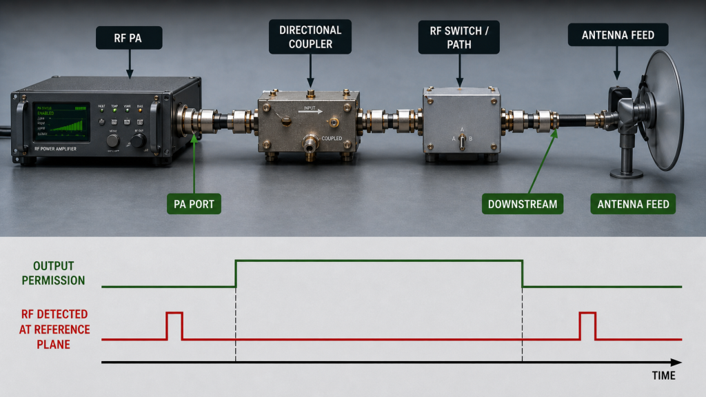
Unexpected RF may mean:
- RF appeared before output permission was valid
- RF remained present after disable
- RF returned after controller reset
- RF appeared after communication loss
- output appeared on the wrong PA or channel
- RF appeared while the intended path was not confirmed
- RF was detected at the PA port but not expected at the antenna path
- stale status indicated disabled while RF was still present
- RF restarted automatically after a protection or reset event
These are different failure modes and should not be diagnosed from the same single status bit.
The RF reference point also matters.
“Output active” could refer to:
- PA output connector
- directional-coupler indication
- detector output
- downstream RF path
- antenna-feed point
- antenna-end power
A control log that says PA enabled cannot by itself prove what happened at any of those RF reference planes.
For troubleshooting, define unexpected RF output by both time and reference plane: PA-port output, downstream indication, antenna-end power, wrong-channel output, or RF appearing outside the permitted state.
This prevents the control problem from being mixed with feeder loss, RF switching, channel mapping, or downstream path behavior.
3. What Must Default and Fail-Safe States Define?
Enable logic becomes most important during transitions rather than steady operation.
A system may behave correctly after everything is initialized but still produce an unsafe or ambiguous state during:
- power-up
- controller reboot
- communication loss
- watchdog reset
- PA reset
- protection trip
- protection recovery
- RF path change
- firmware restart
- shutdown
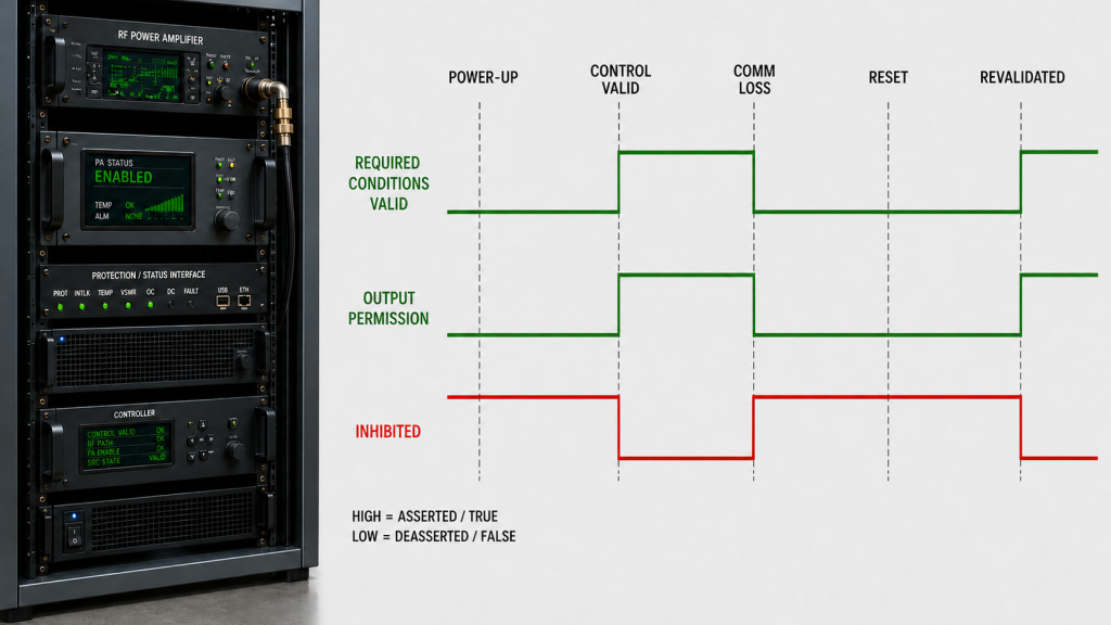
The RFQ should define the default output state explicitly and, unless the approved architecture requires another controlled condition, keep RF output inhibited until the required permission states are valid. It should also define what happens during controller boot, communication loss, reset, and recovery.
That does not mean every architecture must use the same electrical polarity or control implementation.
An enable input may be:
- active high
- active low
- GPIO-controlled
- command-controlled
- combined with hardware interlock
- combined with protection logic
- dependent on multiple controller states
The requirement is that the permitted and inhibited conditions are explicit.
Output permission should also be revoked when any required permission condition becomes invalid. The design should define which events remove permission, the maximum allowed inhibit-response time where timing matters, and which conditions must be revalidated before RF output can be allowed again.
Transition State vs Required Output Control
| Transition | Required Control Question | Evidence to Verify |
|---|---|---|
| Initial power-up | Is RF output inhibited before control states are valid? | Cold-start state and RF trace |
| Controller boot | Can boot-time defaults accidentally permit output? | GPIO / command-state log |
| Communication loss | Does loss of control remove output permission as required? | Communication-loss test |
| Watchdog reset | Can output resume before state revalidation? | Reset timeline |
| Protection trip | Is RF output inhibited within the required response window? | Protection and RF evidence |
| Protection recovery | Is re-enable automatic or explicitly authorized after revalidation? | Recovery-state log |
| RF path change | Is output permission removed until the intended path is valid again? | Path and RF timestamps |
| Shutdown | Does disable occur before the system loses authoritative control? | Shutdown timeline |
A reset is especially important.
Resetting an alarm, controller, or PA should not automatically be assumed to mean that RF output may resume. The system should define which states must be checked again before output permission is restored.
The same principle applies when a previously valid permission condition is lost. If protection becomes active, communication validity is lost, the selected RF path changes, or another required state becomes invalid, the control logic should define whether output permission is removed immediately or within a specified response window.
In remote or high-security installations, this distinction becomes more important because an operator may have no direct physical view of the equipment. The interface must distinguish powered, enabled, inhibited, faulted, and output active rather than collapsing them into one ON/OFF indication.
4. How Should Enable Logic Interact with SDR Drive and RF Path?
Enable logic does not operate in isolation.
The system may also depend on:
- SDR initialization
- SDR RF-output state
- input-drive level
- RF switch or path selection
- antenna-path condition
- PA protection status
- channel selection
- controller-ready state
However, there is no single universal rule that says SDR drive must always appear before PA enable or always after it.
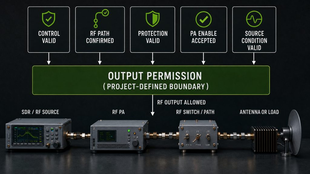
Some architectures may allow RF drive to exist while the PA remains safely inhibited. Others may keep SDR output disabled until the path, protection, and PA enable conditions are valid.
What must be verified is the project-defined output-permission boundary.
For example, a design could require:
- controller communication valid
- intended RF path confirmed
- relevant protection feedback valid
- PA enable accepted
- source-drive condition valid
- RF output permitted
- RF output verified
Another architecture could use a different order while remaining completely valid.
That broader DC-to-controller-to-SDR-to-PA relationship belongs in the C-UAS RF power-on sequence review. Enable logic should focus specifically on the condition that changes RF output from inhibited to allowed.
The SDR programmed output also should not be confused with the actual RF reaching the PA input. Where input drive is part of the enable decision or acceptance evidence, define the RF PA input power reference boundary rather than relying only on a source setting.
5. How to Diagnose Unexpected RF Output from Enable Logic
Start with evidence before changing polarity, firmware, timing, protection thresholds, or PA hardware.
A practical diagnostic sequence is:
- Define exactly where the unexpected RF was measured.
- Define when it appeared relative to the intended output-permission state.
- Identify the actual electrical or command enable polarity.
- Confirm the controller’s commanded enable state.
- Confirm the PA-reported enable state.
- Check whether protection feedback was valid at that moment.
- Check whether the intended RF path and channel were confirmed.
- Review SDR drive state.
- Check reset, watchdog, retry, and recovery events.
- Verify whether controller status was fresh or stale.
- Compare RF output with the control timeline.
- Confirm which condition should have granted or revoked output permission at that moment.
- Repeat the test during cold start, restart, communication loss, and required fault recovery.
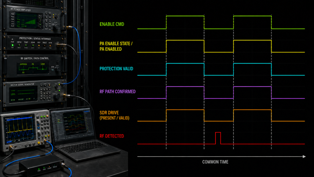
If enable events, controller states, and RF measurements come from different devices or logs, their timestamps should use a common trigger or verified time alignment before drawing a sequencing conclusion. Otherwise, logging latency or clock offset can be mistaken for an enable-logic fault.
Do not assume that a polarity problem is the root cause simply because RF appeared at the wrong time.
Unexpected RF can also come from:
- incorrect channel mapping
- stale feedback
- output path not matching controller state
- reset behavior
- protection recovery
- firmware default state
- external RF switching
- SDR behavior
- measurement interpretation
The sequence evidence should first identify which state failed, became valid late, was revoked late, or was interpreted incorrectly. Root cause should be assigned only after the relevant control, RF-path, protection, source, and measurement evidence is checked.
6. What Evidence Proves RF PA Enable Logic Is Controlled?
A successful one-time ON/OFF test is not enough.
Enable logic should be verified across the transitions that can grant, maintain, remove, and restore output permission.
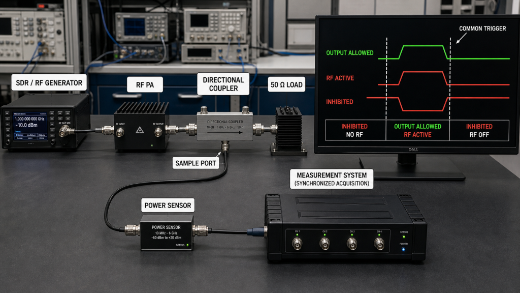
Useful evidence includes:
- enable command timestamp
- command acknowledgement where applicable
- PA enable-state feedback
- protection-state validity
- RF output start and stop time
- defined RF reference plane
- SDR output state
- relevant PA-input condition
- RF-path or channel state
- controller reboot behavior
- communication-loss behavior
- watchdog/reset behavior
- protection-trip behavior
- permission-revocation timing
- recovery behavior
- cold-start result
- restart result
- feedback refresh timing
- firmware or control-software version
- PA or channel identifier
- S/N-linked record where per-unit traceability is required
The most important evidence should show that:
RF output is absent when the system requires inhibition, becomes permissible only after the defined output-permission conditions are satisfied, and returns to the inhibited state when any required permission condition is removed.
Where response time is an acceptance parameter, the control and RF records should also prove that output was removed within the specified inhibit-response window.
This requires both control evidence and RF evidence.
A GPIO transition alone is not enough.
A software screen alone is not enough.
A PA status reply alone is not enough.
And an RF screenshot without the corresponding controller state does not prove the control logic.
Where multiple instruments or devices generate evidence, record how their timestamps were aligned and whether the timing uncertainty is small enough to support the conclusion.
For the broader relationship between enable permission, alarm interpretation, reset, feedback, and recovery, keep the project-level RF Power Amplifier control logic definition separate from this enable-specific acceptance test.
7. What Should an RF PA Enable Logic RFQ Define?
Terms such as remote control, PA enable, or fail-safe control are too vague for integration acceptance.
The RFQ should define exactly what the system expects the PA and controller to do.
Enable Logic RFQ & Acceptance Evidence
| RFQ Item | What Should Be Defined | Acceptance Evidence |
|---|---|---|
| Enable interface | GPIO, UART, RS485, or other approved control method | Interface definition |
| Enable polarity | Active-high, active-low, or command state | Logic / protocol record |
| Default state | Required output behavior before valid control is established | Cold-start test |
| Output permission | Conditions required before RF may be allowed | State-definition record |
| Permission revocation | Conditions that remove RF output permission, required inhibit-response time, and revalidation before re-enable | Synchronized control and RF shutdown trace |
| Protection validity | When protection status becomes authoritative | Timestamped status log |
| Communication loss | Required output behavior if control is lost | Communication-loss test |
| Controller reboot | Output behavior during boot and recovery | Reboot timeline |
| Reset behavior | Whether reset restores output automatically or requires revalidation | Reset test |
| SDR-drive interaction | Whether RF drive may exist while PA is inhibited | SDR / PA state evidence |
| RF-path state | Whether path confirmation is required before output permission | Path-state log |
| RF output evidence | Where RF presence or absence is verified | Defined RF reference-plane measurement |
| Feedback freshness | Maximum acceptable age or refresh condition where required | Status timestamps |
| Timing evidence | Required time alignment between control and RF records | Synchronized timeline |
| Fault recovery | Conditions required before output can resume | Recovery record |
| Traceability | Firmware version, channel, module, or S/N where required | Acceptance report |
When comparing RF Power Amplifier Modules for SDR or C-UAS integration, do not ask only whether the module provides an enable pin or remote-control command.
Ask what Enable actually permits, what removes that permission, what state is used when control is unavailable, how protection and reset interact with output permission, and what evidence can prove that RF remained inhibited when required.
FAQ
Does PA enabled mean RF output is allowed?
Not necessarily. PA enabled confirms one defined PA or controller state. RF output permission may still depend on protection validity, RF-path selection, source condition, reset state, or other project-defined requirements.
Should an alarm reset automatically restore RF output?
Only if the approved control architecture explicitly defines that behavior and all required output-permission conditions are revalidated. A reset should not be assumed to authorize RF output merely because an alarm has cleared.
What evidence proves RF PA enable logic is fail-safe?
Use synchronized control and RF evidence to verify that output remains inhibited when required, becomes permissible only after the defined conditions are satisfied, and returns to the inhibited state when a required permission condition is lost. Where response time matters, verify the inhibit transition against the specified timing limit.
Conclusion
RF PA enable logic is controlled only when the system can distinguish enabled from RF output allowed and prove that distinction during both normal operation and transition states.
An enable command, acknowledgement, or PA-enabled flag is not enough by itself. Output permission should depend on the project-defined state logic, including valid protection feedback, the required RF path and source conditions, reset or recovery state, and any other conditions required by the system architecture. If one of those required conditions becomes invalid, the control logic should also define how permission is removed and what must be revalidated before RF output can resume.
The highest-risk cases are usually not steady-state operation but startup, reboot, communication loss, reset, protection recovery, and path changes. Those transitions should be tested with synchronized control and RF evidence so that a stale status value, logging delay, or default state is not mistaken for correct enable behavior.
For acceptance, define what output inhibited, PA enabled, RF output allowed, RF output active, and system ready mean before testing begins. Then verify that RF is absent when inhibition is required, appears only after the defined permission boundary is satisfied, and is removed within the required response window when that permission is revoked.
Contact RF SKYPOWER with your control interface, enable polarity, default and fail-safe requirements, SDR drive condition, RF-path state, protection feedback, permission-revocation rules, reset and recovery behavior, inhibit-response requirement, and required output-control evidence to review the RF PA integration before approval.