











RF PA status feedback can look complete on a wiring diagram and still be unusable in the final controller. A PA may provide an alarm pin, ready flag, temperature value, or serial status while the dashboard assigns the wrong channel, reverses the active state, displays stale data, or combines several different conditions into one “PA Fault” label.
The integration risk is not simply missing feedback. It is trusting a feedback value before its source, electrical or protocol representation, module identity, state meaning, freshness rule, and controller action boundary are defined. In a multi-module RF cabinet, one mapping error can send engineers to the wrong PA even when the original module signal is correct.
Before accepting the feedback design, what evidence proves that the controller is showing the right state for the right PA—and that the value is still valid when the decision is made?
1. What Must RF PA Status Feedback Mapping Define?
Status feedback mapping should connect each physical or protocol-level PA feedback source to an unambiguous controller-visible value or state meaning, together with the correct module or channel identity.
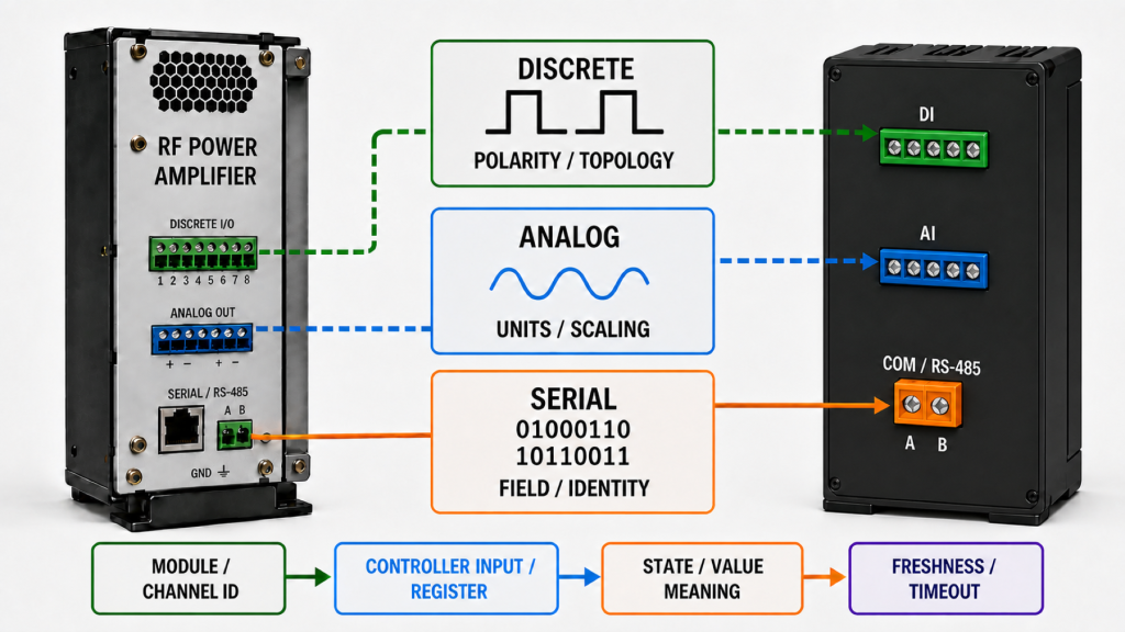
A usable map should identify:
- PA or module identity
- physical slot or cabinet position
- frequency band or RF channel
- signal source
- feedback representation
- controller input, register, or field
- asserted and cleared state where applicable
- units and scaling where applicable
- update or polling rule
- invalid or timeout behavior
- displayed value or state name
- logging requirement
- firmware or protocol revision
The feedback representation must also be classified correctly.
For discrete feedback, define:
- active-high or active-low polarity
- valid voltage thresholds
- electrical topology
- pull-up or pull-down requirement where applicable
- push-pull, open-drain, or open-collector behavior
- default or invalid state
For analog feedback, define:
- measured quantity
- units
- scaling
- valid operating range
- out-of-range behavior
- update or filtering rule
For serial feedback, define:
- register, field, or message
- bit meaning
- device or channel identity
- value definition
- update or polling interval
- invalid or timeout behavior
- firmware or protocol version
These categories should not be mixed. Active-high and active-low describe logic assertion. Open-drain describes electrical output topology. Analog feedback requires units and scaling. Serial feedback requires protocol, field, identity, and validity definitions.
Where feedback is transferred through GPIO, UART, RS485, or another remote-control method, the RF PA control interface should define how those electrical or protocol values and states reach the controller.
Feedback Representation vs Mapping Requirement
| Representation | What Must Be Defined | Common Mapping Risk |
|---|---|---|
| Discrete | Polarity, threshold, topology, default state | Active state reversed or floating input misread |
| Analog | Quantity, units, scaling, valid range | Correct signal assigned to the wrong engineering value |
| Serial | Register/field, identity, update rule, timeout behavior | Wrong module, stale register, or incorrect field interpretation |
A feedback source can therefore be electrically or digitally present and still be mapped incorrectly.
2. Why Can a Valid Signal Still Create the Wrong Controller State?
The controller does not see “truth.” It sees the value or state created by the mapping between the PA feedback source and the software interpretation.
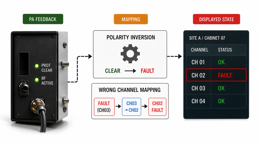
The original PA signal may be correct while the system still reports the wrong condition because:
- active-high is interpreted as active-low
- one module is assigned to another channel
- a serial address is mapped to the wrong PA
- a latched alarm is displayed as a current alarm
- a stale value remains on screen after communication loss
- one general fault label hides several independent causes
- an analog value uses the wrong scaling
- a firmware or protocol revision changes a register or field definition
- the dashboard name does not match the physical module position
This creates two separate troubleshooting questions:
- Did the PA report the correct value or state?
- Did the controller interpret and display it correctly?
Those questions should be separated before replacing hardware or changing alarm thresholds.
A correctly mapped status proves that the controller interpreted the reported value or state correctly. It does not by itself prove sensor accuracy, alarm-threshold accuracy, or the underlying RF performance.
For example, correctly displaying VSWR Alarm = Active proves that the controller received and interpreted the reported alarm state. It does not prove the actual VSWR value, sensing-point accuracy, threshold calibration, or complete protection response.
Those deeper conditions belong in the RF PA protection logic verification.
3. Which RF PA States Must Be Kept Separate?
One of the most common mapping errors is collapsing different PA or system states into one broad label such as ON, READY, or FAULT.
The map should also distinguish native PA feedback from controller-derived or system-derived states. A PA may directly report an enable state, alarm bit, temperature value, or supply condition, while communication lost, RF output stable, or system ready may be calculated by the controller from several inputs. The acceptance record should identify that provenance explicitly.
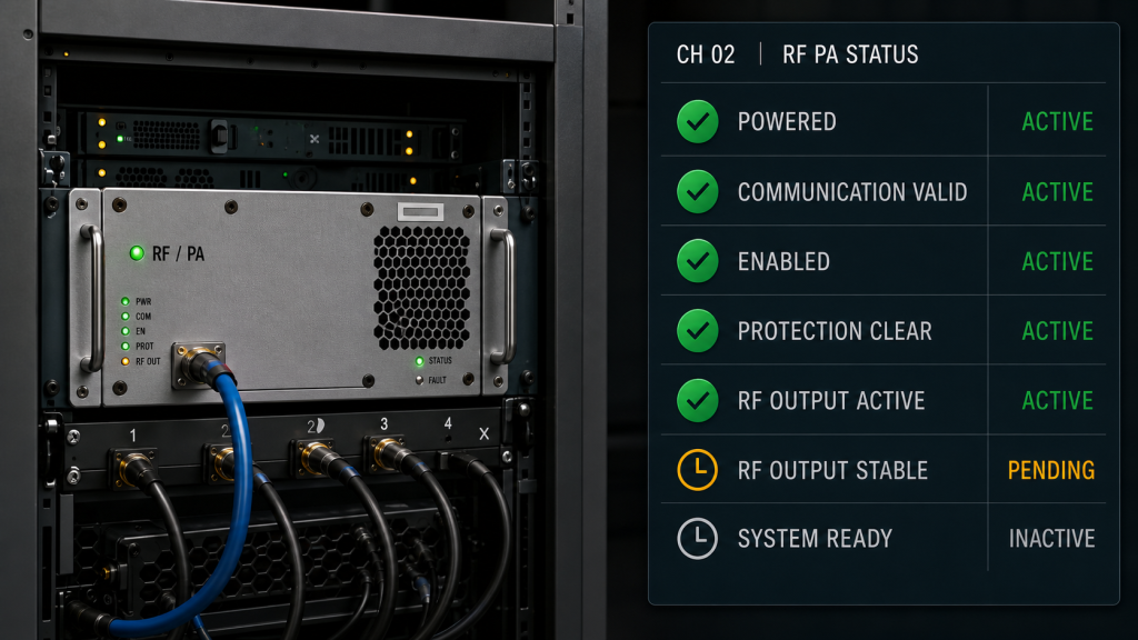
Possible controller-visible states include:
- powered
- communication valid
- enabled
- protection clear
- protection active
- RF input condition valid
- RF output active
- RF output stable
- communication lost
- system ready
These states are not interchangeable, and their source may differ by architecture.
An Enabled state should prove only the enable condition defined for that interface. It should not be extended into RF output permission, RF presence, or stable RF performance unless those meanings are explicitly part of the approved state definition.
The better check is simple: do not treat PA enabled as RF output stable.
Likewise:
Powereddoes not proveEnabled.Protection cleardoes not prove RF output is present.RF output activedoes not prove system readiness.Communication validdoes not prove the value is fresh enough for the current decision.System readyshould not be presented as native PA feedback unless the PA actually provides that defined state.
Controller State vs What It Actually Proves
| Controller State | Typical Source | What It Can Prove | What It Does Not Prove |
|---|---|---|---|
| Powered | PA feedback or monitored supply state | Defined PA power condition is present | PA is enabled or producing RF |
| Enabled | PA or controller enable feedback | PA entered the defined enable state | RF output permission or stable RF output |
| Protection clear | PA protection feedback | No blocking protection state is reported at that valid monitoring point | Sensor accuracy or RF performance |
| RF output active | PA detector or external RF measurement | RF is detected at the defined reference point | Stable output or system readiness |
| RF output stable | Usually controller-derived from defined measurement criteria | Output meets the defined stability condition | Antenna-end power unless that is the defined reference plane |
| Communication lost | Controller-derived | Controller no longer has valid communication | Last-known PA value is still current |
| System ready | Controller or system-derived | Project-defined readiness conditions are satisfied | Any condition outside that readiness definition |
Typical Source is not universal. The actual source and derivation rule must be defined for the specific PA and controller architecture.
4. How Do Multi-Module RF Cabinets Create Mapping Errors?
Status mapping becomes more difficult when one controller manages several PAs, frequency bands, RF paths, or cabinet positions.
A useful mapping chain may need to connect:
PA S/N → cabinet slot → frequency band → RF channel → harness or bus address → controller input/register → dashboard name → logged event
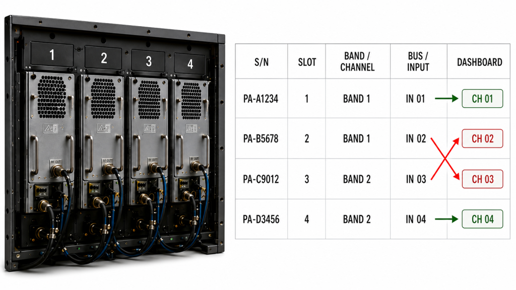
If any link is wrong, the displayed alarm may point to the wrong hardware.
Common causes include:
- identical modules installed in different slots
- repeated wiring harnesses
- copied controller configuration
- changed serial addresses
- module replacement without map revision
- swapped channel names
- frequency-band labels that no longer match the installed PA
For that reason, a multi-module map should not rely only on generic names such as PA1, PA2, Channel A, or Channel B.
Where practical, the acceptance record should identify:
- module S/N
- physical slot
- frequency band
- controller address or input
- firmware or protocol version
This makes the feedback chain traceable when a module is replaced or a cabinet is serviced remotely.
The same principle applies in rooftop, venue, border, vehicle, or other remote C-UAS installations: the operator should be able to identify which physical PA created the reported value or state without guessing from a generic dashboard alarm.
5. How to Trace an RF PA Status Mapping Error
Start at the original PA feedback source and move toward the final controller-visible value or state.
A practical troubleshooting sequence is:
- Identify the physical PA, S/N, slot, channel, and frequency band.
- Confirm the original PA feedback source.
- Identify whether the feedback is discrete, analog, or serial.
- Verify polarity, topology, scaling, register, field, or protocol definition.
- Confirm the harness, GPIO input, bus address, or communication path.
- Check the controller mapping and module/channel assignment.
- Determine whether the displayed item is native PA feedback or a derived state; if derived, verify its source inputs and logic.
- Confirm the displayed value or state name and whether it is current.
- Trigger or simulate the relevant condition where safe and appropriate.
- Verify the correct module/channel response and event log.
- Repeat for communication loss, reset, restart, and other required conditions.
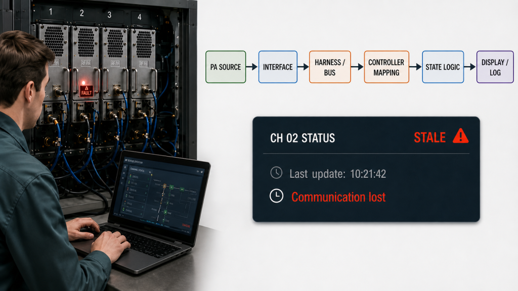
Each controller-visible value or state should define how freshness is determined and what happens when its maximum valid age or communication timeout is exceeded.
Freshness may use an event timestamp, polling interval, maximum allowed age, heartbeat, sequence counter, or another project-defined validity rule.
A last-known value should not remain visually equivalent to a confirmed current value after communication validity is lost. If Protection Clear was the last valid state before communication loss, the controller should distinguish that stale or last-known value from confirmed live feedback.
When feedback logs are compared with controller commands, RF measurements, protection events, or startup events from other devices, use a shared time base or verified timestamp alignment before drawing a sequencing conclusion.
If the problem is specifically command response, polling completion, timeout, or response ordering, review the AT command timing separately rather than treating every delayed status as a mapping error.
6. What Evidence Proves the Feedback Map Is Correct?
A wiring diagram alone does not prove that status feedback works correctly in the integrated system.
The evidence should verify the complete path:
physical PA condition → feedback source → electrical/protocol representation → controller mapping → native or derived state logic → displayed value/state → event log
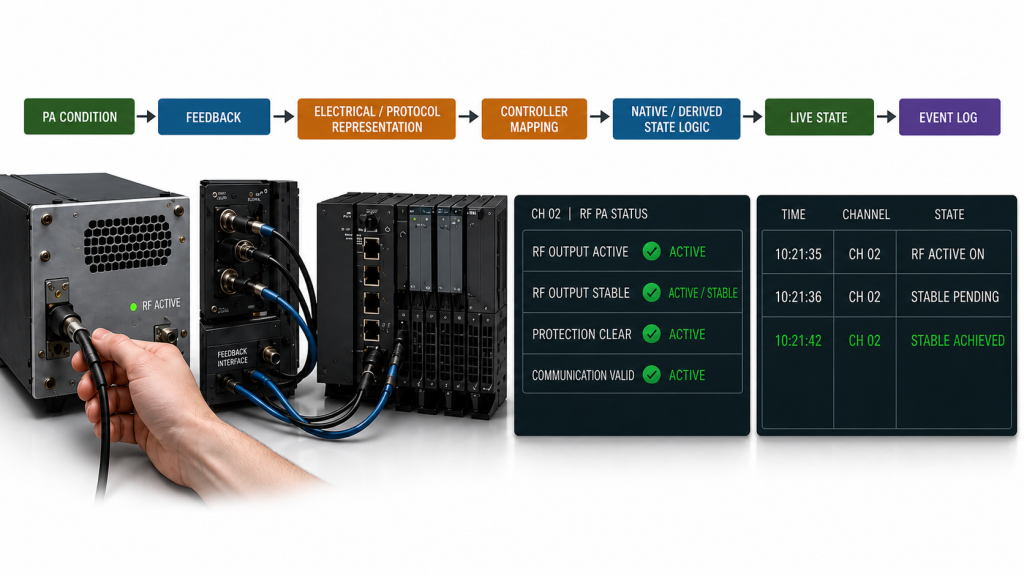
For derived states, record which source signals or measurements create the state and which condition invalidates it.
Useful acceptance evidence includes:
- module S/N, slot, band, and channel
- feedback source and representation
- native or derived state classification
- derivation rule where applicable
- polarity, topology, analog scaling, or serial field definition
- controller input or address
- displayed value or state name
- asserted, cleared, or latched behavior where applicable
- update or polling interval
- freshness and communication-loss rules
- reset or restart behavior
- timestamped event log
- firmware or protocol version
- map revision
For an alarm or other discrete state, verify that the intended PA generated the expected feedback, the controller mapped it to the correct module and label, the event was logged, and the state cleared or latched according to its definition.
For a derived state, verify the required source inputs, their current validity, the derivation rule, and the condition that removes or invalidates the state.
Correct mapping proves that the controller interpreted the PA-reported value or state correctly. For derived states, it proves that the approved derivation logic was applied to the defined source inputs.
It does not automatically prove:
- sensor calibration
- alarm-threshold accuracy
- RF output performance
- VSWR measurement accuracy
- protection-response time
- complete system readiness outside the defined state logic
For the broader relationship between status, enable, alarm, reset, communication, and system action, keep the project-level RF Power Amplifier control logic separate from this feedback-mapping acceptance test.
7. What Should an RF PA Status Feedback RFQ Define?
Terms such as alarm output, status pin, remote monitoring, or serial feedback are not sufficient RFQ definitions.
The RFQ should identify what each feedback value or state means and how it will be verified after integration.
RF PA Status Feedback RFQ & Acceptance Evidence
| RFQ Item | What Should Be Defined | Acceptance Evidence |
|---|---|---|
| Feedback states / values | Required powered, enabled, alarm, ready, measured, output, or other information | Approved feedback list |
| Signal representation | Discrete, analog, or serial | Interface definition |
| Polarity / topology | Active state, thresholds, open-drain/push-pull requirements where applicable | Electrical test |
| Analog scaling | Quantity, units, scaling, valid range | Measured-value comparison |
| Serial definition | Register/field, bit meaning, address/channel identity | Protocol record |
| Module identity | S/N, slot, band, or channel association | Mapping record |
| State provenance | Whether each value/state is native PA feedback or derived, and the derivation rule where applicable | Approved mapping and state-logic record |
| State meaning | Exact condition represented by each state | Approved state definition |
| Freshness | Polling interval, maximum age, heartbeat, or timeout rule | Timestamped status record |
| Communication loss | Controller behavior when feedback is no longer valid | Communication-loss test |
| Latched states | Clear/reset behavior where applicable | Reset test |
| Dashboard mapping | Displayed label/value and module/channel identity | UI verification |
| Event logging | Required timestamp and value/state record | Event log |
| Firmware / protocol | Version used for acceptance | Version-controlled report |
| Traceability | Map revision and module identity | Acceptance report |
When comparing RF Power Amplifier Modules for a multi-module or remotely controlled system, ask more than whether alarm or status feedback exists.
Define at minimum:
- which values and states are available;
- which are native and which are controller-derived;
- how the correct PA or channel is identified;
- when each value becomes stale or invalid;
- what evidence will be supplied for integration acceptance.
FAQ
Can one general fault signal represent all PA alarms?
It can be used as a summary indication if that is sufficient for the approved system architecture, but it should not replace individual fault identification when operators or service engineers need to distinguish temperature, VSWR, supply, or other protection conditions.
How do I know whether a PA Ready status is trustworthy?
Define what creates the Ready state, whether it is native or controller-derived, which PA or channel it belongs to, how freshness is determined, and what happens after communication loss or timeout. A visible Ready label without those definitions is weak acceptance evidence.
What evidence proves an RF PA status feedback map is correct?
Verify the complete path from the physical PA condition through the feedback representation, controller mapping, module/channel identity, native or derived state logic, dashboard display, and event log. Also verify stale, communication-loss, reset, and required restart conditions.
Conclusion
An RF PA status feedback map is valid only when the controller can trace each displayed value or state to the correct source, representation, module or channel identity, engineering meaning, provenance, and current validity.
A visible alarm, Ready flag, temperature value, or status bit is not enough. The controller must know which PA produced the feedback, whether the displayed result is native or derived, what it actually proves, and whether the value is still current. Correct mapping proves interpretation and derivation—not sensor calibration, RF performance, protection response, or conditions outside the defined logic.
For acceptance, verify the complete signal-to-dashboard chain, including identity, value/state definition, provenance, mapping, derivation where applicable, freshness, communication-loss behavior, reset behavior, and timestamped evidence. This traceability prevents a correct PA feedback signal from becoming a wrong maintenance or control decision.
Contact RF SKYPOWER with your required feedback states and values, interface type, module and channel mapping, native or derived state requirements, alarm definitions, polling or update rules, communication-loss behavior, firmware or protocol version, and acceptance-evidence requirements to review the RF PA integration before RFQ.