










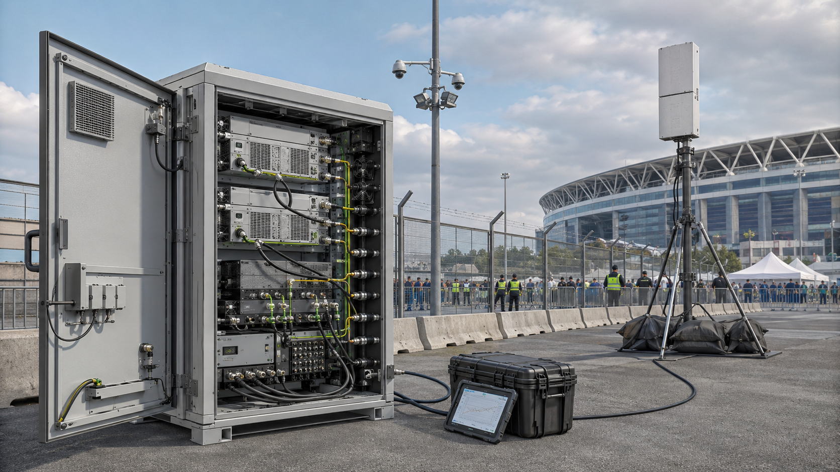
Cabinet RF routing can look correct while the active RF path is still wrong. Short internal jumpers, clear cable labels, and a clean cabinet layout do not prove that the intended PA is connected through the intended switch, filter, combiner, feedthrough, and cabinet output under the test condition being accepted.
The integration risk appears when route identity and route performance are treated as the same thing. A controller can show the correct channel name while the physical switch path is wrong, a dummy-load test can bypass part of the installed route, or two power readings can come from different RF reference planes and still be treated as if they describe the same output.
Before C-UAS PA acceptance, what evidence proves that the correct module is using the correct cabinet RF route—and that the measured result actually belongs to that route?
1. What Must a Cabinet RF Route Define?
For this article, the primary cabinet-routing boundary runs from the PA output connector through the installed internal RF components to the defined cabinet RF output or feedthrough.
Depending on the cabinet architecture, that internal path may include:
- RF jumpers
- switches
- filters
- combiners
- dividers
- directional couplers
- attenuators
- adapters
- bulkhead connectors
- cabinet feedthroughs
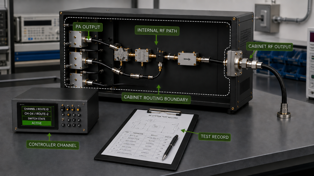
External feeder and antenna conditions are relevant when comparing the cabinet route with the complete installed path, but they should not be treated as part of the same acceptance boundary unless the test explicitly includes them.
A usable route definition should connect:
PA module → PA output connector → internal RF components → cabinet RF output → controller route identity → test record
For multi-module systems, the route should also identify:
- module S/N
- frequency band
- physical cabinet slot
- switch or filter path
- controller channel
- cabinet output connector
- test reference plane
A correct route map proves identity and traceability. It does not by itself prove insertion loss, return loss, VSWR, power handling, or full-power behavior.
That distinction matters because a cabinet can be wired exactly according to the drawing and still fail RF acceptance because:
- a connector is damaged
- a jumper is compressed
- the wrong switch state is active
- a filter is assigned to the wrong band
- an internal transition introduces excess mismatch
- the test result belongs to another reference plane
Short cable also does not automatically mean verified routing. Tight bends, connector strain, cable compression, and enclosure closure can still change the final installed condition. Detailed RF cable bending checks should remain separate from the route-identity decision.
Cabinet RF Route Boundary and Identity
| Route Item | What Must Match | Acceptance Evidence |
|---|---|---|
| PA module | S/N, band, physical slot | Module record |
| PA output | Correct physical connector | Route map / inspection |
| Internal RF path | Jumper, switch, filter, combiner, coupler | Drawing + installed-route verification |
| Cabinet output | Correct feedthrough or connector | Label + physical route record |
| Controller route | Channel and switch state | Controller configuration |
| Test point | Defined RF reference plane | Acceptance record |
For cabinets where path separation or cable-entry coupling becomes part of the failure mechanism, keep the dedicated RF PA shielding review separate from the basic routing map.
2. How to Isolate Route-Related VSWR and Output Problems
A VSWR alarm, high reflected power, or lower-than-expected cabinet output does not automatically prove that the PA itself is defective.
The first question should be:
Which physical route was active when the symptom appeared?
Then define where the measurement was made.
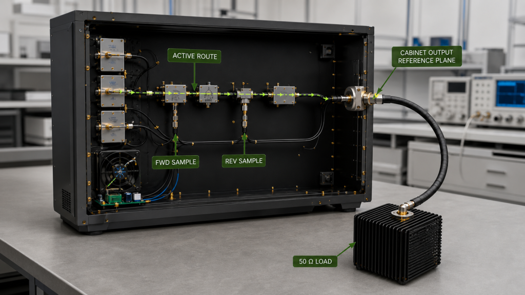
Possible RF reference planes include:
- PA output connector
- internal coupler
- cabinet RF output
- dummy-load connection
- another approved test point
Before comparing output or loss, define the RF reference plane and the active switch or filter state used for the measurement.
A reading at the PA output connector and a reading at the cabinet output should not be treated as the same Pout. If the difference is used to determine route loss, the source operating state, frequency, active route, load condition, and measurement corrections should be kept comparable and documented.
That means the comparison may also need to account for:
- cable or adapter correction
- attenuator or coupler correction
- instrument reference plane
- switch or filter state
- PA output condition
- input drive
- DC supply condition
- thermal state where relevant
A practical isolation sequence is:
- Confirm the correct PA and frequency band.
- Confirm the intended switch, filter, combiner, or route state.
- Verify the physical connector and route identity.
- Inspect required terminations and alternate paths.
- Perform passive or controlled low-power route checks where applicable.
- Compare route behavior at the defined frequency and reference plane.
- Move to controlled high-power verification only after the route is confirmed.
- Repeat the test in the final installed cabinet condition.
An unused or alternate port matters only when the energized RF network exposes that port and the architecture requires a defined termination.
For example, an open spare connector that is completely isolated from the active RF network does not become a reflected-power cause simply because it is open. A port connected through an active combiner, divider, switch state, or coupled network may be different and should be checked against the approved architecture.
Do not disconnect, move, tighten, or reroute high-power RF cables while RF output is active. Disable RF and place the system in the approved safe state before changing the physical route.
Route Symptom vs Isolation Check
| Symptom | Do Not Assume | First Route Check |
|---|---|---|
| One route shows high reflected power | PA is defective | Active switch path, connector, termination |
| PA passes direct load but cabinet path fails | Antenna is automatically at fault | Identify which cabinet elements were bypassed |
| One band shows lower cabinet output | PA has poor band-edge performance | Filter, switch, transition, reference plane |
| Controller label disagrees with observed RF path | Firmware is necessarily wrong | Physical route and channel assignment |
| Result changes after cabinet closure | PA became unstable | Cable position, connector strain, route condition |
The goal is to identify the failed boundary before assigning root cause.
3. Which Internal RF Paths Must Be Separated?
Multi-band C-UAS cabinets often place several RF paths in a small mechanical volume.
That makes route separation important for both traceability and repeatability.
Paths may need to distinguish:
- different PA frequency bands
- transmit and monitoring paths
- forward and reflected-power sensing
- switched outputs
- combined and uncombined paths
- high-power and low-level RF lines
- control or digital wiring near RF cables
A clean layout alone does not prove sufficient separation.
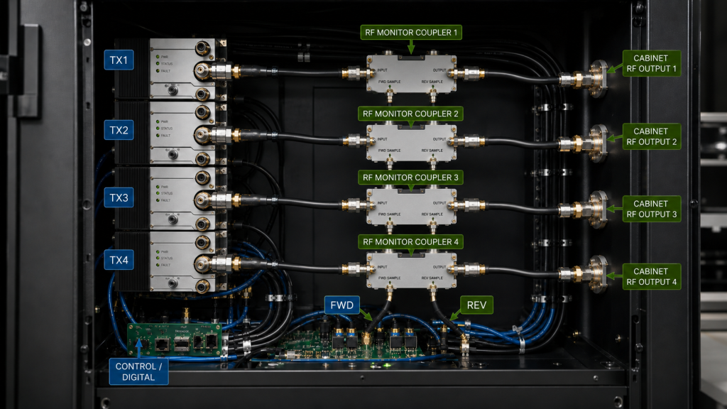
The route record should show:
- which PA feeds which path
- where switching occurs
- where filtering occurs
- which cabinet connector belongs to each band
- whether any internal coupler or detector changes the test boundary
- which path was active during acceptance
If route behavior changes when adjacent channels operate, the next question should be whether the problem comes from routing, shielding, grounding, switching, or another coupling path.
Do not automatically label every cross-channel symptom as an RF routing fault.
The requirement for this page is narrower:
the intended RF path must be identifiable and reproducible before its RF behavior can be judged.
4. How Do Multi-Module Cabinets Keep Route Identity Correct?
Route identity becomes harder to maintain when several similar PA modules are installed in one cabinet.
A useful traceability chain may look like:
PA S/N → cabinet slot → frequency band → controller channel → switch/filter path → cabinet output connector
If any link is wrong, engineers may test the correct hardware through the wrong path or assign a valid test result to the wrong module.
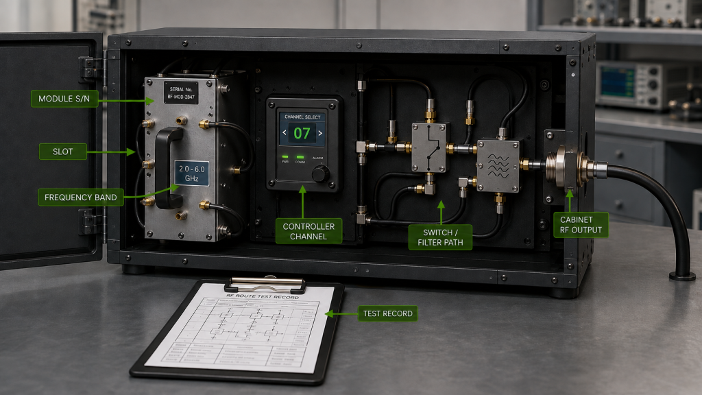
Common causes include:
- identical modules installed in adjacent slots
- copied controller configuration
- swapped RF jumpers
- filter labels that no longer match the installed band
- module replacement without updating the route map
- changed switch assignments
- service work that moves cables but not documentation
For this reason, labels such as:
- PA1
- PA2
- RF OUT 1
- RF OUT 2
are not enough by themselves in a complex multi-band cabinet.
Where practical, the acceptance record should identify:
- module S/N
- frequency block
- slot
- switch/filter path
- cabinet output connector
- test record ID
For vehicle-mounted or multi-band cabinets where the relationship between frequency bands and installed modules becomes more complex, keep the detailed RF PA frequency-block map as a separate design record.
Transportable or frequently serviced cabinets need the same discipline. After module replacement, cable movement, or route reconfiguration, route labels and acceptance records should be checked again rather than assuming the previous map is still valid.
5. What Evidence Proves Cabinet RF Routing Before Acceptance?
Cabinet RF routing should not be accepted from a drawing, photograph, or one successful RF reading alone.
Acceptance should prove two different things:
Route Identity
The record should prove:
- the correct PA is installed
- the correct band is assigned
- the intended internal path is active
- the correct cabinet connector is used
- the controller route name matches the physical route
- the test record belongs to that exact configuration
Route-Specific RF Behavior
Where required by the project, the record should also prove RF behavior under a defined test condition, including:
- frequency
- switch or filter state
- load condition
- RF reference plane
- output or insertion-loss result
- forward / reflected indication where relevant
- cabinet state
- PA/source operating condition
- test equipment or correction boundary where required
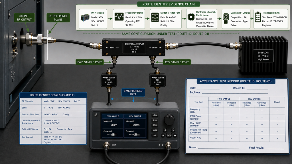
Where route performance is inferred from powered measurements at different reference planes, the test should also document a comparable PA/source condition. Otherwise, a change in PA output, input drive, supply condition, or thermal state can be mistaken for route loss.
If full-power or sustained-power routing behavior is part of acceptance, define the required output level, duty cycle or test duration, and thermal condition well enough to distinguish route behavior from PA output drift.
A route map that matches the hardware proves identity.
A power measurement proves performance only at its defined reference plane and test condition.
Neither one should be used as a substitute for the other.
For example:
- A PA-port test can prove PA output at the PA connector.
- A cabinet-output test can include the internal route.
- A dummy-load test may or may not include every installed cabinet element depending on where the load is connected.
- A full installed-path result may include losses and conditions outside the cabinet-routing boundary.
The acceptance report should make those differences visible rather than combining them into one generic RF output passed statement.
If a cabinet route is changed after acceptance, the affected route should be identified and retested to the extent required by the approved configuration-control process.
6. What Should a Cabinet RF Routing RFQ Define?
Statements such as:
short RF cableslow-loss routinggood VSWRclean cabinet layout
are not sufficient RFQ requirements.
The RFQ should define which route will be supplied and what evidence will be required to accept it.
Cabinet RF Routing RFQ & Acceptance Evidence
| RFQ Item | What Should Be Defined | Acceptance Evidence |
|---|---|---|
| Module identity | S/N, band, slot, or other required identifier | Module record |
| Route definition | PA output through internal RF path to cabinet output | Route drawing / map |
| Switching | Required switch states and route assignments | Controller + physical verification |
| Filters / combiners | Band and path assignment | Installed configuration record |
| Cabinet output | Exact feedthrough / output connector | Physical label + drawing |
| RF reference plane | PA port, cabinet output, or other approved point | Test procedure |
| Route loss | Required insertion loss or correction where applicable | Measured installed-route data or approved baseline plus project-defined verification |
| Return loss / VSWR | Requirement and test point where applicable | RF measurement |
| FWD / REV evidence | Coupler or detector location, relevant reference plane, and required interpretation where applicable | Logged FWD / REV record with defined monitoring point |
| Load condition | Dummy load or other approved load | Test record |
| Frequency | Required test frequencies or band coverage | Acceptance report |
| PA/source state | Required drive, output, supply, duty-cycle, or thermal condition where needed for comparison | Baseline or synchronized test record |
| Route identity | Module/channel/path traceability | Mapping record |
| Change control | What requires retest after route modification | Revision record |
| Final evidence | Required screenshots, logs, measurements, or report | Acceptance package |
When comparing RF Power Amplifier Modules for a C-UAS cabinet, routing questions should therefore go beyond PA output power.
Define:
- which PA feeds which cabinet route;
- which switch, filter, combiner, and connector belong to that route;
- where RF performance is measured;
- which PA/source condition must remain comparable;
- which conditions must be reproduced during acceptance;
- what evidence proves the result belongs to the installed route.
This prevents a valid PA test from being mistaken for proof of a route that was not actually included in the test.
FAQ
Can a short internal RF cable still cause a routing problem?
Yes. Cable length alone does not prove correct routing or good RF behavior. Connector strain, bend condition, switch or filter assignment, mechanical installation, and the defined RF reference plane can still affect the final route.
Can a PA pass a dummy-load test while the cabinet route still fails?
Yes, if the dummy-load setup bypasses part of the installed cabinet route. The test record should identify where the load was connected and which internal components were included before the result is used for cabinet-route acceptance.
What evidence proves cabinet RF routing is ready for acceptance?
The evidence should prove both route identity and route-specific RF behavior. That normally means the correct PA, band, switch/filter path, cabinet output, reference plane, PA/source condition, test condition, and corresponding RF result can all be traced to the same approved configuration.
Conclusion
Cabinet RF routing is ready for C-UAS PA acceptance only when the correct PA can be traced through the correct internal RF path to the correct cabinet output, and the RF evidence is tied to that same route and reference plane.
A clean cabinet layout, short jumper, correct controller label, or successful PA-port measurement is not enough by itself. Route identity proves which path is installed; RF measurements prove only the behavior of the path and reference plane actually included in the test.
For acceptance, define the route boundary first, verify the physical and controller mapping, confirm the active switch/filter configuration, and then evaluate route-specific RF behavior under the required frequency, load, reference plane, PA/source state, and operating condition. Where powered measurements are compared across reference planes, confirm that the PA/source condition and required measurement corrections are also comparable before assigning the difference to the cabinet route.
If the physical route changes after acceptance, the affected evidence should be reviewed or repeated rather than assuming the previous result still applies.
Contact RF SKYPOWER with your module count, frequency bands, PA-port output targets, cabinet routing diagram, switch / filter / combiner paths, cabinet RF output reference plane, cable and connector requirements, dummy-load and installed-path test conditions, PA/source comparison requirements, and required route-specific acceptance evidence to review the integration before RFQ approval.