


Planning RF PA Frequency Blocks in a C-UAS cabinet means grouping amplifier paths by frequency role, antenna path, power load, thermal position, control logic, and test boundary before the cabinet layout is finalized. In a multi-band cabinet, low, mid, and high PA paths should not be treated as separate product labels; they must work together as one controlled RF architecture.
The central conflict is simple: a module frequency range tells you what one RF Power Amplifier can cover, but an RF PA frequency block plan tells you how several amplifier paths share cabinet space, DC power, cooling, antennas, control feedback, and acceptance evidence. If the blocks are not defined early, the cabinet may look complete on paper while still suffering from crowded heat zones, unclear antenna routes, overloaded power distribution, or weak block-level testing.
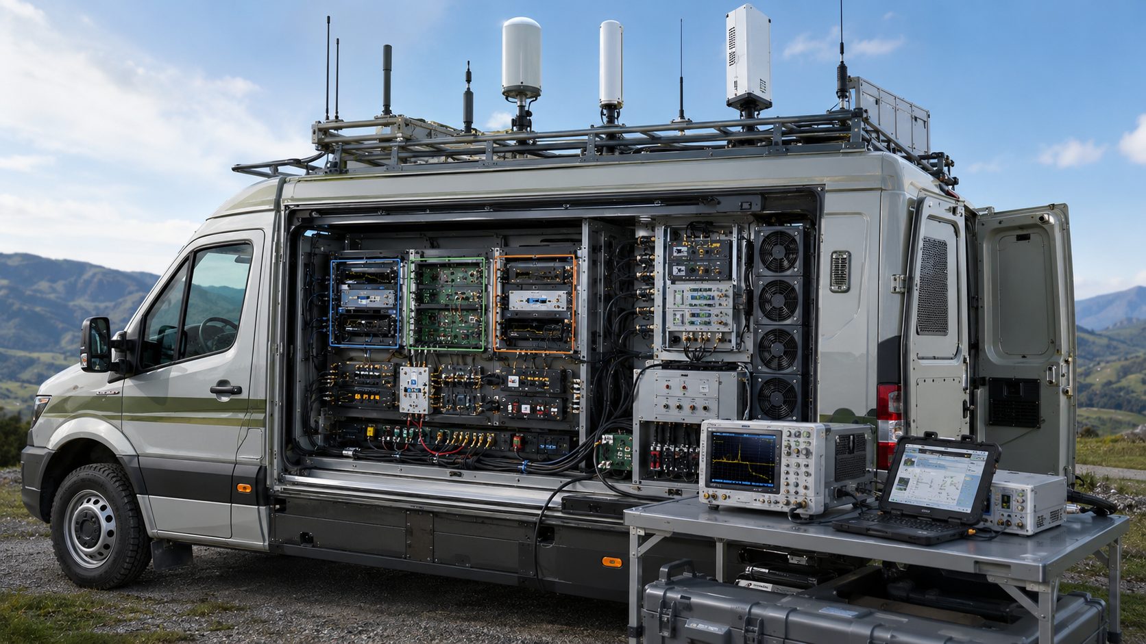
This article explains how engineers can plan RF PA Frequency Blocks in multi-band C-UAS cabinets, especially for vehicle-mounted systems where space, airflow, DC power, vibration, antenna placement, and maintenance access are limited.
1. What RF PA Frequency Blocks Mean in C-UAS Cabinets
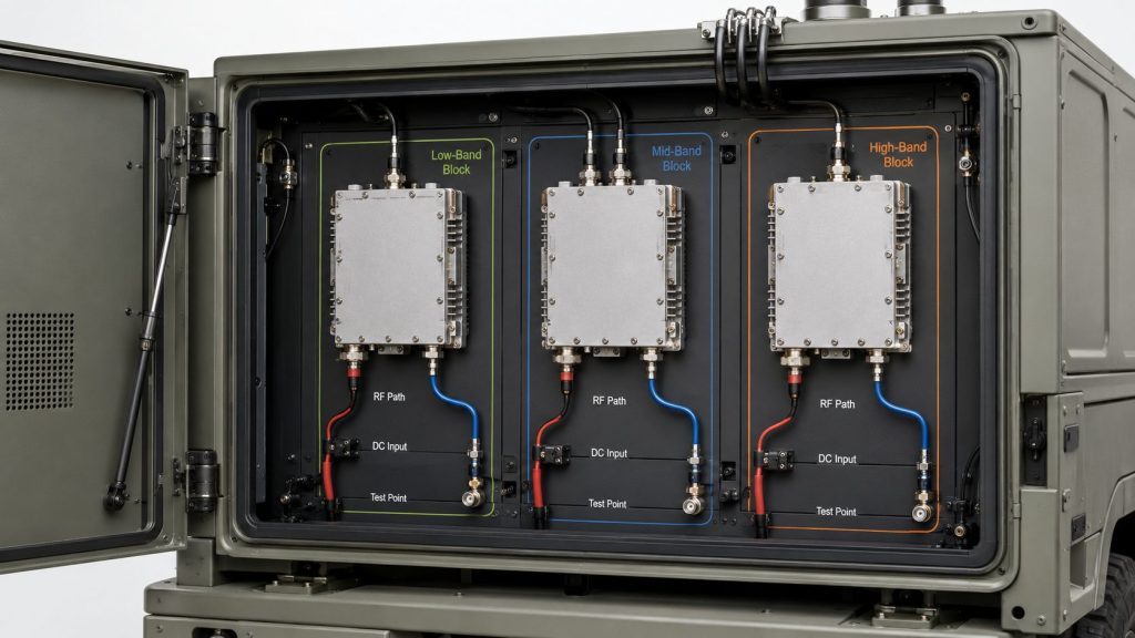
RF Power Amplifier Frequency Range becomes a useful cabinet design tool only when it is divided into RF PA frequency blocks that connect each band group to a module, antenna path, control rule, power load, thermal zone, and test reference. A frequency block is not just a label such as low band, mid band, or high band. It is a planned RF function inside the cabinet.
Here’s the engineering point: without frequency blocks, several good PA modules can still become one unclear RF cabinet. Engineers may know the rated band of each module, but not which block owns which target points, which antenna path carries the output, or which alarms belong to which RF path.
What should a frequency block define?
A useful block should answer more than “which MHz or GHz range does this cover?” It should define how that band group will be powered, cooled, routed, controlled, and tested.
A frequency block should normally define:
- Covered frequency group
- RF PA module or module family
- Output target
- Antenna path
- Filter or switching boundary
- Simultaneous operation condition
- DC current demand
- Thermal location
- Alarm feedback
- Test reference point
Key Takeaway: RF PA frequency blocks turn frequency range from a product parameter into a cabinet architecture that engineering, procurement, and acceptance teams can review.
| Wrong Assumption | Better Check |
|---|---|
| “Each PA module is one block automatically.” | Define the block by frequency role, path, power, and test boundary. |
| “A wide module removes block planning.” | Check which target points and antenna paths it actually serves. |
| “The cabinet is complete if the module bands cover the range.” | Confirm block ownership, control, cooling, and test evidence. |
| “Frequency blocks are only a drawing label.” | Treat them as RF, power, thermal, and control planning units. |
This table helps engineers avoid confusing product ranges with cabinet-level frequency architecture.
2. Why Is Block Planning Critical in Vehicle C-UAS Cabinets?
RF Power Amplifier Frequency Range needs stricter block planning in vehicle-mounted C-UAS cabinets because vehicle platforms limit space, DC power, cooling volume, antenna placement, vibration tolerance, and maintenance access. A fixed-site cabinet may allow more separation and airflow, but a vehicle cabinet forces every RF PA block to compete for space and resources.
The practical risk is clear: a module that looks easy to add on a bench may create real cabinet pressure once you include cables, airflow, power distribution, shock mounting, and antenna exits. Vehicle-mounted systems do not only need smaller hardware. They need a cleaner block architecture.
What makes vehicle cabinets harder?
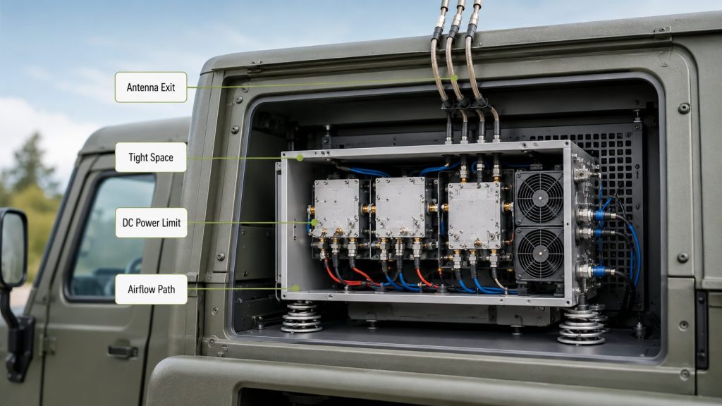
Vehicle cabinets usually operate inside a tighter physical and electrical boundary. Several RF PA blocks may need to fit near power supplies, fans, control boards, filters, cable exits, and service panels.
Vehicle-specific constraints include:
- Limited rack or enclosure space
- DC power constraints
- Concentrated heat
- Short but crowded RF paths
- Vibration and shock
- Restricted antenna locations
- Limited maintenance access
- Need for fast fault diagnosis
In broader Low-Altitude Security & C-UAS EW systems, these limits become more important when RF modules must work with antennas, control logic, and repeatable test evidence inside a complete platform.
Key Takeaway: Vehicle-mounted C-UAS cabinets need frequency-block planning because every block affects cabinet space, DC load, heat flow, antenna layout, and serviceability.
| Vehicle Condition | Selection Risk |
|---|---|
| Tight cabinet space | Modules fit, but cables and airflow may not. |
| Limited DC power | Multiple blocks may pull more current than expected. |
| Compact heat path | One hot block can heat nearby electronics. |
| Roof antenna limits | A block may lack a suitable antenna position. |
| Vibration and motion | Cable and connector stability become more important. |
This table shows why vehicle cabinet planning cannot be treated as a smaller version of fixed-site RF integration.
3. How to Group RF PA Frequency Blocks by Low, Mid, High Bands
RF Power Amplifier Frequency Range should be grouped into low, mid, and high RF PA blocks based on mission frequency needs, antenna paths, output targets, feeder loss, thermal load, and control logic. The grouping should not be based only on convenient product labels or a simple low-to-high frequency table.
This is where system integrators should pay attention: low, mid, and high bands create different cabinet pressures. A low-band block may need more antenna space. A mid-band block may carry several project-relevant frequencies. A high-band block may expose cable, connector, and antenna-path losses more clearly.
What should guide the grouping?
You can start with a low / mid / high structure, but you should refine it by engineering conditions. A clean block map should reflect both RF behavior and cabinet limits.
Use these questions before grouping:
- Which bands are actually required?
- Which bands may operate at the same time?
- Which antenna path serves each block?
- Which block has the highest duty cycle?
- Which block creates the most heat?
- Which block needs the shortest or cleanest RF path?
- Which block has the strictest test boundary?
A 2000–6000MHz RF Power Amplifier Module, for example, may be planned as a high-band block only after feeder loss, connector quality, antenna match, thermal load, and reflected-power status are included.
Key Takeaway: Low, mid, and high PA bands should be grouped by system behavior, not only by frequency labels.
| Band Group | Planning Question |
|---|---|
| Low-band block | Does the vehicle have enough antenna space and mounting margin? |
| Mid-band block | Can one block cover multiple project points without hidden weak zones? |
| High-band block | Are feeder loss, connector quality, and antenna match controlled? |
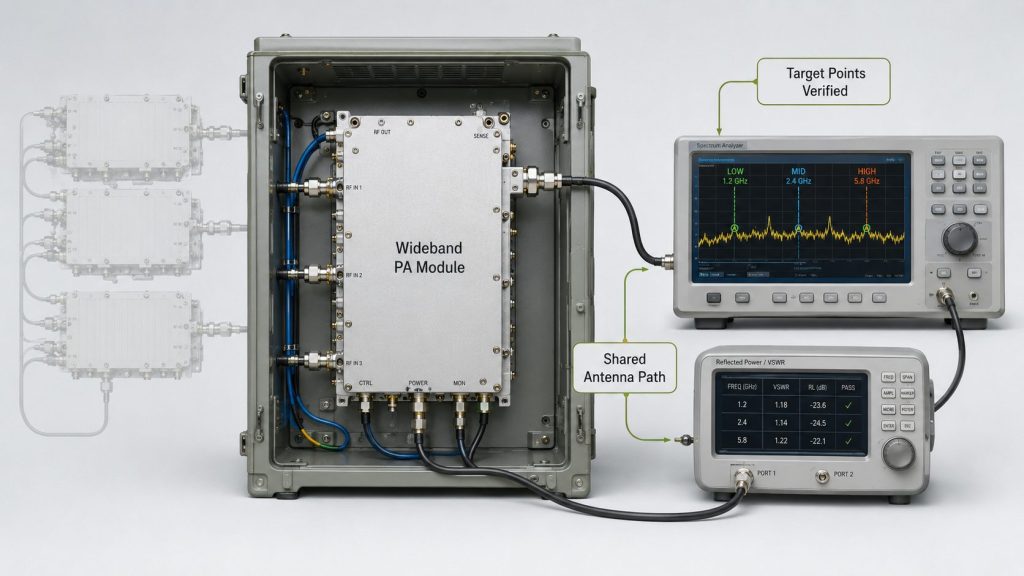
| Wideband block | Are low, center, high, and target points verified? |
| Narrower block | Does fixed-band efficiency justify extra paths and controls? |
This table helps engineers build block groups around real cabinet behavior instead of a simplified frequency chart.
4. When Should One Wideband Module Replace Multiple Blocks?
RF Power Amplifier Frequency Range from one wideband module should replace multiple narrower blocks only when target-frequency output, thermal behavior, VSWR margin, antenna path, control logic, and test evidence prove the simplified cabinet still works. A wider module can reduce hardware complexity, but it can also concentrate heat, current demand, and test responsibility.
Here’s the better check: do not ask whether the wideband module covers the band on paper. Ask whether it can support each required block condition inside the vehicle cabinet.
What makes wideband replacement useful or risky?
A wideband module can simplify the cabinet when it reduces module count, cable routing, control channels, and mechanical complexity. But if one module now carries several high-duty bands, the thermal and power budget may become harder, not easier.
A 300–2700MHz RF Power Amplifier Module can simplify some mid-band cabinet blocks, but target-frequency output, hot-state behavior, antenna path, and VSWR evidence must still be checked before it replaces several narrower paths.
Consider wideband replacement when:
- Target points are inside the tested band
- Output is proven at target points
- Thermal load is acceptable
- Antenna path supports the full block
- Control logic can separate operating states
- Full-band or key-point test data exists
Key Takeaway: A wideband module can reduce cabinet complexity only when it reduces risk at the system level, not just module count.
| Architecture Option | Trade-Off |
|---|---|
| One wideband block | Fewer modules, but higher full-band test responsibility. |
| Several narrower blocks | Better band focus, but more paths and controls. |
| Mixed architecture | Balanced flexibility, but needs clear block ownership. |
| Wider block with shared antenna | Simpler layout, but antenna match must be verified. |
| Separate block per antenna path | Cleaner RF behavior, but more cabinet complexity. |
This table helps engineers decide whether wideband consolidation improves the cabinet or only makes the block map look simpler.
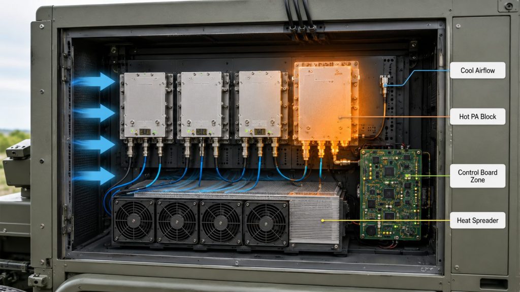
5. How to Use RF PA Frequency Blocks for Thermal Planning
RF Power Amplifier Frequency Range shapes thermal zones because each frequency block may create different heat, current draw, duty-cycle pressure, cable routing, and airflow requirements. In a vehicle-mounted cabinet, you cannot plan frequency blocks and thermal blocks separately.
Here’s the field reality: the hottest cabinet area is not always where you expect it from the frequency plan alone. A block with lower efficiency, higher duty cycle, tighter airflow, or heavy simultaneous operation can become the real thermal bottleneck.
What should thermal zoning include?
Thermal zoning should place high-heat RF PA blocks where heat can move out of the cabinet efficiently. It should also keep control boards, sensitive signal paths, and service access away from unnecessary heat exposure.
Review these items during layout:
- Highest-duty PA block
- High-current module position
- Air inlet and outlet path
- External heatsink contact area
- Cable routing near hot surfaces
- Control board separation
- Fan service access
- Temperature sensor location
- Alarm visibility per block
RF SKYPOWER supports wideband RF modules, CNC housings, copper heat spreading, protection feedback, and S/N-linked reports, helping integrators compare rated module data with real cabinet-level behavior.
Key Takeaway: Frequency blocks become thermal decisions once they enter a vehicle cabinet, so layout must protect airflow, heat transfer, and fault visibility.
| Thermal Condition | Cabinet Risk |
|---|---|
| High-heat blocks placed together | Local hot spots and early derating. |
| Cables block airflow | Hot-state output becomes unstable. |
| Wideband block carries several duties | Heat concentrates in one module path. |
| Control board near PA heat | Diagnostic and control reliability may suffer. |
| No block-level temperature record | Fault cause is harder to prove. |
This table helps engineers connect RF block grouping to thermal behavior before cabinet assembly begins.
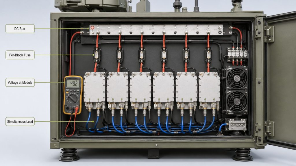
6. How Should Power Budget Be Planned for PA Blocks?
RF Power Amplifier Frequency Range should be tied to a block-level power budget because every PA block has a different current draw, duty condition, startup behavior, and simultaneous operation profile. Adding nominal current values from datasheets is not enough for a vehicle-mounted multi-band cabinet.
The selection risk appears here: one module may pass testing alone, but several blocks operating together may pull enough current to cause voltage drop, output reduction, controller alarms, or power-supply stress.
What should the power budget include?
A cabinet power budget should include more than RF PA current. Fans, SDR, switches, control electronics, monitoring devices, and any supporting loads must also be counted.
A stronger power review should include:
- Nominal and peak current per block
- Simultaneous operation scenarios
- Startup sequence
- Voltage drop at module terminals
- Cable gauge and DC distribution
- Fuse or breaker planning
- Cooling fan current
- Control system load
- Alarm behavior under voltage stress
- Test condition for full-load operation
Before planning a multi-band cabinet, engineers should review RF Power Amplifier Modules by frequency range, output level, duty cycle, cooling, protection feedback, and test data.
Key Takeaway: PA block planning must include current, voltage drop, startup, duty cycle, and simultaneous operation before the cabinet power architecture is approved.
| Power Condition | Better Starting Point |
|---|---|
| One PA block tested alone | Test expected simultaneous block combinations. |
| Nominal current only | Check peak and hot-state current. |
| Vehicle DC source assumed stable | Measure voltage at module terminals. |
| All blocks treated equal | Build a duty and priority profile. |
| Fan and control loads ignored | Include full cabinet electrical load. |
This table helps teams prevent a cabinet from passing single-module tests but failing under multi-block operating conditions.
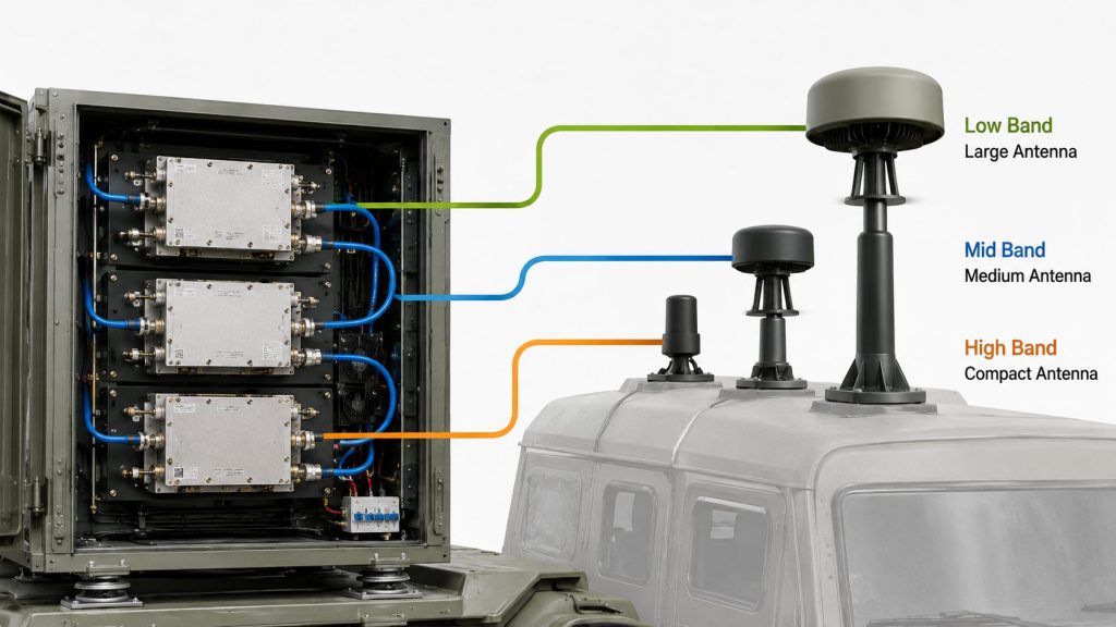
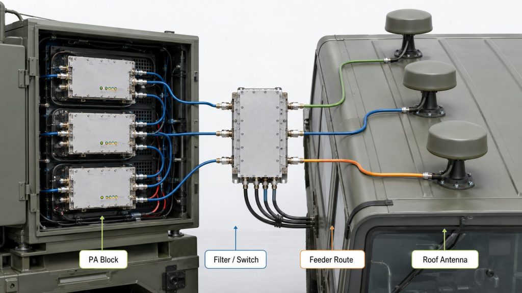
7. How to Match RF PA Frequency Blocks with Antenna Paths
RF Power Amplifier Frequency Range becomes useful only when each PA frequency block has a defined antenna path, feeder route, VSWR boundary, and vehicle mounting position. A PA block without a matching antenna path is not a usable cabinet block; it is only a rated module inside an enclosure.
The better check is simple: every frequency block should have an RF path drawing that shows how output leaves the PA module and reaches the intended antenna interface.
What should the antenna-path review include?
Antenna planning should be done at the block level. Wideband antennas can reduce antenna count, but they do not prove equal match or gain across every point. Narrower antennas may improve focus, but they increase roof layout pressure.
Check these items for each block:
- Antenna band
- Feeder length
- Connector type
- Adapter count
- Filter or switch path
- Antenna mounting position
- Isolation from other antennas
- VSWR or reflected-power evidence
- Antenna-port or system reference point
- Maintenance access
High power wideband antenna selection should follow the RF PA block plan because each frequency block needs a matching antenna path, feeder route, VSWR boundary, and vehicle mounting position.
Key Takeaway: Each PA block should be linked to a real antenna path, not just a module output connector.
| Antenna Path Item | Why It Matters |
|---|---|
| Antenna bandwidth | Confirms the block can radiate through a suitable load. |
| Feeder route | Affects loss, bend radius, and service access. |
| Connector quality | Changes VSWR and reflected-power behavior. |
| Mounting position | Affects vehicle integration and coverage direction. |
| Test reference point | Defines where output is judged. |
This table helps engineers verify that the PA block can reach the antenna under the same conditions used for acceptance.
8. How Should Control Logic Separate PA Blocks?
RF Power Amplifier Frequency Range needs block-level control logic because each PA path should be enabled, monitored, protected, diagnosed, and tested without turning the whole cabinet into one unclear RF channel. Multi-band cabinets require more than a single master on/off command.
This is where system integrators should pay attention: if all alarms collapse into one general fault, field diagnosis becomes slow. Operators need to know which block is active, which block is restricted, and which block generated the alarm.
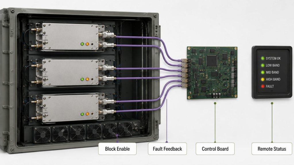
What should be visible per block?
Each frequency block should have enough control and feedback information to support integration, maintenance, and acceptance testing.
Block-level control should define:
- Enable / disable logic
- Operating status
- VSWR alarm
- Temperature alarm
- Voltage alarm
- Fault feedback
- Reset behavior
- Remote status option
- Startup sequence
- Simultaneous operation rules
- Lockout or protection behavior
SDR signal source and control logic should be aligned with RF PA blocks so each frequency path can be enabled, monitored, protected, and verified inside the cabinet.
Key Takeaway: Block-level control logic keeps a multi-band C-UAS cabinet diagnosable instead of making every RF path depend on one unclear status signal.
| Control Problem | System Impact |
|---|---|
| One alarm for all blocks | Fault location becomes unclear. |
| No block enable status | Operators cannot confirm which path is active. |
| No startup priority | Power peaks may become unpredictable. |
| No thermal lockout logic | Hot blocks may be restarted too quickly. |
| No VSWR category | Antenna-path faults may look like PA faults. |
This table helps engineers decide what feedback must be visible before a multi-band cabinet is approved.
9. What Test Evidence Proves RF PA Frequency Blocks Work
RF Power Amplifier Frequency Range is proven at cabinet level only when module-level, block-level, antenna-path, thermal, power, alarm, and control evidence all support the same frequency-block plan. Individual PA test reports are important, but they do not prove the whole vehicle cabinet is ready.
Here’s the practical risk: a cabinet can pass module-by-module output checks and still fail when several blocks operate together. The acceptance plan must test the architecture, not only the components.
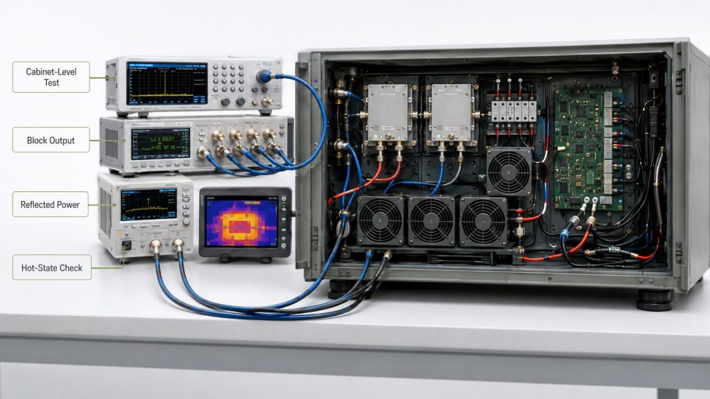
What evidence should be included?
A useful test package should show whether each frequency block works under the conditions expected in the vehicle. It should also show what happens when multiple blocks are active.
Cabinet readiness evidence should include:
- Module output data
- Block-level frequency test
- Target-point output
- Current and voltage per block
- Thermal behavior per block
- Antenna-path VSWR or reflected power
- Simultaneous block operation
- Alarm and protection status
- Control feedback record
- S/N-linked reports
- Cabinet-level test boundary
After RF PA frequency blocks are planned, multi-band C-UAS systems should verify RF power consistency across channels, antenna paths, thermal states, and cabinet positions.
Key Takeaway: Cabinet readiness is proven by block-level and cabinet-level evidence, not by isolated module datasheets alone.
| Weak Evidence | Better Evidence |
|---|---|
| One module output screenshot | Block-level target-frequency data. |
| Dummy load only | Antenna-path or system reference data. |
| Cold-state power reading | Hot-state and duty-cycle behavior. |
| Total cabinet alarm only | Block-level fault category. |
| Single-module test | Simultaneous block operation test. |
This table helps acceptance teams separate component validation from cabinet validation.
10. What RF PA Frequency Blocks Require Before Cabinet RFQore Cabinet Design?
RF Power Amplifier Frequency Range should be written into the RFQ as frequency blocks, output targets, antenna paths, power budget, cooling conditions, control feedback, protection requirements, and test-report expectations before vehicle cabinet design begins. A vague request for a “multi-band C-UAS PA cabinet” leaves too many decisions undefined.
The better check is simple: send the supplier a block plan, not just a product wish list. Even an early draft block plan helps the factory review module grouping, layout pressure, and test feasibility.

What information should the RFQ include?
A cabinet RFQ should describe how the blocks are expected to work inside the vehicle platform. If some information is unknown, label it as open rather than letting the supplier guess.
Useful RFQ fields include:
- Vehicle platform type
- Cabinet size limit
- Target frequency blocks
- Target frequency points
- Required output per block
- Simultaneous operation condition
- Duty cycle
- Supply voltage
- DC power limit
- Cooling method
- Antenna path per block
- Feeder length
- VSWR or reflected-power requirement
- Control interface
- Alarm feedback
- Test report format
- S/N-linked report requirement
- Maintenance access needs
As a source factory for RF Power Amplifier Modules and C-UAS core components, RF SKYPOWER can help integrators review frequency blocks, PA module grouping, antenna paths, power budget, thermal zones, protection feedback, and repeatable test evidence before multi-band cabinet approval.
Key Takeaway: A strong RFQ turns frequency range into a cabinet-level engineering plan that suppliers can review, price, and validate more accurately.
| RFQ Item | Why It Matters |
|---|---|
| Frequency blocks | Defines module grouping and ownership. |
| Simultaneous operation | Defines power and heat stress. |
| Antenna path | Defines real RF load condition. |
| Cooling method | Defines hot-state output risk. |
| Control feedback | Defines diagnostic visibility. |
| Test report format | Defines acceptance evidence. |
This table helps procurement teams turn a broad cabinet request into a reviewable engineering package.
FAQ
Can one wideband PA module replace several cabinet blocks?
Yes, if the target-frequency output, hot-state behavior, antenna path, VSWR margin, control logic, and test evidence support the combined block. A wideband label alone does not prove that it can replace several narrower blocks inside a vehicle cabinet.
What should I check before grouping PA modules?
Start with target frequency points, simultaneous operation, output per block, antenna path, DC current, cooling, control feedback, and test reference point. These items decide whether the grouping works beyond the frequency table.
How do I know if a cabinet has too many RF PA blocks?
A cabinet may have too many blocks if cable routing, power distribution, airflow, control wiring, and maintenance access become unclear. The issue is not only module count; it is whether every block can be powered, cooled, controlled, and tested.
What’s the best test for a multi-band C-UAS cabinet?
The best test combines module-level data, block-level target-frequency checks, antenna-path VSWR or reflected power, hot-state operation, simultaneous block testing, and alarm feedback verification. A single PA-port output reading is not enough.
When should I define antenna paths?
Define antenna paths before final PA module selection. Each RF PA block should be linked to an antenna band, feeder route, connector plan, VSWR boundary, and vehicle mounting position.
Conclusion
A multi-band vehicle-mounted C-UAS cabinet should not be designed by stacking RF PA modules according to rated frequency range alone. This article showed how engineers can turn RF Power Amplifier Frequency Range into a cabinet-level frequency-block plan that connects each PA block with output targets, antenna paths, feeder routes, DC power, thermal zones, control feedback, protection behavior, and repeatable test evidence.
RF SKYPOWER can support vehicle-mounted C-UAS integrators by reviewing RF PA module grouping, wideband and high-band module options, antenna-path assumptions, power and thermal limits, protection feedback, and block-level test expectations. If your team is preparing a multi-band cabinet RFQ, contact us today to review your frequency block plan before final module selection.
Field-ready C-UAS cabinets are built from verified RF blocks, not from catalog frequency ranges alone.