











RF PA expansion can appear fully supported in an airport C-UAS proposal—and still have no usable upgrade path.
A quotation may mention a wide frequency range, an empty cabinet position, or a future module option. None of these proves that a later frequency group will have an approved PA branch, sufficient 28 V DC capacity, a suitable cooling interface, an antenna route, a control state, or a defined acceptance method.
The first project phase does not need to purchase every possible future module. It does need to separate current requirements from future possibilities before the cabinet and RF architecture are frozen.
RF Power Amplifier Modules should therefore be reviewed against a phase-based expansion boundary—not only the widest catalog frequency label.
Before approving the RFQ, the project must answer one question:
What is installed now, what is only reserved for later, and what must be requalified before a future frequency group becomes operational?
All deployment, frequency, and operating requirements must follow the customer’s lawful authority and approved spectrum plan.
1. Why “Future Expansion Supported” Is Not an Approval Boundary
The phrase “future expansion supported” can describe several different supplier scopes.
It may mean:
- the current PA has a wider catalog frequency label;
- the cabinet contains an empty mounting position;
- an unused DC connector is available;
- a future RF connector has been considered;
- or the supplier expects to redesign the system later.
These are not equivalent upgrade paths.
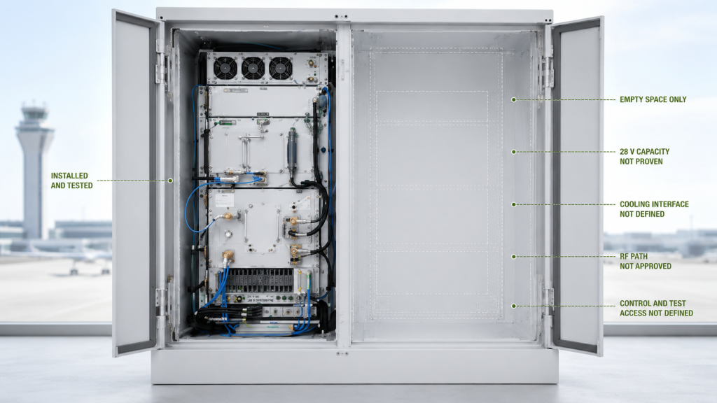
A wider PA label does not prove output at future priority frequencies. An empty cabinet position does not prove that the future module will fit. A spare connector does not prove that the 28 V distribution can support the additional loaded current.
Airport C-UAS projects may also have project-specific protected bands. These boundaries can affect filtering, switching, control permissions, antenna assignment, and the later acceptance plan.
A comparable RFQ must therefore replace broad roadmap language with a controlled band-status map.
Phase-one acceptance applies only to the installed and tested configuration. It should not be treated as approval for RF hardware, paths, or operating states that do not yet exist.
Projects still deciding whether expansion readiness is necessary should first review RF PA expansion beyond common drone bands before defining the supplier scope.
2. How to Separate Current, Future, Protected, and Unconfirmed Bands
A future-ready RFQ should not place every frequency range in one undifferentiated list.
Each range needs a status that states what is approved now, what may be defined or reserved, and what cannot yet be claimed.
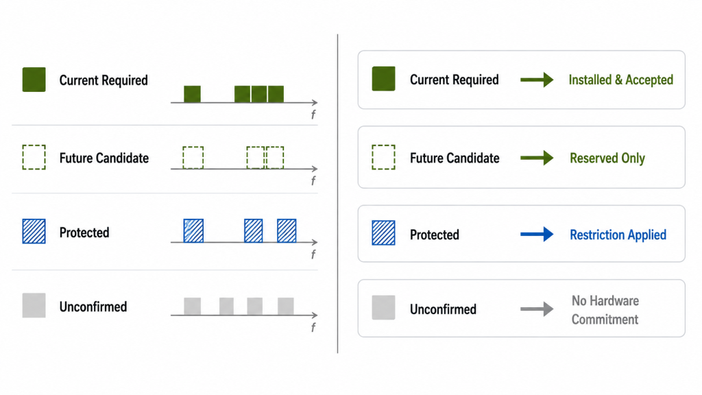
Current Required Bands
Current required bands belong to the approved phase-one operating scope.
The RFQ needs to define:
- priority frequency points;
- output targets and reference points;
- operating duty;
- antenna and feeder paths;
- control and protection requirements;
- and acceptance limits.
The installed PA path should be tested against these conditions before shipment or system release.
Future Candidate Bands
A future candidate may become part of a later project phase, but it is not yet an active requirement.
It may justify reserving:
- cabinet space;
- 28 V DC capacity;
- cooling access;
- RF connector positions;
- antenna routing;
- control capacity;
- or future test access.
It does not justify claiming future RF output, current, temperature, VSWR, or system compatibility before the future hardware and RF path are defined.
Protected Bands
Protected bands define project-specific operating and RF-path restrictions.
Depending on the approved architecture, they may affect:
- filtering;
- switching;
- control permissions;
- antenna assignment;
- and the later acceptance plan.
A generic PA frequency specification does not prove compliance with a protected boundary. The requirement must be connected to the complete project configuration.
Unconfirmed Bands
An unconfirmed range has not reached the point where a hardware commitment is justified.
The project may still be reviewing:
- lawful authorization;
- exact frequency points;
- output requirements;
- antenna architecture;
- deployment phase;
- or whether the range is needed.
Only justified interface flexibility should be preserved at this stage. Purchasing wider or higher-power hardware too early may increase cost, current, heat, cabinet size, and test scope without creating a qualified expansion path.
Airport C-UAS Band-Status Matrix
| Band Status | What It Means Now | What Must Be Defined or Reserved Now | What Cannot Yet Be Claimed |
|---|---|---|---|
| Current required | Installed and accepted in phase one | Interfaces and operating conditions for approved hardware | Performance outside the tested configuration |
| Future candidate | Possible later requirement | Space, DC, cooling, RF, control, and test access where justified | Future RF output or system compatibility |
| Protected | Project-defined operating or RF-path restriction | Filtering, switching, control, antenna, and test boundaries | Compliance without complete-path evidence |
| Unconfirmed | Requirement not yet approved | Limited interface flexibility | Hardware suitability or future qualification |
The matrix prevents roadmap language from being mistaken for approved hardware scope.
3. When to Use Wider PA Hardware or Reserve a Future Branch
Future expansion does not always require a separate module.
The project normally has three architecture choices:
- install wider PA hardware during phase one;
- reserve an independent future RF branch;
- add a separate expansion enclosure later.
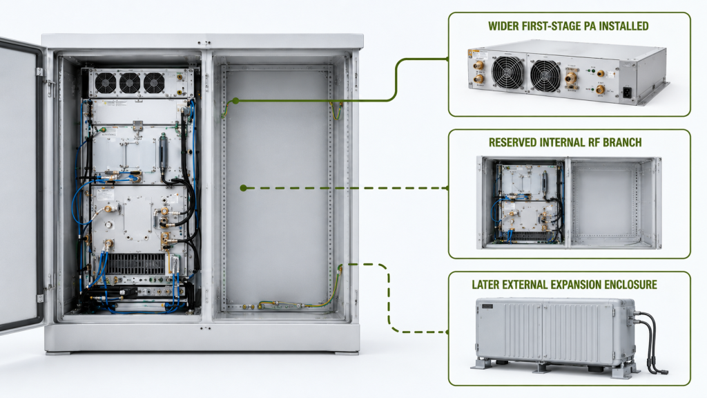
Wider First-Stage PA Hardware
A wider first-stage PA path may be practical when:
- future priority points are already known;
- the required output can be verified;
- the existing antenna and RF path can support them;
- the operating modes do not require conflicting filtering or switching;
- and the hardware remains within the phase-one cabinet limits.
The benefit is not the wider label itself. The benefit is the possibility of qualifying one controlled RF path before the first cabinet is released.
A future frequency point is not qualified merely because it falls inside the published PA range.
Detailed wideband, narrowband, and mixed-path selection should continue with the C-UAS RF PA selection workflow.
Reserved Independent RF Branch
A reserved branch is more suitable when the future range or operating architecture remains uncertain, but the phase-one cabinet can preserve a controlled:
- mechanical boundary;
- 28 V interface;
- cooling interface;
- RF route;
- control channel;
- and test reference.
The reserve must be revision-linked and reviewable. An empty position without defined interfaces is not an engineering-ready expansion path.
Later External Expansion
A later enclosure or external RF assembly may be more realistic when the first cabinet cannot support the future branch without major changes.
This route creates a separate integration and acceptance scope, but it avoids forcing uncertain future requirements into the phase-one cabinet.
RF SKYPOWER can review whether the project needs wider first-stage PA hardware, a reserved independent branch, or a later expansion enclosure before the phase-one cabinet is released.
4. What Evidence Proves That Expansion Capacity Was Reserved
A supplier does not need to prove the RF performance of hardware that has not been installed.
The supplier does need to prove that each claimed reserve has a defined and approved boundary.
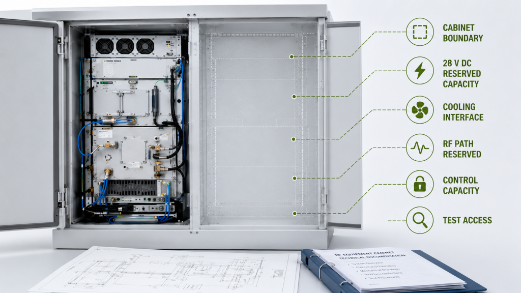
Expansion Reserve Boundary
| Reserve Area | Evidence Required Now | What Remains Unproven |
|---|---|---|
| Cabinet | Approved space, access, mounting boundary, and revision | Final fit of an unselected future module |
| 28 V DC | Branch, cable, connector, protection, and load assumption | Loaded Vdc and Idc with future hardware |
| Cooling | Airflow or cold-plate interface and available boundary | Future hot-state output and temperature |
| RF path | Connector, switch or filter route, feeder provision, and reference point | Final path loss, corrected output, and VSWR |
| Control | Address, enable, alarm, protection, and recovery capacity | Future protocol and fault behavior |
| Test access | RF, DC, thermal, and logging access | Future acceptance result |
A claimed cabinet reserve should identify usable dimensions, mounting responsibility, service access, and the controlling layout revision.
A claimed 28 V reserve should identify the branch, cable and connector ratings, protection boundary, and assumed simultaneous load. A spare fuse position alone does not prove adequate future capacity.
The project’s remaining capacity should be reviewed through the RF PA upgrade margin rather than inferred from nominal power-supply or cabinet ratings.
Cooling, RF-path, and control records can prove that defined interfaces remain available. They cannot prove the future module’s hot-state performance, final path loss, antenna match, protocol compatibility, or fault behavior.
Reserve evidence proves that an interface exists. It does not prove the performance of hardware that has not yet been installed.
5. What Must Be Proven Now—and Requalified Later
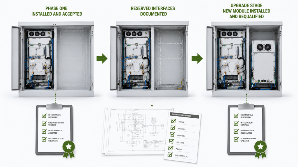
Future expansion evidence should be divided into three levels:
- phase-one performance evidence;
- reserve-boundary evidence;
- upgrade-stage evidence.
Phase-One Performance Evidence
Phase-one evidence applies only to the installed and released configuration.
It should connect:
- module model and S/N;
- controlled configuration revision;
- required frequency points;
- corrected RF output and reference point;
- loaded Vdc and Idc;
- load and thermal condition;
- and the applicable acceptance conclusion.
Shipment and release decisions should rely on S/N-linked RF PA acceptance evidence rather than representative data that cannot be connected to the delivered modules.
Reserve-Boundary Evidence
Reserve evidence documents the interfaces and capacity preserved for later use.
It may include:
- cabinet dimensions;
- the approved 28 V branch;
- the cooling interface;
- an RF connector or switch position;
- antenna-route provision;
- control capacity;
- test access;
- and the controlling reserve revision.
This evidence supports a future upgrade review. It does not qualify the future PA or installed RF path.
Upgrade-Stage Evidence
Once the future branch is installed, the project needs a new acceptance scope.
The updated evidence should connect:
- the new hardware identity and S/N;
- the revised cabinet and RF-path configuration;
- updated RF, power, thermal, antenna, control, and protection results;
- any permitted simultaneous-operation condition;
- and a new release conclusion.
A phase-one report remains evidence for the phase-one configuration. It does not automatically approve a later hardware, RF-path, antenna, or control change.
6. What to Put in the Airport C-UAS Expansion RFQ
The RFQ should separate:
- installed hardware;
- reserved interfaces;
- deferred requirements;
- future qualification responsibilities;
- and the event that starts the upgrade review.
Without these distinctions, two suppliers may both state “future expansion supported” while offering completely different engineering scopes.
Future Expansion RFQ and Evidence Matrix
| RFQ Area | Defined or Included in Phase One | Reserved or Deferred | Requalification Requirement |
|---|---|---|---|
| Frequency scope | Current required points | Future candidate ranges | Final future frequencies and limits |
| PA hardware | Installed phase-one modules | Module position or interface where defined | Future module performance and protection |
| Cabinet | Approved current layout | Mounting and service boundary | Final module fit and installation |
| 28 V DC | Current loaded Vdc and Idc | Branch, cable, connector, and capacity boundary | Loaded result with future hardware |
| Cooling | Current cooling configuration | Future thermal interface | Future hot-state output and temperature |
| RF path | Current filters, switches, cables, and connectors | Future route or connector position | Final path loss and corrected output |
| Antenna path | Current feeder and antenna assignment | Future port or route | Match, VSWR, and antenna-end result |
| Control | Current enable, status, alarm, and recovery logic | Address or interface capacity | Future command and fault behavior |
| Protected boundary | Current approved restriction | Future boundary where defined | Complete-path evidence after installation |
| Upgrade trigger | Approved event, decision owner, and controlling revision | Review workflow | New quotation, test plan, and release status |
| Acceptance | Current S/N-linked evidence | Reserve configuration record | Updated S/N-linked system release |
Define the Upgrade Trigger
A future candidate should not become an active requirement through an informal email or an uncontrolled drawing change.
The RFQ needs to state:
- what event starts the phase-two review;
- who approves the new band status;
- which document revision becomes controlling;
- whether a new quotation is required;
- and when the updated test plan must be approved.
Possible triggers may include:
- formal confirmation of lawful operating authority;
- approval of exact frequency and output requirements;
- release of a customer change order;
- approval of the future antenna architecture;
- or authorization of a new cabinet configuration.
The trigger closes the gap between a future possibility and an executable engineering change.
Information the Customer Should Provide
A comparable airport C-UAS expansion RFQ should include:
- current required bands;
- future candidate bands;
- protected bands;
- unconfirmed ranges;
- phase-one output targets and reference points;
- installed hardware scope;
- reserved cabinet and 28 V boundaries;
- cooling reserve;
- antenna and feeder provisions;
- control and alarm capacity;
- simultaneous-operation assumptions;
- current acceptance scope;
- upgrade trigger and approval owner;
- future requalification scope;
- quantity;
- and configuration-document ownership.
A supplier response should clearly distinguish what is installed, what is reserved, what is deferred or undefined, and what must be retested after expansion.
Conclusion
Future RF PA frequency expansion is not proven by a wideband label, an empty cabinet position, or a roadmap statement. A usable expansion plan separates current requirements, future candidates, protected boundaries, and unconfirmed ranges while distinguishing installed hardware from reserved interfaces and phase-one acceptance from future requalification.
RF SKYPOWER can support an early review of your airport C-UAS expansion RFQ. Send the current and future band status, protected boundaries, output reference, phase-one hardware scope, reserved cabinet and 28 V capacity, cooling and antenna provisions, control reserve, upgrade trigger, quantity, and required upgrade-stage evidence.
Submit your expansion RFQ before the first cabinet is frozen so installed hardware, reserved interfaces, approval ownership, and future requalification responsibilities can be reviewed separately.