


RF Power Amplifier Frequency Range should not be planned as separate module bands with no transition review, especially in border and coastal C-UAS systems. When two RF PA modules meet near a frequency boundary, frequency overlap can provide useful transition margin, but only if the overlap zone remains usable after output power, feeder loss, antenna match, thermal behavior, VSWR, control logic, and test evidence are included.
The central conflict is simple: paper overlap can make a module table look safer, but usable overlap must prove that the installed system still has output, antenna-path margin, stable protection behavior, and clear control logic in the transition zone. If overlap is not tested, it may hide the same weak boundary that it was supposed to solve.
This article explains when frequency overlap is useful in multi-module RF PA systems, when it creates unnecessary complexity, and what engineers should write into the RFQ before approving RF Power Amplifier Modules for border or coastal C-UAS deployment.
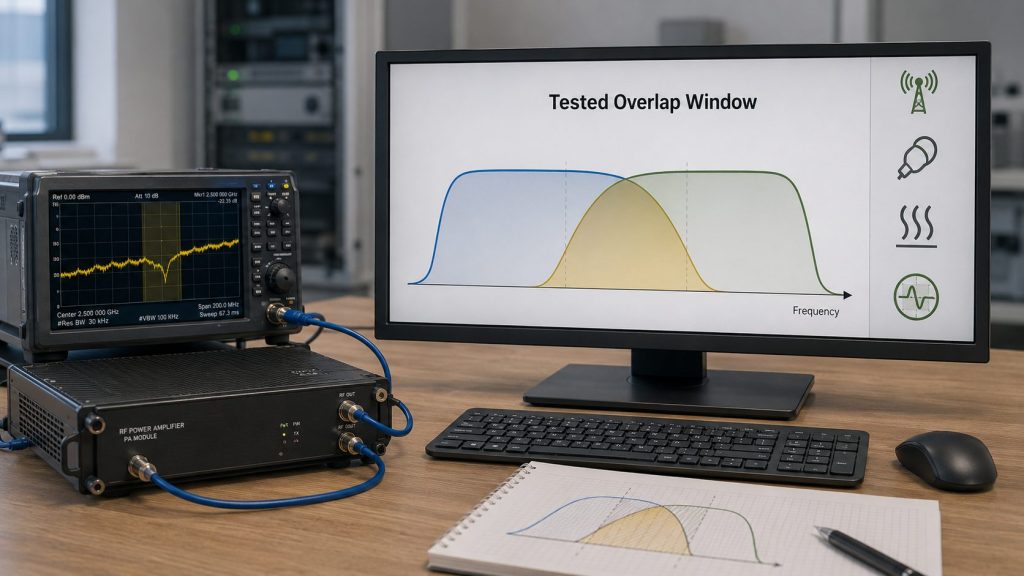
1. What Frequency Overlap Means Between RF PA Modules
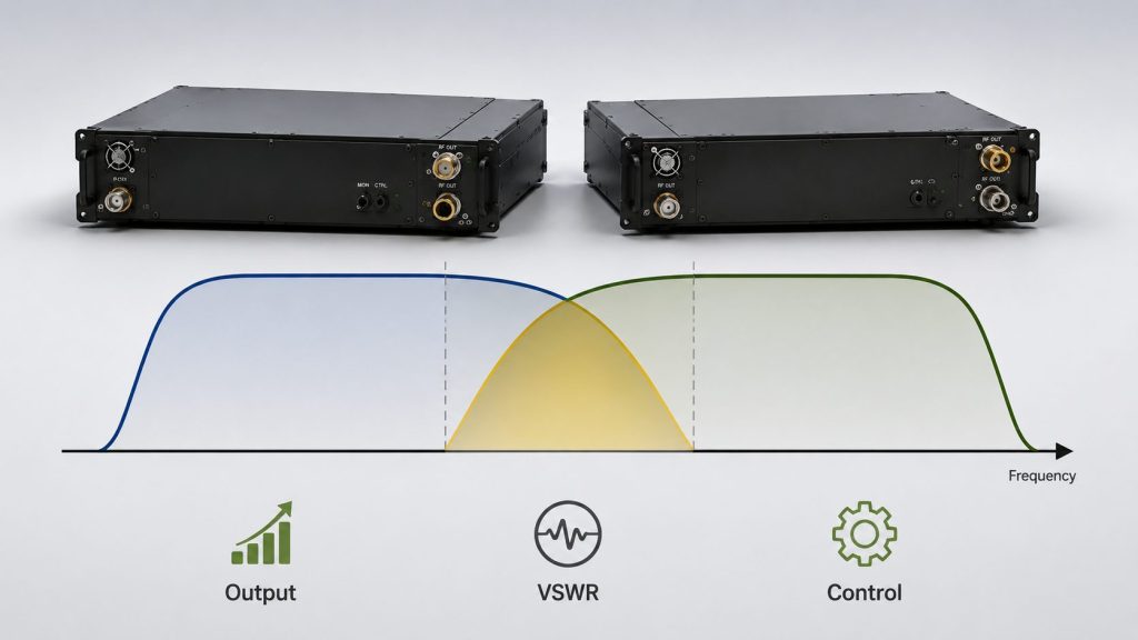
RF Power Amplifier Frequency Range overlap means two RF PA modules nominally support part of the same frequency range, giving engineers a shared transition zone between adjacent modules. That shared range can be useful, but it is not automatically usable. A true overlap zone must still deliver output, thermal stability, VSWR margin, antenna-path performance, control clarity, and test evidence.
Here’s the engineering point: overlap is not just two numbers crossing on a datasheet. It should be treated as a system-level transition area where two module paths, antenna routes, and protection states may need comparison.
What separates paper overlap from usable overlap?
Paper overlap exists when two rated module bands share a frequency range. Usable overlap exists when that shared range works under the same conditions expected in the deployed system.
Useful overlap should confirm:
- Output power at overlap points
- Gain behavior near module edges
- Hot-state stability
- Antenna-path compatibility
- VSWR or reflected-power status
- Clear module responsibility
- Control and alarm feedback
- Repeatable test report evidence
Key Takeaway: Frequency overlap becomes valuable only when the shared band is proven as a usable RF transition zone, not just a datasheet intersection.
| Wrong Assumption | Better Check |
|---|---|
| “The module bands overlap, so the system is safe.” | Verify output, antenna path, VSWR, heat, and control behavior. |
| “Overlap removes all boundary risk.” | Test the transition zone under real system conditions. |
| “Overlap only means extra bandwidth.” | Treat overlap as a system margin that must be proven. |
| “One module report is enough.” | Compare both module paths or define a tested primary path. |
This table helps engineers separate rated module overlap from real transition margin.
2. Why Is Overlap Valuable in Border and Coastal C-UAS Sites?
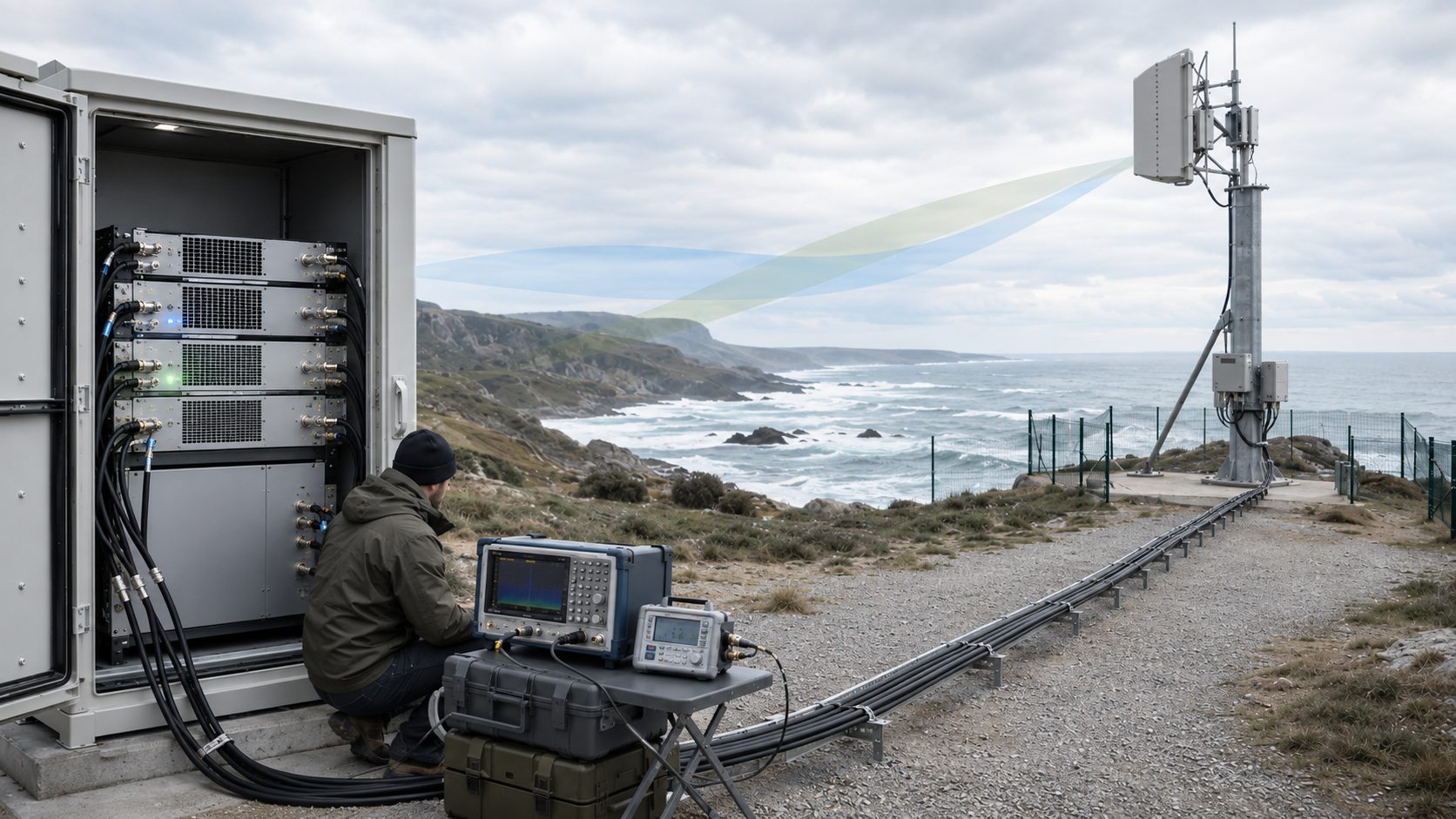
RF Power Amplifier Frequency Range overlap is valuable in border and coastal C-UAS sites because long feeder paths, outdoor RF transitions, maintenance difficulty, and environmental stress can turn a small module-boundary weakness into a field coverage risk. In these sites, a weak transition frequency may be harder to diagnose and more expensive to correct after deployment.
The practical risk is clear: a module boundary that looks acceptable at the PA port may become weaker after cables, connectors, lightning protection, waterproof joints, directional antennas, and outdoor aging are included. This is why overlap must be evaluated at the installed RF path, not only at the cabinet output.
What makes these sites more sensitive?
Border and coastal deployments often have distributed sites, long operating periods, harsh weather, and fewer maintenance windows. A small transition weakness can create repeated service work if it appears after installation.
Overlap becomes more valuable when the system includes:
- Long feeder routes
- Outdoor cabinets
- Tower or mast antennas
- Lightning protection devices
- Multiple connector transitions
- Salt, humidity, wind, or rain exposure
- Long-duty operating profiles
- Remote maintenance conditions
In Low-Altitude Security & C-UAS EW systems, RF Power Amplifier Frequency Range should be reviewed together with overlap zones, antenna paths, feeder loss, control logic, and test evidence.
Key Takeaway: In border and coastal sites, overlap is useful when it reduces transition risk that would otherwise be amplified by outdoor RF paths and limited maintenance access.
| Field Condition | Selection Risk |
|---|---|
| Long feeder path | PA-port overlap may shrink at the antenna end. |
| Outdoor connectors | Local mismatch may affect transition frequencies. |
| Remote site access | A weak boundary becomes harder to fix later. |
| Long-duty operation | Hot-state overlap may differ from cold-state data. |
| Harsh environment | Cable and connector changes can expose weak margins. |
This table helps teams decide when overlap is worth verifying beyond the datasheet.
3. How Frequency Overlap Prevents RF PA Module Gaps
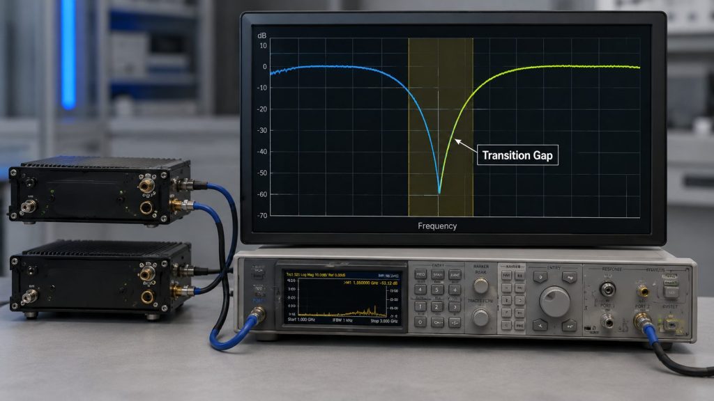
RF Power Amplifier Frequency Range overlap prevents frequency gaps only when the transition zone is tested as usable coverage. If two rated frequency ranges merely touch or overlap on paper, but output drops, VSWR rises, antenna match weakens, or hot-state performance falls at the boundary, the system may still have a hidden gap.
This is where system integrators should pay attention: the most dangerous gap is not always the obvious empty space between two module ranges. It may be a hidden gap inside a transition zone that was never tested at the actual target points.
What is the difference between obvious and hidden gaps?
An obvious gap appears when one module ends before the next module begins. A hidden gap appears when the datasheet looks continuous, but the installed system cannot support the transition frequency with enough usable margin.
Overlap helps prevent gaps when engineers verify:
- Module A edge output
- Module B overlap output
- Filter transition behavior
- Antenna bandwidth
- Feeder and connector loss
- VSWR or reflected power
- Hot-state output
- Control responsibility in the overlap zone
Frequency gaps between RF PA modules should be reviewed before engineers decide whether overlap is needed at the transition zone.
Key Takeaway: Overlap prevents gaps only when it creates tested transition coverage, not when it merely fills a table between two frequency ranges.
| Gap Type | Better Starting Point |
|---|---|
| Mathematical gap | Add or adjust overlap at the module range level. |
| Hidden edge weakness | Test output and gain near both module edges. |
| Antenna-path gap | Verify overlap at feeder end or antenna port. |
| Hot-state gap | Repeat overlap tests after thermal load builds. |
| Control gap | Define which module owns the transition point. |
This table helps engineers identify whether overlap is solving a real RF gap or only improving the drawing.
4. How Frequency Overlap Improves Band-Edge Margin
RF Power Amplifier Frequency Range overlap can improve band-edge output margin by giving engineers a tested alternative module path when one amplifier’s edge frequency has less gain, efficiency, thermal margin, or antenna-path stability. It is not a guarantee of higher output, but it can provide a better choice near weak edges.
Here’s the better check: do not force a target point onto the weakest edge of one module if the adjacent module can support the same point more cleanly inside the overlap zone. The value of overlap is the ability to choose the stronger verified path.
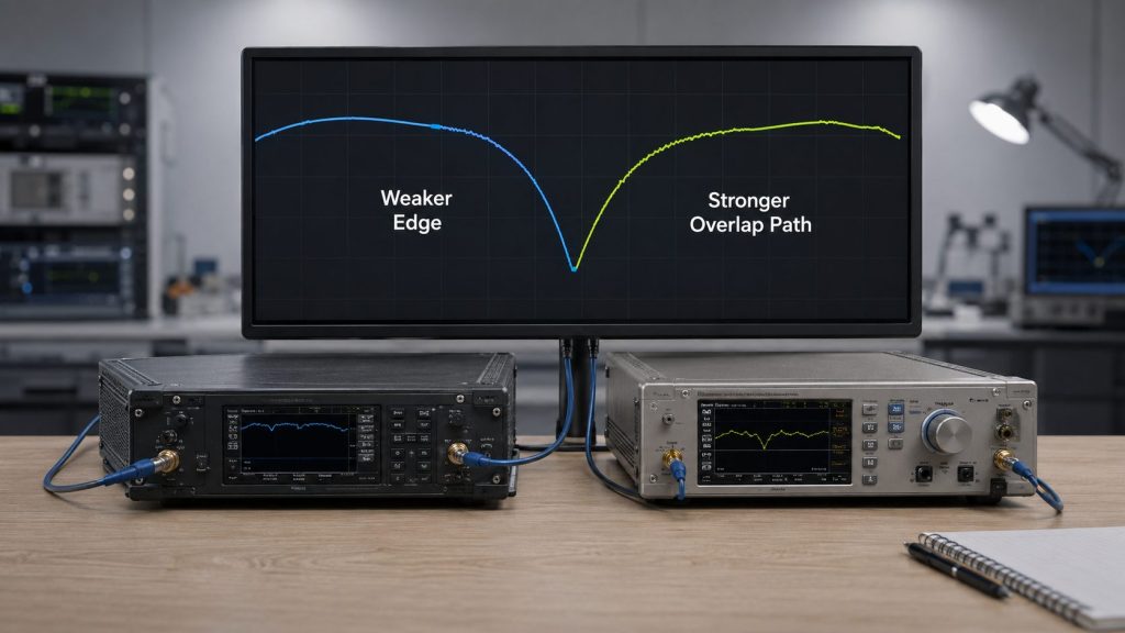
What should be compared at the band edge?
PA modules often behave differently near their lower or upper edges. Output, gain flatness, current draw, heat, and reflected-power behavior may change compared with the center of the band.
Compare these items in the overlap zone:
- Module A output at edge
- Module B output at same point
- Gain flatness
- Current draw
- Temperature rise
- VSWR or reflected power
- Antenna-path output
- Duty-cycle behavior
- Alarm feedback
A 300–2700MHz RF Power Amplifier Module can reduce some mid-band transition risks, but overlap value still depends on target-frequency output, thermal behavior, antenna path, and VSWR evidence.
Key Takeaway: Overlap improves band-edge margin only when the alternative module path is stronger under the same RF, thermal, and antenna-path conditions.
| Band-Edge Condition | Overlap Value |
|---|---|
| Edge output drops | Adjacent module may carry the target point better. |
| Gain becomes uneven | Overlap provides a comparison zone. |
| Heat rises near edge | Another module may offer better thermal margin. |
| VSWR becomes sensitive | Antenna-path testing decides usefulness. |
| Target point sits near boundary | Overlap reduces dependence on one weak edge. |
This table helps engineers use overlap as a tested margin, not as a blind band-extension claim.
5. How Much Frequency Overlap Is Enough?
RF Power Amplifier Frequency Range overlap is enough when it covers transition uncertainty after module edge behavior, filter roll-off, antenna bandwidth, feeder loss, VSWR, heat, duty cycle, and acceptance evidence are included. There is no universal overlap number that fits every low-band, mid-band, high-band, wideband, or narrowband system.
The practical risk is clear: asking for a fixed overlap width without knowing the target points and RF path may create either too little margin or unnecessary hardware complexity. The correct overlap size comes from the transition risk, not from a convenient MHz value.
What should define the overlap width?
A useful overlap zone should be wide enough to cover real uncertainty, but not so wide that it adds cost, heat, control complexity, and testing burden without value.
Define overlap by reviewing:
- Target frequency locations
- Module edge output behavior
- Gain flatness
- Filter transition width
- Antenna bandwidth
- Feeder loss
- VSWR stability
- Hot-state output
- Duty cycle
- Protected bands
- Future expansion needs
- Test report coverage
Key Takeaway: Enough overlap is the smallest tested transition margin that keeps target points away from weak module, antenna, and thermal boundaries.
| Selection Condition | Recommended Path |
|---|---|
| Target point near module edge | Use enough overlap to test another module path. |
| Filter transition is wide | Increase overlap review around the roll-off area. |
| Antenna match is narrow | Do not count overlap outside usable antenna range. |
| High feeder loss exists | Verify overlap at antenna-side reference points. |
| Protected bands are nearby | Avoid excessive overlap that complicates control. |
This table helps engineers define overlap by usable margin rather than by a generic number.
6. When Can Frequency Overlap Create New Problems?
RF Power Amplifier Frequency Range overlap can create new problems when it adds cost, heat, power demand, switching complexity, protected-band risk, and test burden without creating verified transition margin. Overlap is useful only when it solves a specific boundary problem.
This is where a sales-driven design can become risky. If overlap is added only to make the frequency table look safer, the project may pay for extra hardware, larger cabinets, more current draw, more heat, and more complicated control logic without better field performance.
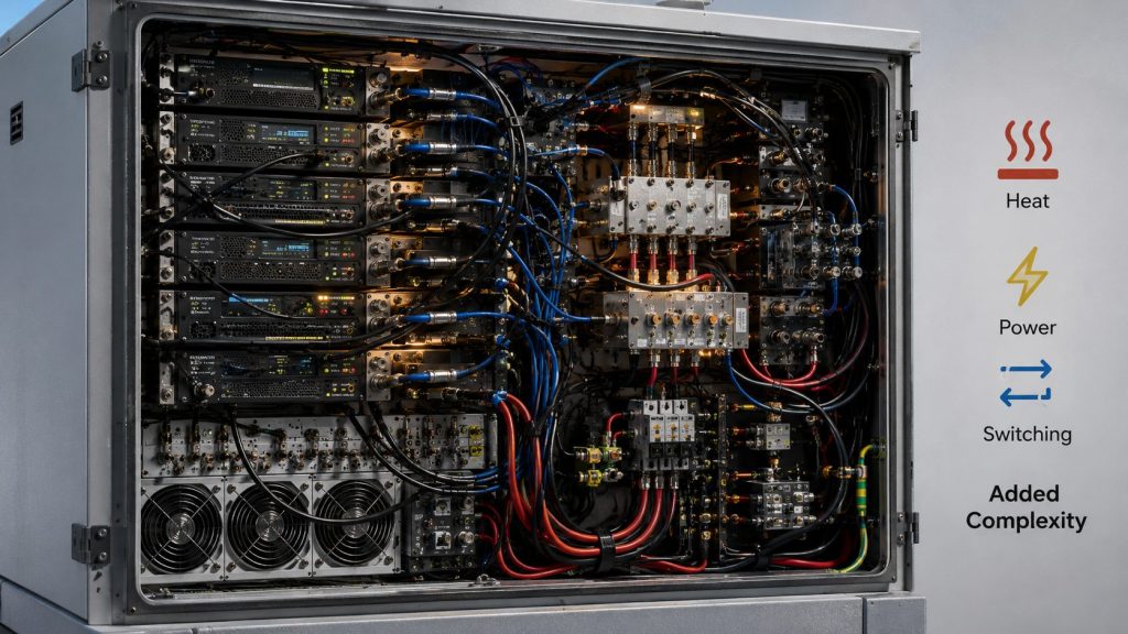
What are the common overlap trade-offs?
Overlap may require wider modules, additional adjacent modules, broader antenna support, more test points, and clearer control decisions. None of these are free in a real C-UAS cabinet.
Overlap can create issues such as:
- Higher module cost
- Larger cabinet space
- More thermal load
- Higher current demand
- More switch or filter complexity
- Unclear primary module responsibility
- More alarm states
- Wider acceptance testing
- Protected-band control difficulty
- Longer troubleshooting time
Key Takeaway: Overlap becomes a liability when it increases system complexity without proving useful transition coverage.
| Overlap Problem | System Impact |
|---|---|
| Too much shared coverage | More testing without clear value. |
| Unclear module ownership | Operators cannot tell which path is responsible. |
| Extra hardware | Cabinet, power, and heat budgets increase. |
| Protected boundary nearby | Filtering and control requirements become stricter. |
| No overlap test plan | The added band margin cannot be trusted. |
This table helps engineers reject overlap that looks good in procurement but adds little to field readiness.
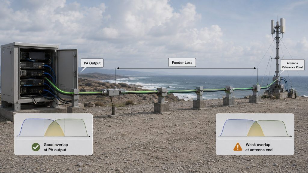
7. What Frequency Overlap Requires Beyond the PA Port
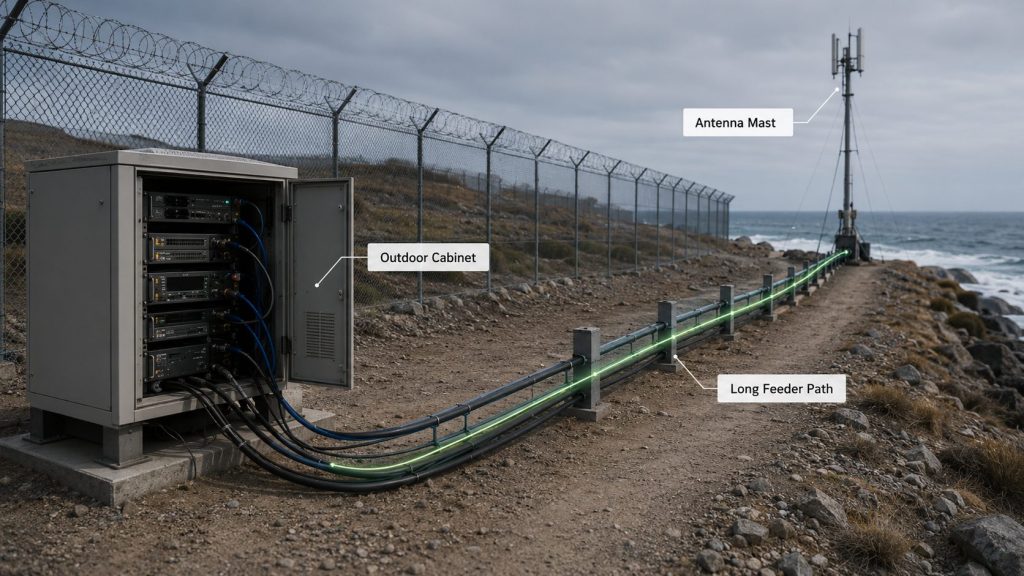
RF Power Amplifier Frequency Range overlap changes value after antennas and feeders are included because the shared PA band only helps when antenna bandwidth, feeder loss, connectors, lightning protection, and VSWR behavior also support that transition zone. PA-port overlap does not prove antenna-end overlap.
Here’s the field reality: border and coastal systems often include long feeders, outdoor connectors, surge protection, tower routing, waterproof joints, and high-power antennas. Each element can change loss and reflection in the overlap zone.
What should be checked beyond the PA port?
The overlap zone should be checked along the installed RF path, not only at the amplifier output connector. This is especially important for high-band paths, where feeder loss and connector quality become more visible.
Check these path items:
- Antenna bandwidth in the overlap zone
- Feeder length and loss
- Connector and adapter count
- Lightning protection device behavior
- VSWR or return loss
- Antenna-port output
- Outdoor sealing and mechanical stress
- High-band cable quality
- Test reference point
Feeder and connector loss can turn paper overlap into weak antenna-end output if the overlap zone is not verified along the installed RF path.
Key Takeaway: Overlap is valuable only when it survives the full RF path from PA output to the antenna-side reference point.
| RF Path Item | Overlap Risk |
|---|---|
| Antenna bandwidth | Shared PA band may exceed usable antenna range. |
| Long feeder | Antenna-end output may fall below margin. |
| Connector transitions | VSWR or reflection may rise at overlap points. |
| Lightning protection | Frequency response may affect the shared band. |
| Undefined reference point | PA-port and antenna-end results may be confused. |
This table helps engineers decide whether overlap remains useful after real installation losses are included.
8. How Should Control Logic Use Overlap Zones?
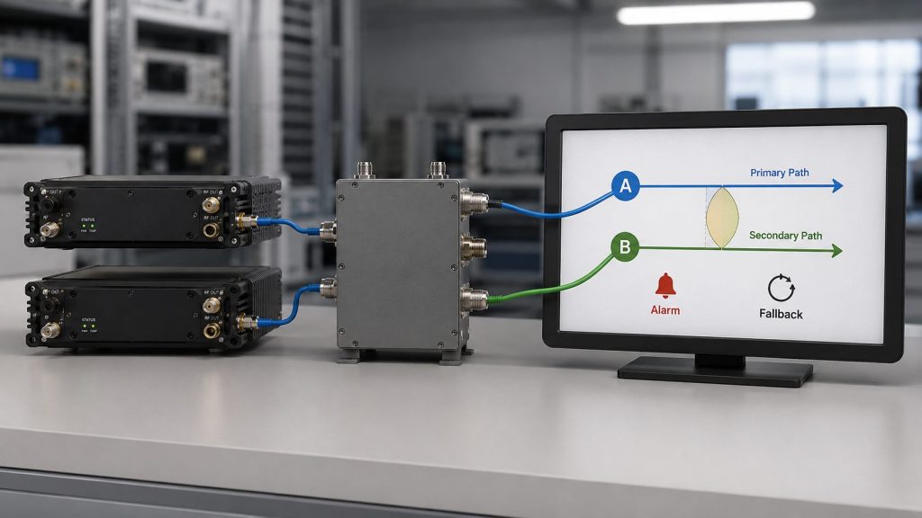
RF Power Amplifier Frequency Range overlap needs control logic because two modules may both be capable of supporting the same transition zone. Without primary and secondary path rules, overlap can create unclear module responsibility, unclear alarm handling, and unclear test results.
The better check is simple: the system should know which module owns the overlap zone under normal conditions and what happens when an alarm, thermal condition, or antenna-path issue appears.
What should the control plan define?
Control logic does not need to become a complex software topic in the RFQ, but it must define enough behavior for integration and acceptance. The overlap zone should not become a random handoff area.
The control plan should define:
- Primary PA path
- Secondary or backup PA path
- Switching boundary
- Enable / disable rule
- Whether simultaneous operation is allowed
- VSWR alarm behavior
- Temperature alarm behavior
- Voltage alarm behavior
- Fallback status
- Test record format
Key Takeaway: Overlap zones should be managed by defined control rules before they can be trusted as transition margin.
| Control Question | Why It Matters |
|---|---|
| Which module is primary? | Prevents responsibility confusion. |
| Is secondary path allowed? | Defines backup value of overlap. |
| Are both modules ever active? | Controls power, heat, and RF path risk. |
| What happens on alarm? | Defines diagnostic and fallback behavior. |
| How is the state recorded? | Supports acceptance and maintenance. |
This table helps engineers turn overlap from a hardware feature into a controlled system function.
9. What Test Evidence Proves Frequency Overlap Works
RF Power Amplifier Frequency Range overlap is actually useful only when both-module data, transition-point tests, hot-state output, antenna-path evidence, VSWR status, control logic, and S/N-linked reports prove that the overlap zone works. A single center-frequency test does not prove overlap.
This is the most important acceptance point: overlap must be tested where the risk lives. That means module edges, transition points, target points inside the shared range, and real RF paths should be included in the evidence package.
What should the overlap test package include?
A credible overlap test package should show whether overlap improves the transition zone under realistic operating conditions. It should not rely on a single module or a single dummy-load reading.
Useful evidence includes:
- Both-module output data
- Overlap start-point test
- Overlap center-point test
- Overlap end-point test
- Target-frequency tests
- Hot-state output
- Duty-cycle condition
- Antenna-path data
- VSWR or reflected-power status
- Control and alarm feedback
- S/N-linked reports
As a source factory for RF Power Amplifier Modules and C-UAS core components, RF SKYPOWER can help integrators review module overlap zones, transition frequencies, antenna paths, feeder loss, VSWR behavior, hot-state output, control feedback, and repeatable test evidence before border or coastal deployment.
Key Takeaway: Overlap should be accepted only when test evidence proves it improves the transition zone under system-level conditions.
| Weak Evidence | Better Evidence |
|---|---|
| Datasheet overlap only | Tested overlap-zone output. |
| One module tested | Both-module or defined primary-path data. |
| Cold-state output only | Hot-state and duty-cycle evidence. |
| PA-port test only | Antenna-path reference data. |
| No control record | Primary / secondary path and alarm evidence. |
This table helps procurement teams decide whether overlap is a real engineering margin or an unsupported claim.
10. How to Define Frequency Overlap in RFQ Documents
RF Power Amplifier Frequency Range overlap should be written into the RFQ as transition zones, target points, module responsibility, antenna path, usable output, VSWR, duty cycle, control logic, and report evidence. A vague sentence such as “overlap required” is not enough.
Here’s the better check: the RFQ should define what problem the overlap is solving. Is it preventing a gap, protecting a band edge, supporting fallback, preparing future expansion, or improving antenna-end margin in a border or coastal installation?
What should the RFQ include?
A strong RFQ should describe the overlap zone as a testable requirement, not a decorative band extension.
Include these items:
- Required RF Power Amplifier Frequency Range
- Module band groups
- Transition frequencies
- Required overlap zones
- Target points inside overlap
- Primary module responsibility
- Secondary path requirement
- Output reference point
- Feeder length
- Antenna path
- VSWR or reflected-power requirement
- Duty cycle
- Hot-state test requirement
- Control logic requirement
- Alarm feedback
- Protected bands
- Report format
- S/N-linked report requirement
- Field acceptance boundary
Before comparing RF Power Amplifier Modules, engineers should check whether adjacent module bands create useful overlap, weak transition zones, or unnecessary cabinet complexity.
Key Takeaway: RFQ documents should define overlap by transition behavior and evidence, not by a generic request for overlapping bands.
| RFQ Item | Why It Matters |
|---|---|
| Overlap zone | Defines where transition margin is required. |
| Target points | Prevents testing only easy frequencies. |
| Module responsibility | Clarifies primary and backup paths. |
| Antenna path | Connects PA overlap to installed RF behavior. |
| Hot-state test | Confirms overlap under duty load. |
| Report evidence | Makes acceptance repeatable. |
This table helps engineering and procurement teams specify overlap in a way suppliers can quote, test, and document.
FAQ
Is frequency overlap always better than no overlap?
No. Frequency overlap is useful only when it creates verified transition margin. If it adds cost, heat, control complexity, and testing burden without improving the transition zone, it may not be worth adding.
How do I know if overlap is enough?
Start with target points, module edge behavior, antenna bandwidth, feeder loss, VSWR, hot-state output, and test evidence. Enough overlap is the amount needed to cover transition uncertainty, not a universal MHz number.
Can overlap prevent frequency gaps between RF PA modules?
Yes, if the overlap zone is tested as usable coverage. Rated frequency ranges can overlap on paper while hidden gaps remain because of weak edge output, antenna mismatch, feeder loss, or hot-state derating.
Should overlap be tested at the PA port or antenna path?
Both may be useful, but antenna-path evidence is more important for field confidence. PA-port overlap does not prove that the overlap remains usable after feeders, connectors, lightning protection, and antennas are included.
What should an overlap RFQ include?
It should include transition zones, target points, primary and secondary module roles, output reference point, antenna path, feeder length, VSWR, hot-state duty, control logic, alarm feedback, and S/N-linked report expectations.
Conclusion
Frequency overlap can be valuable in multi-module RF PA systems, but it is not automatically useful. In border and coastal C-UAS deployments, overlap should be planned only when it creates verified transition margin across module boundaries, band edges, antenna paths, feeder loss, VSWR behavior, hot-state operation, and control logic.
This article showed why paper overlap is not the same as usable overlap. Engineers should evaluate whether the overlap zone prevents real gaps, improves band-edge margin, survives the antenna path, remains stable under heat, and can be controlled and tested as part of the system.
RF SKYPOWER can support overlap-zone review by helping integrators compare rated module overlap with installed RF behavior, feeder loss, antenna match, VSWR status, hot-state output, control feedback, and repeatable reports. Before selecting RF Power Amplifier Modules for border or coastal C-UAS projects, contact us today to review your frequency groups, transition points, overlap zones, antenna paths, feeder length, duty cycle, and S/N-linked test-report expectations.
Useful overlap is measured at the transition zone, not assumed from a frequency table.