


To verify RF Power Amplifier Gain at full power, engineers must compare small-signal gain with target-frequency output, Pout-vs-Pin behavior, current draw, voltage, temperature, VSWR status, and duty-cycle evidence. A clean gain curve at low drive may help early RF comparison, but it does not prove rated output, hot-state stability, antenna-path behavior, or long-duty C-UAS operation.
The central conflict is simple: small-signal gain shows how an amplifier behaves under low-level, low-stress conditions, while full-power verification proves whether the PA module can hold usable output under real operating stress. In a fixed-site low-altitude security system, the RF Power Amplifier Gain number on a datasheet is only meaningful when it is tied to input drive, output power, frequency point, load condition, supply voltage, temperature, duty cycle, and protection status.
This article explains how engineers can verify RF Power Amplifier Gain at full power before approving RF PA modules for fixed-site C-UAS systems, and why small-signal gain should be treated as an early indicator rather than final acceptance evidence.
1. What Small-Signal RF Power Amplifier Gain Shows
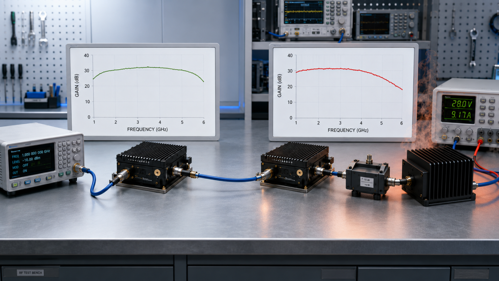
Small-signal gain is only an early indicator because RF Power Amplifier Gain measured at low input drive does not represent the stress level of full-power C-UAS operation. It shows whether the amplifier can increase a weak RF signal across a defined frequency range, but it does not prove how the module behaves near rated output.
Small-signal gain is still useful. It can show whether the module has basic amplification, whether the gain curve is smooth, and whether there are obvious dips across the rated band. The problem starts when this low-stress result is treated as final approval evidence.
What does small-signal gain actually show?
Small-signal gain mainly describes the amplifier’s early frequency response. It can help you screen modules before deeper testing.
A useful small-signal review may show:
- gain trend across the rated frequency range;
- obvious gain dips or abnormal ripple;
- low, center, and high-band response;
- early matching or design issues;
- whether a module deserves full-power testing.
Here’s the engineering point: small-signal gain tells you where to look next, not where to stop.
Where does the interpretation limit appear?
The limit appears because the module is not yet facing high current, high heat, rated output, antenna load, or protection pressure. A fixed-site C-UAS system does not operate as a low-power network analyzer trace; it operates through a full RF chain, usually with cabinets, feeders, antennas, control logic, and long-duty requirements.
When engineers compare RF Power Amplifier Modules, the gain value should be identified as small-signal, full-power, hot-state, or target-frequency evidence before it is used for selection.
Key Takeaway: Small-signal gain is a good screening tool, but it cannot replace full-power proof under C-UAS operating conditions.
| Wrong Assumption | Better Check |
|---|---|
| Smooth small-signal gain proves stable output | Verify target-frequency full-power output |
| High gain means enough antenna-end power | Check output, feeder loss, and load condition |
| One curve proves deployment readiness | Review hot-state and duty-cycle behavior |
| Datasheet gain is acceptance evidence | Request condition-based test data |
This table separates early RF screening from real approval evidence.
2. Why Does Small-Signal Gain Look Better Than Full-Power Gain?
Small-signal gain often looks better than full-power gain because RF Power Amplifier Gain is measured before the amplifier faces compression, heat, current demand, supply droop, or load mismatch. Low input drive keeps the amplifier in an easier operating region, so the curve can look clean even when full-power behavior is more difficult.
At rated output, the same module may need more input drive, draw more current, generate more heat, and work closer to matching and protection limits. That is where the attractive low-level curve can become misleading.
What changes when drive level increases?
As input drive rises, the amplifier may stop increasing output at the same rate. This is where gain compression begins to matter.
Engineers should compare:
- input drive at the PA input connector;
- measured output power at each target frequency;
- calculated gain at rated output;
- current draw during the full-power test;
- temperature and alarm status during operation.
The practical risk is clear: a gain value without drive condition is not enough to predict full-power output.
Why does the curve change under load?
Full-power gain is affected by the full operating environment. The module may behave differently at the low edge, center band, and high edge because each point can have different efficiency, matching, compression, and heat behavior.
For fixed-site Low-Altitude Security & C-UAS EW systems, this matters because the project usually needs stable RF behavior after cabinet integration, not only during a short bench measurement.
Key Takeaway: Small-signal gain looks better because the amplifier has not yet entered the stress conditions that define real C-UAS performance.
| Test Condition | Why It Looks Good | What It May Hide |
|---|---|---|
| Low input drive | Linear behavior | Compression at rated output |
| Short sweep | Low heat buildup | Hot-state gain drift |
| 50Ω bench load | Clean match | Antenna-path VSWR risk |
| Center frequency only | Strongest point | Edge-band weakness |
This comparison shows why a clean early gain curve should lead to deeper testing, not final approval.
3. How to Check RF PA Gain Compression at Full Power
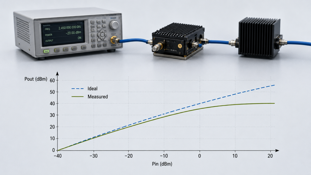
Gain compression changes C-UAS PA output because RF Power Amplifier Gain may decrease as the module approaches rated output. In the small-signal region, a 1 dB input increase may produce nearly a 1 dB output increase, but near full power, output growth can slow down.
This means engineers cannot safely calculate full-power output by applying small-signal gain to a higher input drive. The module may still be working, but it may not deliver the output that the simple calculation predicts.
How does compression create selection risk?
Compression can make a module look stronger on paper than it is in the real system. A supplier may show a strong gain number, but if that number comes from low drive, it does not show how much gain remains at target output.
Check whether the test data includes:
- Pout vs Pin behavior;
- target-frequency output;
- gain at rated output;
- current and voltage during test;
- thermal condition;
- load and VSWR state.
This is where system integrators should pay attention: the useful question is not only “what is the gain,” but “what gain remains at the output level we need?”
How should Pin and Pout be reviewed together?
Input drive and output power should be reviewed as one operating condition, not as two separate datasheet lines. A PA may show a useful gain value at low drive, but that value cannot prove how much output remains when the module approaches rated power.
If input drive is missing, the output number becomes difficult to judge. Engineers cannot tell whether the module reached target output with normal drive reserve, whether it was already close to compression, or whether the result depends on a narrow bench setup. This is why input drive should be checked together with output power before engineers use gain to judge full-power PA behavior.
If the RFQ only asks for gain, the supplier may return a typical low-drive value. If the RFQ asks for Pout vs Pin at target frequencies, the engineer can see where compression begins, how much drive is required, and whether enough operating margin remains.
| Evidence Type | Weak Version | Better Version |
|---|---|---|
| Gain data | Typical gain only | Gain at target output |
| Output data | One watt screenshot | Pout vs Pin curve |
| Frequency data | Center point only | Low, center, high, target points |
| Test condition | Not stated | Drive, load, supply, temperature stated |
This table helps procurement teams request evidence that RF engineers can reproduce.
4. What RF Power Amplifier Gain Flatness Can Hide
Small-signal gain flatness can hide weak bands because RF Power Amplifier Gain may remain smooth at low drive while full-power output, efficiency, heat, and compression change unevenly across the band. A flat low-level curve does not guarantee flat output at rated power.
This is especially relevant in wideband C-UAS PA selection. A module may look stable from a small-signal sweep, but certain points may lose margin during full-power operation, especially near band edges or high-efficiency stress points.
What is the difference between gain flatness levels?
Small-signal gain flatness shows low-drive frequency response. Full-power gain flatness shows how the amplifier behaves when it is delivering useful RF output under real load and thermal conditions.
RF Power Amplifier gain flatness becomes more meaningful when it is reviewed together with output flatness, efficiency, current, temperature, and VSWR behavior under full-power conditions.
The better check is simple:
- compare small-signal sweep with full-power sweep;
- test low edge, center, high edge, and project target points;
- record output and current at each point;
- repeat after warm-up;
- check alarm status during the test.
What does a weak band look like?
A weak band may not appear as a dramatic failure. It may show as lower output, higher current, more heat, earlier compression, or reduced VSWR margin at one frequency range.
In fixed-site C-UAS integration, that weak band can become a coverage gap, a calibration burden, or an acceptance dispute. The module may pass a low-power curve test but fail the project’s real operating target.
Key Takeaway: Small-signal gain flatness is useful, but weak C-UAS bands must be found with full-power output and hot-state evidence.
| Smooth Low-Drive Result | Possible Full-Power Problem |
|---|---|
| Flat small-signal gain | Uneven output at rated power |
| No visible gain dip | Higher current at one band |
| Good center-band response | Weak edge-band output |
| Clean room-temperature curve | Hot-state drift after warm-up |
This table shows why full-power flatness is a different approval question from small-signal flatness.
5. Why Are Band Edges More Misleading in Gain Tests?
Band edges are more misleading in RF Power Amplifier Gain tests because they may show acceptable small-signal gain while losing full-power output, thermal margin, or VSWR stability at rated operation. The edge can look usable in a low-level sweep but become weak when the system needs real output.
This does not mean every band edge is unsafe. It means edge frequencies need better proof, especially when the C-UAS project places target frequencies near the lower or upper boundary of a wideband module.
What makes edge frequencies harder?
Band edges often sit closer to matching, efficiency, and output-network limits. At low drive, the module may still show a usable gain curve. At high drive, the same point may require more input, draw more current, run hotter, or move closer to protection limits.
For a 300–2700MHz RF Power Amplifier Module, engineers should not assume that low, center, and high points behave the same. The same logic applies to high-band paths such as a 2000–6000MHz RF Power Amplifier Module.
What should be tested near the edge?
Edge testing should be treated as a project-specific requirement, not a generic datasheet line.
Ask for:
- full-power output at edge target points;
- gain at the required output level;
- current draw by frequency;
- temperature after warm-up;
- VSWR or reflected-power status;
- protection alarm record;
- repeatability across units if buying in batches.
Here’s the field reality: a band edge that passes early screening can still become the first place where fixed-site performance becomes unstable.
Key Takeaway: Band-edge gain must be validated at full power because small-signal curves can make edge frequencies look safer than they are.
| Band Position | Small-Signal Risk | Full-Power Check |
|---|---|---|
| Low edge | Gain looks acceptable | Output and current test |
| Center band | May look strongest | Do not use as only proof |
| High edge | Edge loss hidden | Hot-state output test |
| Project target point | Not always tested | Add to RFQ test list |
This table helps engineers avoid approving a wideband module from center-band data alone.
6. How Do Duty Cycle and Hot-State Operation Change Gain?
Duty cycle and hot-state operation change RF Power Amplifier Gain because full-power C-UAS use creates heat, current stress, and protection-margin changes that small-signal tests do not expose. A module may start strong and then shift after warm-up.
For fixed-site low-altitude security, the useful number is not only the gain measured at room temperature. The useful number is the gain and output that remain after the module has reached the thermal state expected in the installed cabinet.
Why does duty cycle matter?
Duty cycle defines how long the module must sustain RF output. Higher duty creates less recovery time, more heat buildup, and more pressure on the DC supply and cooling path.
A long-duty review should include:
- output power over time;
- gain after warm-up;
- heatsink or case temperature;
- module-terminal voltage;
- current draw;
- alarm and protection status;
- low, center, high, and target frequency points.
This is where the startup number can mislead you. A module that reaches target output for a short test may not hold it in a fixed-site cabinet.
What does hot-state gain reveal?
Hot-state gain shows whether the amplifier remains predictable after temperature has stabilized. It may reveal frequency-dependent drift that was invisible during a room-temperature small-signal sweep.
In a fixed rooftop C-UAS cabinet, several PA channels may operate near the same thermal window, so the gain that looked stable during a short bench sweep may shift after warm-up. In an airport perimeter or rooftop installation, cabinet airflow, sun exposure, multiple active PA channels, feeder routing, and antenna load can all make hot-state data more relevant than the first cold reading.
Key Takeaway: Full-power gain should be judged after warm-up, not only from a cold small-signal sweep.
| Test State | What It Shows | What It Misses |
|---|---|---|
| Cold small-signal sweep | Early gain curve | Heat and duty stress |
| Short full-power burst | Startup output | Long-duty drift |
| Hot-state sweep | Stable operating behavior | Requires controlled setup |
| Installed-path retest | Field relevance | Needs system access |
This table helps define whether a test result represents the actual fixed-site operating state.
7. How Do Supply Voltage and Current Affect Full-Power Gain?
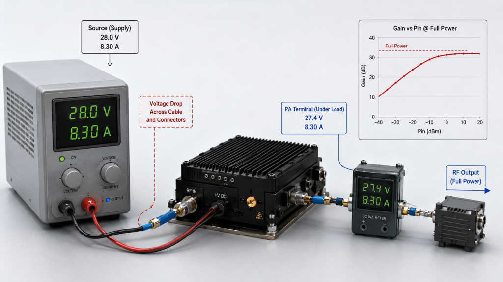
Supply voltage and current affect full-power RF Power Amplifier Gain because rated output requires real DC power reserve at the module terminals. Small-signal testing draws little current, so supply weakness may remain invisible until the PA is driven near full output.
In multi-module fixed-site cabinets, voltage drop, shared rail loading, cable gauge, connector resistance, grounding, ripple, and current limit can all change RF behavior. A gain curve cannot show this unless the electrical condition is recorded.
What DC details should be reviewed?
The DC path must be checked under RF load, not only at idle. A bench supply reading does not prove the voltage at the PA module when current demand rises.
Review these items:
- supply voltage at the source;
- voltage at module terminals;
- current at target output;
- simultaneous module loading;
- cable and connector voltage drop;
- ripple or instability;
- fuse and protection behavior;
- alarm feedback during load.
The selection risk appears here: a module may be blamed for low output when the real problem is DC delivery.
Why does current vary by frequency?
Current demand can change by frequency because efficiency and matching are not identical across the band. A point that looks normal in small-signal gain may require more DC power during full-power operation.
For wideband modules, current and temperature should be recorded along with gain and output at each target point. Without that data, an engineer cannot tell whether the weak result comes from RF design, drive level, thermal load, or power delivery.
Key Takeaway: Full-power gain evidence is incomplete unless voltage and current are recorded under the same condition as the RF output test.
| DC Condition | Possible RF Symptom | Better Check |
|---|---|---|
| Voltage sag | Lower output | Measure at PA terminals |
| Current limit | Early compression | Test rated output current |
| Shared rail overload | Channel interaction | Test simultaneous load |
| Poor ripple control | Output instability | Check DC quality under RF load |
This table helps engineers connect RF symptoms with power-chain causes instead of guessing.
8. How to Verify RF Power Amplifier Gain Evidence
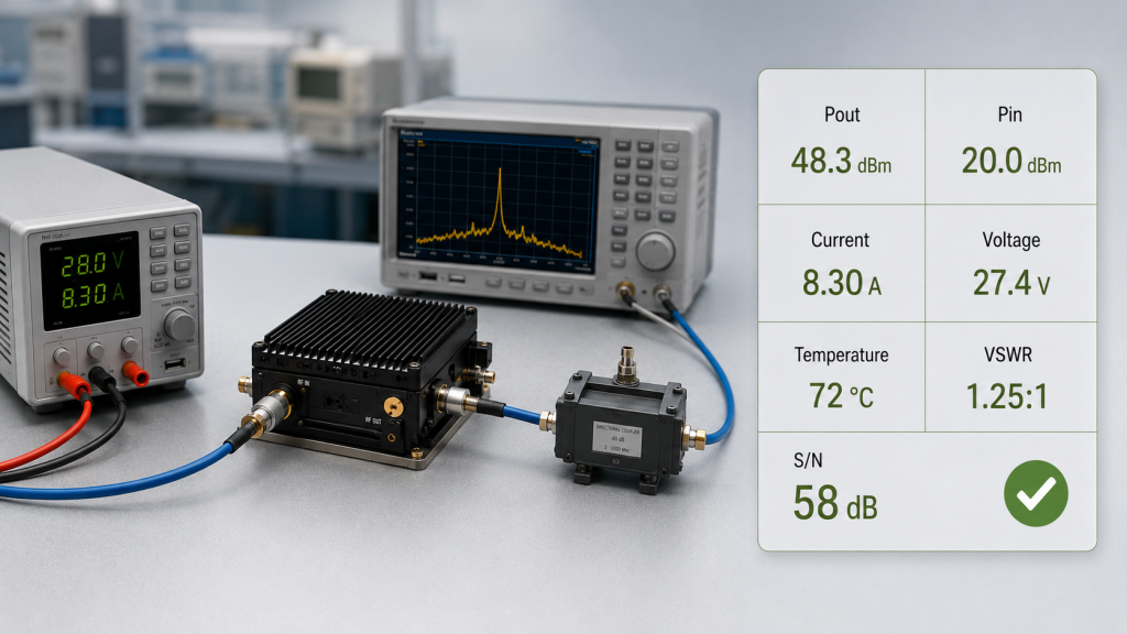
Full-power PA performance should be proven by target-frequency output, Pout-vs-Pin behavior, compression data, current draw, voltage, temperature, VSWR status, duty condition, and S/N-linked reports, not by RF Power Amplifier Gain alone. A gain number without test condition is too weak for fixed-site C-UAS approval.
The evidence should let another engineer understand how the result was produced. If the test cannot be repeated, compared, or connected to the installed RF chain, it is not strong enough for procurement approval.
What should a full-power report include?
A useful report should connect RF, DC, thermal, load, and protection data in the same operating state.
Ask for:
- target frequency point;
- input drive level;
- measured output power;
- calculated full-power gain;
- Pout vs Pin or compression behavior;
- voltage at PA terminal;
- current at target output;
- case, heatsink, or baseplate temperature;
- duty condition and test duration;
- load condition or antenna-path reference;
- VSWR or reflected-power status;
- alarm or protection status;
- serial-number-linked data.
Here’s the practical test: the report should answer how the PA reached the output, not only whether it reached it once.
Why is serial-number evidence useful?
S/N-linked reports help when a project buys multiple units or must repeat acceptance later. They reduce confusion between sample performance, batch performance, and installed-unit behavior.
As a source factory for RF Power Amplifier Modules and C-UAS core components, RF SKYPOWER can support engineering review by connecting small-signal gain, full-power gain, Pout-vs-Pin behavior, hot-state output, supply current, VSWR status, and repeatable test evidence before fixed-site deployment.
Key Takeaway: Full-power proof must be condition-based, repeatable, and tied to the frequencies and operating state the project will actually use.
| Weak Evidence | Better Evidence |
|---|---|
| Typical gain value | Gain at target output |
| One output screenshot | Pout-vs-Pin and frequency data |
| No thermal condition | Hot-state output record |
| Generic sample report | S/N-linked unit report |
| No load status | VSWR and reflected-power record |
| No DC record | Voltage and current under RF load |
This table turns full-power approval into a repeatable evidence checklist.
9. How to Write RF Power Amplifier Gain Requirements
Engineers should write RF Power Amplifier Gain requirements into the RFQ by tying gain to frequency point, input drive, output target, duty cycle, thermal condition, supply voltage, load condition, and test-report evidence. A request for “high gain” is too vague.
If the RFQ only asks for a gain number, suppliers may answer with typical small-signal data. That may be technically true, but it will not tell you whether the module can hold full-power output in your C-UAS system.
What should replace “high gain required”?
A stronger RFQ should define the operating condition behind the gain requirement.
Include:
- required frequency range;
- target frequency points;
- required output power;
- input drive level;
- gain at target output;
- gain flatness at full-power condition;
- Pout vs Pin data;
- supply voltage and current;
- duty cycle;
- cooling condition;
- load or antenna-path condition;
- VSWR and alarm status;
- report format and S/N requirement.
A practical RFQ sentence would be: “Provide full-power gain and output data at each target frequency under specified input drive, supply voltage, duty cycle, cooling condition, load condition, and alarm-status record.”
How should datasheet gain be questioned?
A datasheet gain value should be treated as a starting point. The buyer should ask whether it is small-signal, typical, full-power, hot-state, or target-frequency data.
An RF Power Amplifier datasheet should make clear whether the listed gain values are tied to output power, drive level, frequency point, supply condition, duty cycle, thermal behavior, and protection status.
Key Takeaway: RFQ gain requirements should define the test condition, not only the desired gain number.
| RFQ Item | Why It Matters |
|---|---|
| Target frequency points | Prevents center-only proof |
| Input drive level | Makes gain calculation meaningful |
| Output target | Links gain to useful RF power |
| Duty and temperature | Shows sustained behavior |
| Supply voltage and current | Confirms DC support |
| VSWR status | Protects antenna-path operation |
| Report format | Reduces acceptance disputes |
This RFQ table helps buyers receive engineering evidence instead of generic datasheet claims.
10. What Factory Review Adds to RF PA Gain Testing
Source-factory review can prevent RF Power Amplifier Gain misreading by separating small-signal gain, full-power gain, compression behavior, hot-state output, antenna-load response, and test-report evidence before PA approval. This is not about making the datasheet look stronger; it is about making the data usable.
For C-UAS integrators, the risk is highest when different teams read the same gain number differently. Procurement may see a strong value, RF engineers may ask for drive condition, and field teams may later discover thermal or load-related behavior that was never tested.
What should the factory help clarify?
A source factory can help clarify whether the gain result belongs to a real approval condition.
The review should connect:
- small-signal gain curve;
- full-power target output;
- input drive requirement;
- compression behavior;
- supply voltage and current;
- hot-state sweep;
- VSWR or reflected-power status;
- duty-cycle condition;
- S/N-linked report;
- mechanical and cooling fit.
Here’s the useful part: the factory review should reduce interpretation risk before the module enters the cabinet.
What final decision should engineers make?
The final decision should not be “which module has the highest gain.” It should be “which module has gain, output, thermal behavior, protection margin, and test evidence that match the deployment condition.”
RF SKYPOWER supports wideband RF modules, CNC housings, copper heat spreading, VSWR / temperature / voltage protection, control feedback, and repeatable report discussions for integrators who need condition-based review before final C-UAS module approval.
Key Takeaway: Source-factory review helps engineers compare small-signal data with full-power evidence before gain misinterpretation becomes a field problem.
| Decision Question | Better Review Path |
|---|---|
| Is gain high enough? | Check gain at target output |
| Is the curve flat enough? | Compare full-power sweep |
| Is the module stable? | Review hot-state and duty data |
| Is the RF path safe? | Check VSWR and alarm status |
| Is the batch repeatable? | Request S/N-linked reports |
This decision table helps turn gain review into a practical approval framework.
FAQ
Can I use small-signal gain to compare RF PA modules?
Yes, but only for early screening. Small-signal gain helps compare low-level frequency response, but it cannot prove full-power output, hot-state stability, compression margin, VSWR behavior, or duty-cycle performance.
What is the best way to verify full-power gain?
The best way is to measure gain at target output under defined input drive, frequency, supply voltage, current, load, temperature, and duty condition. Pout-vs-Pin data is especially useful because it shows compression behavior.
How do I know if gain flatness is misleading?
Gain flatness may be misleading if it only comes from a small-signal sweep. Ask for full-power sweep data across low, center, high, and project target points, especially after warm-up.
What should I check before approving a C-UAS PA module?
Check target-frequency output, full-power gain, input drive, compression behavior, current draw, module-terminal voltage, temperature, duty cycle, VSWR status, alarm feedback, and repeatable test reports.
When should I ask for source-factory review?
Ask for source-factory review before RFQ finalization or sample approval. It is most useful when the project involves wideband modules, fixed-site duty, hot cabinets, multiple PA paths, or target frequencies near band edges.
Conclusion
Small-signal gain is useful, but it is not full-power evidence. It can help engineers screen an RF PA module, find early frequency-response issues, and compare low-level gain curves. It cannot prove rated output, full-power gain flatness, gain compression margin, hot-state behavior, supply stability, VSWR safety, antenna-path response, or long-duty C-UAS performance.
For fixed-site low-altitude security projects, the stronger approval path is clear: compare small-signal gain with full-power target-frequency output, Pout-vs-Pin behavior, current draw, voltage, temperature, duty condition, load state, protection status, and S/N-linked reports.
RF SKYPOWER can help system integrators review RF PA gain data, full-power behavior, wideband module fit, cooling condition, antenna-path risk, protection logic, and report requirements before final module approval. To review your RF module requirements for a fixed-site C-UAS project, contact us today.
Field-ready C-UAS performance starts with measured full-power evidence, not small-signal assumptions.