


Frequency Gaps between RF PA modules should be checked before prison and high-security C-UAS systems are approved, because rated RF Power Amplifier Frequency Range does not always prove continuous module-to-module coverage. A cabinet may list several PA modules across low, mid, and high bands, yet still leave weak transitions at module boundaries, filter roll-off zones, antenna-band limits, switching points, or untested edge frequencies.
Avoiding these gaps requires more than adding module frequency ranges into one table. Engineers need to verify where one PA band hands off to the next, whether enough overlap exists, whether filters and switching logic support the transition, whether the antenna and feeder path remain usable, and whether hot-state test evidence proves the boundary points. A multi-band PA system is only as continuous as its weakest transition point.
This article explains how to avoid Frequency Gaps in RF PA modules for C-UAS systems, especially in prisons, correctional facilities, high-security compounds, and fixed perimeter sites. The focus is not broad frequency theory, but a practical engineering workflow: define module boundaries, check overlap zones, review antenna-path continuity, verify protection behavior, and require repeatable test evidence before deployment.
1. What Are RF Power Amplifier Frequency Gaps?
A frequency gap between RF PA modules is a break in RF Power Amplifier Frequency Range continuity where the multi-module system cannot prove usable output, antenna-path support, or test evidence across a required transition. The obvious version is a mathematical gap, such as one module ending at 1200MHz while the next starts at 1500MHz. The more dangerous version is a hidden gap where the table appears continuous, but the system does not remain usable at the boundary.
Here’s the engineering point: a gap is not only an empty space between two rated bands. It can also be a weak transition where output, gain, filtering, antenna matching, VSWR behavior, thermal stability, switching logic, or acceptance evidence does not remain continuous.
What Types of Gaps Should Engineers Identify?
Engineers should separate obvious gaps from hidden system gaps. This helps the team avoid treating a clean frequency table as proof of real coverage.
Common gap types include:
- Rated-band gaps between modules
- Weak output near module band edges
- Filter transition-band loss
- Antenna-band discontinuity
- Feeder and connector loss at high frequencies
- Switching or control-logic boundary errors
- Untested transition or overlap points
The individual RF Power Amplifier module frequency range defines each module’s rated window, but the real gap review begins where one rated window hands off to the next.
Why Does This Matter Before Procurement?
Once the cabinet layout, module set, filters, switching paths, and antenna scheme are approved, a gap becomes harder to fix. The project may need a different PA band, additional overlap, revised filter design, new antenna coverage, or repeated testing.
Key Takeaway: A frequency gap is any unverified or weak transition in the usable RF chain, not only a blank space between two numbers.
| Gap Type | Where It Appears | Better Check |
|---|---|---|
| Rated-band gap | Between module labels | Compare band boundaries |
| Edge-output gap | Near module high or low end | Request edge-frequency data |
| Filter gap | Transition band | Check path response |
| Antenna gap | Installed antenna range | Verify antenna-port behavior |
| Control gap | Switching boundary | Confirm module assignment |
| Evidence gap | Untested point | Require report data |
This table helps engineers treat frequency gaps as a system-level risk instead of a simple catalog issue.
2. Why Do Gaps Matter More in Prison C-UAS Sites?
Frequency gaps matter more in prison and high-security C-UAS sites because RF Power Amplifier Frequency Range discontinuity can become a perimeter weak point, a contraband-delivery window, or an acceptance dispute. These sites are usually fixed, long-duty, perimeter-defined, and sensitive to both external drone threats and internal communication protection. A small unverified transition can matter more here than in a temporary event site.
The practical risk is clear: a prison system may work well across several bands and still leave one transition zone weak. For a high-security perimeter, that weak zone is not only a performance detail; it can become a planning and responsibility problem.

What Makes This Scenario Different?
Correctional and high-security facilities often need persistent coverage, clear perimeter boundaries, controlled RF behavior, and traceable acceptance records. They may also have internal radio, alarm, access-control, patrol, and facility communication systems that must be protected.
For correctional facility security systems, module transitions should be reviewed as part of perimeter coverage planning, because a weak handoff between PA bands can become a site-level security gap.
Important site conditions include:
- Fixed perimeter zones
- Long-duty operation
- Limited maintenance windows
- High consequence of missed coverage
- Internal communication protection
- Clear acceptance responsibility
- Repeatable test requirements
Why Is “Full Coverage” Not the Right Phrase?
“Full coverage” can be misleading if it means uncontrolled output everywhere. A better goal is verified, site-specific RF coverage with clear exclusions, protected internal bands, and documented operating boundaries.
Key Takeaway: In high-security sites, frequency continuity must be verified without ignoring internal communication boundaries or site-specific compliance limits.
| Site Condition | Gap Risk | Better Requirement |
|---|---|---|
| Prison perimeter | Local weak transition | Boundary-point evidence |
| Internal radios | Over-coverage risk | Protected band notes |
| Long-duty operation | Thermal drift | Hot-state checks |
| Limited maintenance | Late redesign cost | Early RFQ clarity |
| High-security acceptance | Responsibility dispute | S/N-linked evidence |
This table shows why frequency gap review belongs in the design phase, not only in final testing.
3. What Rated RF PA Bands Hide Frequency Gaps?
Rated RF PA bands can hide frequency gaps because RF Power Amplifier Frequency Range labels do not prove that output, filtering, switching, antenna matching, and hot-state behavior remain usable at module transitions. A multi-band cabinet may show 300–1200MHz, 1200–2700MHz, and 2000–6000MHz on paper, but the actual transition zones may still be weak or untested.
This is where system integrators should pay attention: a band list is a useful shortlist, not a continuity guarantee. The most important risk is not always an obvious missing interval; it is the assumption that adjacent ranges behave perfectly at their edges.
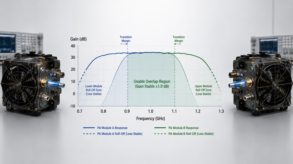
Why Do Band Edges Need More Attention?
Module centers are often easier to optimize and easier to demonstrate. Edges may show output drop, gain ripple, lower efficiency, higher heat, VSWR sensitivity, or reduced repeatability.
Check these boundary conditions:
- Low edge output
- High edge output
- Gain flatness near transition points
- Current and efficiency shift
- Temperature after warm operation
- Load and VSWR condition
- Test reference point
A 300–1200MHz RF Power Amplifier module should not be judged only by its rated band; engineers should also check how its upper edge connects to the next PA band.
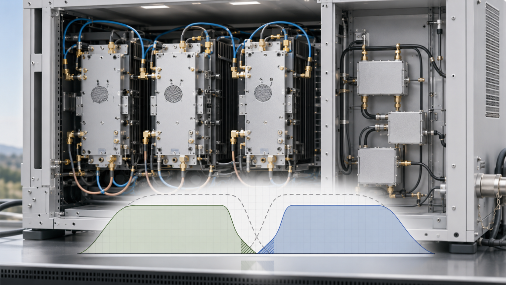
Why Is Overlap Not Automatically Safe?
Overlap helps only when it is usable overlap. If two modules overlap on paper but neither has stable hot-state output, correct filtering, antenna support, or report evidence in that zone, the overlap does not remove the gap risk.
Key Takeaway: A clean frequency table can hide weak transitions unless edge behavior and overlap evidence are checked.
| Common Assumption | Hidden Risk | Better Check |
|---|---|---|
| Bands touch, so coverage is continuous | Edge output may drop | Test transition points |
| Overlap exists, so gap is solved | Overlap may be untested | Verify both sides |
| Datasheet range proves field range | Antenna path may differ | Check installed RF chain |
| Center data is enough | Edges may behave worse | Request band-edge data |
This table helps procurement teams avoid approving a multi-module plan from labels alone.
4. How to Find RF Power Amplifier Frequency Gaps?
Frequency gaps usually appear where RF Power Amplifier Frequency Range meets another system boundary: module band edges, filter transition zones, switch or combiner paths, antenna limits, control-logic boundaries, or untested frequency points. They are often created by the interaction of parts, not by one failed component.
Here’s the field reality: a PA module can cover a frequency while the selected RF path does not. That is why gap review must include more than the PA datasheet.
Which Parts of the System Create Gap Risk?
A useful gap audit should move from the module outward through the cabinet, RF path, antenna path, and test record.
Typical gap sources include:
- Module A high edge
- Module B low edge
- Filter roll-off zone
- Switch matrix boundary
- Combiner or splitter frequency response
- Cable and connector path
- Lightning protector or feedthrough
- Antenna band limit
- Controller band assignment
- Missing test record
A multi-band cabinet becomes easier to evaluate when each RF Power Amplifier module is checked not only as a standalone unit, but also as part of a handoff between adjacent bands.
Why Are Missing Test Points a Gap?
For engineering approval, an untested transition is an unknown zone. If the system depends on that zone, the absence of data should not be treated as pass evidence.
Key Takeaway: Frequency gaps usually appear at transitions between modules, paths, antennas, controls, and evidence—not only inside a PA module.
| System Area | Gap Mechanism | Review Method |
|---|---|---|
| Module edge | Output or gain drop | Edge-point test |
| Filter path | Roll-off loss | Path response check |
| Switch logic | Wrong module assignment | Control-state review |
| Combiner path | Uneven response | Full-path measurement |
| Antenna | Band or matching limit | Antenna-port test |
| Report | Missing frequency point | Acceptance checklist |
This table gives engineers a practical map for finding gaps before field deployment.
5. How to Close RF PA Frequency Gaps with Overlap?
Enough RF PA module overlap is the amount needed to protect RF Power Amplifier Frequency Range continuity at transition points while avoiding unnecessary hardware, heat, control complexity, and protected-band conflict. The correct overlap should be based on transition risk, target link location, filter roll-off, antenna bandwidth, thermal behavior, and acceptance evidence—not a fixed MHz number alone.
The better check is simple: overlap should give the system room to avoid placing critical frequencies at the weakest edge of a module. It should not be used as a decorative number in a datasheet comparison.
What Should Define Overlap Margin?
Overlap margin should come from the specific system design and the frequency points the project must protect. It should also account for internal protected bands and compliance boundaries.
Review these conditions:
- Target links near module boundary
- Module edge output and gain
- Filter transition width
- Antenna usable bandwidth
- Hot-state output stability
- Switching or control logic
- Simultaneous or sequential operation
- Protected internal communication bands
- Future expansion requirements
- Test report coverage
A 300–1700MHz RF Power Amplifier module may reduce low-to-mid band gaps, but transition points and overlap zones still need output, thermal, and antenna-path verification.
When Can Wider Modules Help?
Wider modules can reduce the number of transitions, but they also raise questions about output flatness, efficiency, heat, antenna match, and full-band evidence. They are not automatic gap solutions.
Key Takeaway: Overlap is useful when it is measurable, controlled, and supported by antenna and test evidence.
| Overlap Decision | Good Reason | Risk If Misused |
|---|---|---|
| Add overlap | Critical point near edge | More complexity |
| Use wider module | Reduce transitions | Heat or flatness issue |
| Split bands | Cleaner control | More paths to verify |
| Protect internal band | Site safety | Coverage planning limits |
| Test overlap | Prove continuity | More acceptance work |
This table helps engineers define overlap as an engineering margin, not a generic rule.
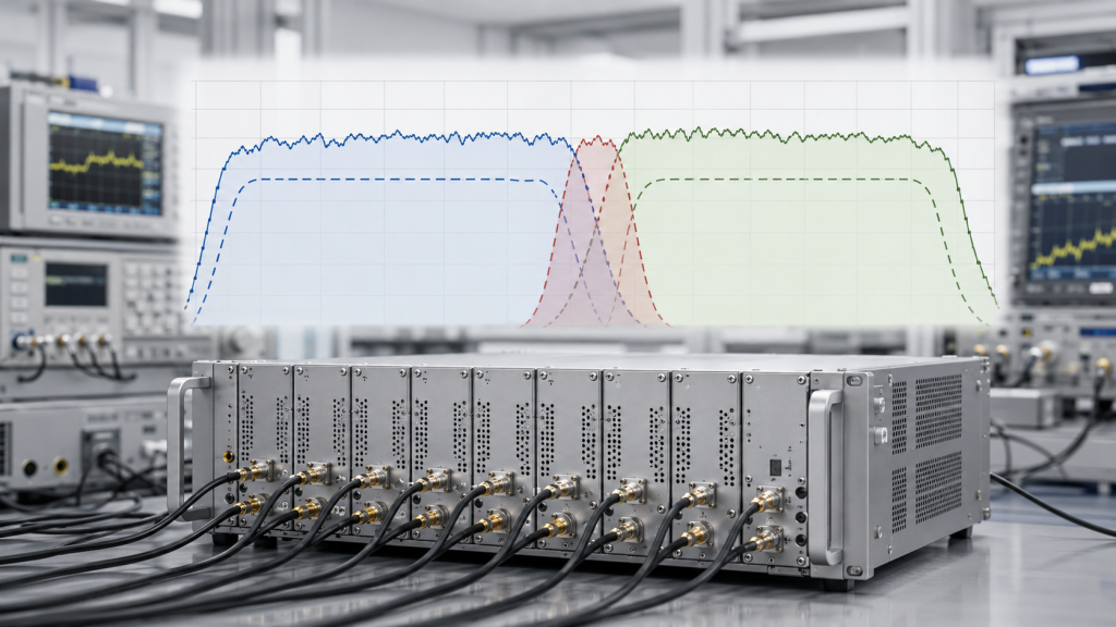
6. Why Can Filter Roll-Off and Switching Logic Create Gaps?
Filter roll-off and switching logic can create hidden gaps because RF Power Amplifier Frequency Range may cover a frequency while the selected RF path, transition band, or control state does not deliver usable output. In a multi-module cabinet, PA modules rarely connect directly to antennas without other components. Filters, switches, combiners, isolators, couplers, feedthroughs, and control boards all shape the final path.
The selection risk appears here: the PA may be correct, but the cabinet path may be wrong at the transition. If this is not checked early, the project team may blame the module when the real issue is filter or switching alignment.

How Does Filter Roll-Off Create a Weak Zone?
Filters do not start or stop perfectly at a single frequency. They have transition zones. If module A is weak near its high edge, filter A is rolling off, module B is not yet stable, and filter B is still entering its pass region, the system can create a hidden weak zone.
Check these items:
- Filter passband
- Filter transition width
- PA edge frequencies
- Switching threshold
- Combiner path response
- Insertion loss by frequency
- Protection-state behavior
A RF Power Amplifier module can simplify some multi-band coverage plans, but engineers still need to verify high-end output, filter behavior, and cabinet thermal margin.
How Does Switching Logic Add Risk?
Control logic decides which module or path is active near a boundary. If the boundary is unclear, a frequency may fall between two logic states or be assigned to a path with weaker RF behavior.
Key Takeaway: Hidden gaps often come from the cabinet path and control state, not only from PA module coverage.
| Hidden Gap Source | What Can Happen | Better Control |
|---|---|---|
| Filter roll-off | Transition attenuation | Align filter and PA bands |
| Switch boundary | Wrong path selected | Define control ownership |
| Combiner response | Uneven output | Measure full path |
| Protection state | Output reduction | Record alarms |
| Control fallback | Band not enabled | Test failure modes |
This table helps teams review transition behavior inside the cabinet before approving the full system.
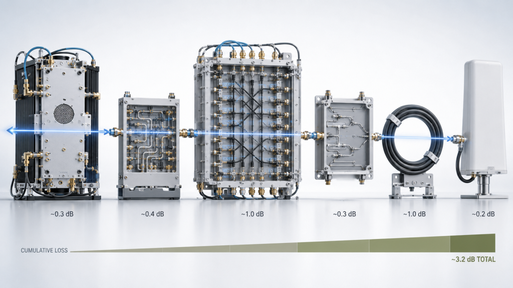
7. How Do Antennas and Feeders Turn Gaps into Blind Spots?
Antennas and feeder paths can turn small module gaps into field blind spots because RF Power Amplifier Frequency Range continuity at the cabinet does not guarantee antenna-end continuity at the prison perimeter. A weak transition frequency may lose more margin after antenna mismatch, cable loss, connectors, site obstruction, and VSWR protection are included.
Here’s the engineering point: module continuity is not the same as field coverage. The frequency that looks acceptable at the PA port may become weak after it passes through the installed RF chain.
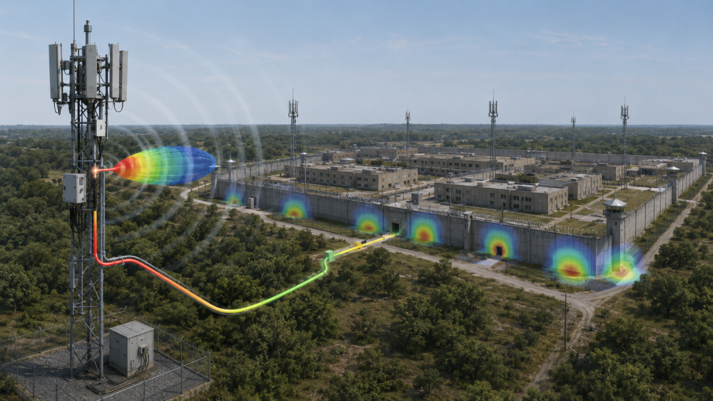
What Field Factors Amplify Module Gaps?
Prison and high-security facilities often include walls, buildings, towers, metal structures, gates, patrol routes, and multiple antenna sectors. These site features make antenna-path verification important.
Review these field factors:
- Antenna working band
- Antenna gain and direction pattern
- Polarization and mounting height
- Feeder length
- Connector and adapter count
- Lightning protector or outdoor interface
- VSWR at transition frequencies
- Nearby walls or metal structures
- Antenna-port reference point
A RF Power Amplifier module should be checked at its low-end transition and high-end operating points because high-band path loss can expose hidden coverage gaps.
Why Should Boundary Frequencies Be Tested On-Site?
Boundary frequencies are where multiple risks meet: PA edge behavior, filter response, antenna match, and feeder loss. These are exactly the points most likely to look acceptable in the cabinet but weaker at the perimeter.
Key Takeaway: Small module gaps can become real RF blind spots when the antenna path and site environment reduce already-tight margin.
| Field Factor | How It Amplifies Gap Risk | Better Check |
|---|---|---|
| Antenna mismatch | Raises reflected power | VSWR at transition |
| Long feeder | Reduces antenna-end output | Path-loss review |
| Building obstruction | Uneven perimeter coverage | Sector check |
| High-band path | More sensitive loss | Antenna-port test |
| Outdoor interfaces | Added transitions | Installed-path evidence |
This table helps teams connect cabinet-level frequency continuity to real perimeter behavior.
8. How to Prove RF PA Frequency Gaps Are Closed?
Critical frequency gaps can be ruled out only when RF Power Amplifier Frequency Range transitions, overlap zones, antenna-path output, hot-state behavior, protection status, and S/N-linked test data are checked under the same acceptance boundary. A center-frequency power number is not enough. A module datasheet is not enough. The report must cover the weak points where gaps are most likely to appear.
The better check is simple: test the transition, not only the center. If the project depends on multi-band continuity, the boundary points deserve direct evidence.
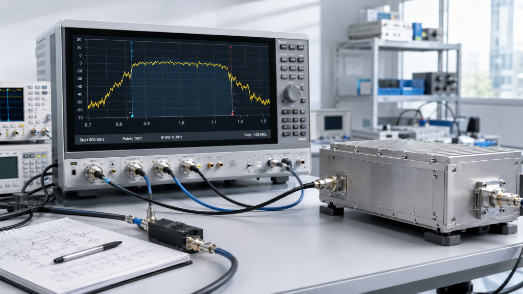
What Should the Report Include?
A useful report should show the conditions that decide whether the transition is usable. It should not only state that a module passed a generic power test.
Request evidence for:
- Module low-edge and high-edge points
- Adjacent module transition frequencies
- Overlap-zone behavior
- PA-port and antenna-path reference points
- Hot-state output
- 28V supply voltage and current
- VSWR or reflected-power status
- Temperature, voltage, or protection alarms
- S/N-linked unit data
- Test setup and load condition
Band-edge performance becomes more important when two RF PA modules meet at a transition frequency and both edges must remain usable.
How Does S/N-Linked Evidence Help?
In high-security systems, sample data is not always enough. Each delivered unit may need traceable evidence that its relevant transition points were checked under defined conditions.
Even when no critical gap is found, RF power consistency still matters across channels, antenna paths, and thermal states because continuous frequency coverage does not automatically mean balanced usable output.
Key Takeaway: A gap-free claim is credible only when transition points and overlap zones are documented, repeatable, and tied to the delivered units.
| Evidence Type | What It Proves | Weak Alternative |
|---|---|---|
| Transition-point data | Boundary continuity | Center-point test |
| Overlap-zone data | Usable module handoff | Rated overlap only |
| Hot-state result | Long-duty stability | Cold short test |
| Protection status | Safe RF behavior | Output only |
| S/N-linked report | Unit traceability | Generic sample data |
This table helps procurement and engineering teams request the right proof before acceptance.
9. What RFQ Data Prevents RF PA Frequency Gaps?
Engineers should write frequency gap requirements into the RFQ by defining RF Power Amplifier Frequency Range groups, module boundaries, allowed or forbidden gaps, overlap expectations, transition-point tests, antenna-path references, protected internal bands, and report evidence before approval. A request such as “need 300MHz–6GHz coverage” is too broad for a high-security C-UAS cabinet.
This is where many problems begin: if the RFQ does not define transition boundaries, the supplier may build a module list that looks complete but does not prove continuity. The buyer then discovers the gap only after integration.

What Should the RFQ Say?
The RFQ should be specific enough to guide design, quotation, and acceptance. It does not need to become a legal document, but it should remove the most dangerous assumptions.
Include these items:
- Required frequency groups
- Target link frequency points
- Module band boundaries
- Allowed or forbidden frequency gaps
- Minimum overlap expectation
- Transition-point test requirement
- PA-port or antenna-port reference
- Antenna-path assumption
- Duty cycle and cabinet thermal condition
- VSWR or reflected-power status
- Control logic for transition zones
- Protected internal communication bands
- S/N-linked report requirement
- Field acceptance boundary
For broader Low-Altitude Security & C-UAS EW systems, frequency range should be judged by system-level continuity, not only by individual module datasheets.
What Is a Better RFQ Sentence?
A weak RFQ says: “Need full-band C-UAS PA coverage.” A better RFQ defines module groups, transition frequencies, overlap zones, output reference point, antenna path, protected internal bands, duty cycle, and test evidence for each boundary.
Key Takeaway: A clear RFQ makes frequency gap risk visible before the system is built.
| RFQ Item | Why It Matters | Risk If Missing |
|---|---|---|
| Module boundaries | Defines transitions | Hidden gap |
| Overlap expectation | Protects edge points | Weak handoff |
| Antenna reference | Defines field output | Test dispute |
| Protected bands | Protects internal systems | Over-coverage |
| Report format | Proves acceptance | Weak evidence |
This table helps engineers turn gap concerns into practical supplier requirements.
10. How Can Source-Factory Support Reduce Gap Risk?
Source-factory support reduces gap risk by connecting RF Power Amplifier Frequency Range selection with PA module bands, overlap planning, cabinet integration, protection feedback, thermal design, antenna-path assumptions, and repeatable test evidence before final C-UAS deployment. Frequency gaps are not solved by buying more modules alone. They are reduced by reviewing how the modules connect, how the cabinet routes them, and how the system proves the result.
The final decision point is not “which module covers the list?” It is “which verified multi-band architecture leaves the fewest unknown transition zones while respecting the site boundary?”

What Can a Source Factory Review Early?
A source factory can help engineers review module boundaries before the cabinet design becomes difficult to change. This is useful when the system includes several PA bands, filters, antennas, and control states.
Early review can include:
- Adjacent module frequency ranges
- Overlap zone strategy
- Boundary-point test plan
- Filter and switching assumptions
- Cabinet thermal limits
- 28V supply behavior
- VSWR and reflected-power protection
- Antenna-path assumptions
- S/N-linked report expectations
As a source factory for RF Power Amplifier modules and C-UAS core components, RF SKYPOWER can help integrators review module band boundaries, overlap zones, antenna-path assumptions, cabinet thermal limits, VSWR behavior, and repeatable test evidence before final approval.
Why Is This Not Just a Product Question?
A module may be correct, but the cabinet plan may still leave a weak transition. RF SKYPOWER supports wideband RF modules, CNC housings, copper heat spreading, VSWR / temperature / voltage protection, and S/N-linked reports, helping prison and high-security C-UAS teams compare rated module bands with verified system-level coverage.
Key Takeaway: Source-factory support is valuable when it reduces unknowns around module transitions, not when it simply adds more wattage or more bands.
| Review Area | Source-Factory Value | Gap Risk Reduced |
|---|---|---|
| Module boundary | Direct band review | Rated-band mismatch |
| Overlap zone | Testable handoff | Weak transition |
| Cabinet thermal path | Heat-state planning | Output drift |
| Protection feedback | Alarm visibility | Hidden derating |
| S/N-linked report | Traceable evidence | Acceptance dispute |
This table shows how engineering support turns a module list into a verifiable multi-band coverage plan.
FAQ
Can a C-UAS system have gaps even if every module has a rated band?
Yes. A system can still have gaps when module edges are weak, filters roll off, antennas do not cover the transition, switching logic is unclear, or the report does not test boundary points.
How much overlap should RF PA modules have?
There is no universal overlap number. The right overlap depends on target frequencies, module edge behavior, filter transition width, antenna bandwidth, hot-state output, protected internal bands, and acceptance evidence.
What should I test to confirm there is no critical frequency gap?
Test module edges, adjacent-module transition frequencies, overlap zones, antenna-path output, hot-state behavior, VSWR or reflected power, protection status, and S/N-linked unit data.
Are wider RF PA modules always better for avoiding gaps?
No. Wider modules can reduce the number of transitions, but they may also increase heat, flatness, antenna, and verification pressure. The better choice is the architecture that can prove usable coverage at required points.
What should a prison C-UAS RFQ include about frequency gaps?
It should define required frequency groups, module boundaries, allowed gaps, overlap zones, transition-point tests, antenna-path references, protected internal bands, duty cycle, and report evidence.
Conclusion
A multi-band C-UAS system should not be approved only because each RF Power Amplifier module has a clean rated frequency range. Engineers should verify module-to-module transitions, overlap zones, filter behavior, antenna-path continuity, hot-state output, protection status, and S/N-linked test evidence before deciding that the system has no critical frequency gaps.
For prison and high-security sites, this review is especially important. The system must support controlled perimeter coverage while also respecting internal communication boundaries and site-specific compliance limits. A small unverified transition can become a weak zone, an over-coverage problem, or an acceptance dispute if it is not defined during RFQ and checked during delivery.
As an RF Power Amplifier module and C-UAS core component source factory, RF SKYPOWER can support prison and high-security projects by reviewing required frequency groups, module transitions, overlap expectations, antenna-path assumptions, cabinet thermal margin, 28V supply behavior, VSWR protection feedback, and S/N-linked test evidence before final module approval. If your team needs to reduce frequency gap risk in a multi-band C-UAS cabinet, you can review your RF module requirements with RF SKYPOWER before the module layout, filter plan, and acceptance boundary become expensive to change.
Reliable C-UAS coverage is built at the transitions, not only inside the rated bands.