











Wideband vs narrowband RF PA architecture selection should begin with the project band plan, not the widest catalog label. A wideband design may reduce hardware fragmentation when several required frequencies can share the same RF path, filtering strategy, antenna plan, and operating conditions. A narrowband design may provide more room to optimize matching, efficiency, thermal margin, and output behavior around fixed critical bands, but that advantage must be confirmed by comparable test data.
Before choosing among those architectures, the project should complete the broader RF power amplifier module selection workflow for signal drive, usable output, duty cycle, 28 V DC, RF-path, control, protection, and approval evidence.
RF Power Amplifier Modules should therefore be evaluated as parts of a defined RF architecture, not as isolated bandwidth and wattage labels.
Before choosing wideband, narrowband, or mixed architecture, the integrator must define:
- which frequencies are fixed;
- which frequencies may change;
- which bands carry the highest acceptance risk;
- which signals may operate simultaneously;
- where the required RF power will be measured;
- what DC, thermal, antenna, and cabinet limits apply.
For some C-UAS systems, a wideband platform provides the clearest integration path. For others, dedicated narrowband paths protect margin at the most critical frequencies. Many projects are better served by a mixed structure that assigns different frequency groups to different RF paths.
1. Why Bandwidth Alone Cannot Decide the RF PA Architecture
A listed frequency range only indicates nominal operating coverage. It does not prove that every frequency inside that range will provide the same output, gain, efficiency, thermal behavior, or mismatch tolerance after installation.
A module labeled 300–2700 MHz may overlap several target links, but its project value still depends on:
- output at the actual operating frequencies;
- gain and output variation across the assigned range;
- feeder, connector, filter, and bulkhead losses;
- antenna matching at each required frequency;
- DC voltage and current under RF load;
- cabinet airflow and hot-state behavior;
- reflected-power and protection response;
- simultaneous or sequential operating modes.
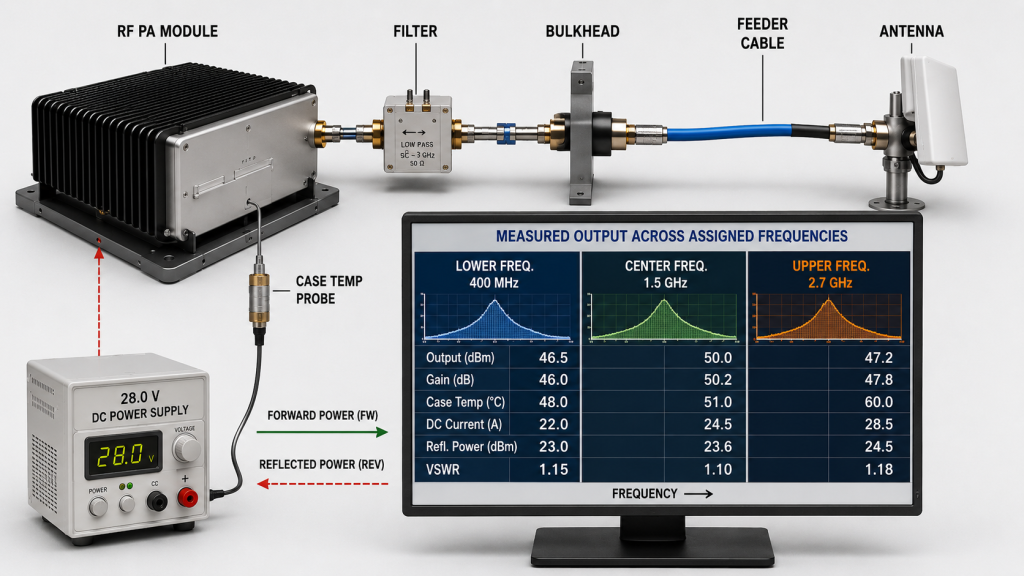
The first step is therefore not to compare module labels. It is to map target links to RF PA frequency coverage and separate the project frequencies into four groups:
- Fixed critical frequencies
- Secondary frequencies
- Possible future frequencies
- Frequencies or channels that may operate simultaneously
The same frequency list can lead to very different architectures.
A project with two fixed, acceptance-critical bands may benefit from dedicated narrowband paths. A project with several changing bands may justify a wider common platform. A project with fixed priority channels plus uncertain future coverage may require a mixed structure.
The required output reference plane can also change the answer. A PA may meet its rating at the module output connector but leave insufficient margin after filters, connectors, feeder cable, and antenna mismatch are included.
Nominal bandwidth is therefore only one input. The final architecture must be based on usable performance at defined frequencies and under defined system conditions.
2. What Wideband, Narrowband, and Mixed Architectures Actually Mean
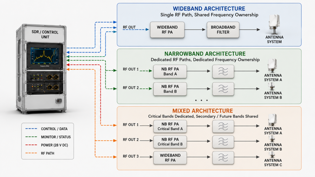
The difference between wideband and narrowband architecture is not only the frequency range printed on the module. It is how the project assigns frequencies, RF paths, antennas, filtering, control, and acceptance responsibility.
Wideband RF PA architecture
A wideband architecture assigns a relatively broad group of required frequencies to one common PA platform or RF path.
The design assumes that acceptable output, thermal behavior, protection margin, and control performance can be maintained across the assigned frequency range.
This approach may reduce hardware count when:
- several frequencies can share one RF path;
- one antenna or antenna group can support the assigned range;
- filtering can be consolidated;
- the operating modes are compatible;
- the same cooling and DC system can support the required load;
- future frequency changes are likely.
The main risk is not bandwidth itself. The risk is approving the architecture without proving the actual project frequencies, especially the lower and upper edges.
Narrowband RF PA architecture
A narrowband architecture assigns a smaller and clearly defined frequency group to a frequency-specific PA path.
This creates more room to optimize:
- matching;
- efficiency;
- filtering;
- output margin;
- antenna assignment;
- thermal behavior;
- channel-level acceptance limits.
However, a narrowband label does not automatically guarantee higher efficiency or stronger output. The advantage must appear in comparable measurements.
Additional narrowband paths may also increase:
- module count;
- RF connectors;
- filter and antenna paths;
- DC branches;
- control channels;
- cooling zones;
- calibration and acceptance records.
Narrowband architecture is therefore most useful when frequency-specific optimization provides more value than the added system complexity.
Mixed RF PA architecture
A mixed architecture assigns different frequency groups to different coverage strategies.
A common pattern is:
- dedicated narrowband paths for fixed, acceptance-critical bands;
- a wideband path for secondary, variable, or future requirements.
This structure can protect margin where it matters most without forcing every possible frequency into a separate narrowband module.
The architecture only works when each frequency group has a clear owner. The project must define:
- which module covers each frequency;
- where overlap or handoff occurs;
- which channels can operate together;
- which antenna and filter path belongs to each channel;
- what output and test limits apply to each path.
3. When Wideband or Narrowband Is the Better Starting Point
Wideband architecture is usually the better starting point when several frequencies can share one hardware platform and future changes are likely.
Narrowband architecture is usually the better starting point when a small number of fixed frequencies carry most of the output, thermal, or acceptance risk.
This choice remains one part of the complete C-UAS RF PA selection process. Power, duty cycle, cooling, control, antenna conditions, and acceptance evidence must still be defined separately.
Start with wideband when consolidation is realistic
Wideband architecture may be appropriate when:
- several separated bands must be supported;
- future frequency changes are likely;
- cabinet space limits the number of RF blocks;
- fewer module types would simplify logistics;
- common control and mechanical interfaces are valuable;
- the same RF path, filtering plan, and antenna strategy can support the assigned range.
The key condition is consolidation.
A wideband PA does not reduce system complexity if the project still requires separate filters, antennas, output channels, isolation structures, or control paths for each frequency group.
Start with narrowband when frequency-specific margin matters most
Narrowband architecture may be appropriate when:
- one or two fixed bands dominate the requirement;
- minimum output is strict at defined frequencies;
- long-duty operation creates thermal pressure;
- feeder and antenna losses already consume significant margin;
- a dedicated antenna path is required;
- each priority channel needs independent acceptance evidence;
- future frequency changes are unlikely.
The key benefit is frequency-specific optimization.
That benefit must still be weighed against the extra module, connector, filtering, cooling, DC, and control requirements.
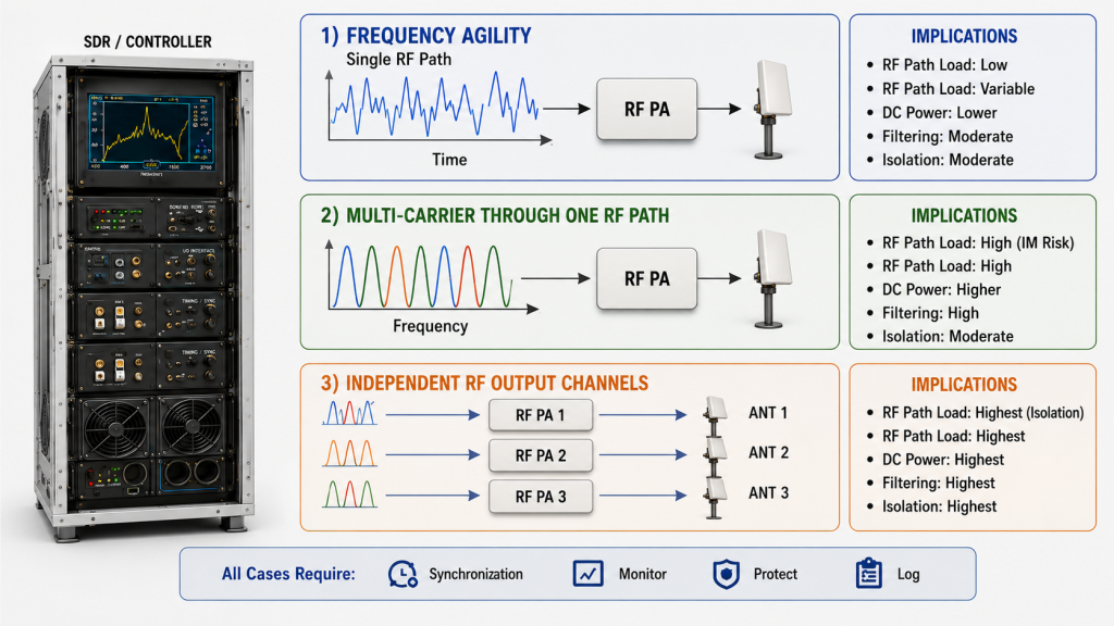
Distinguish three different simultaneous-operation cases
A wide frequency range does not prove that one RF channel can satisfy every simultaneous signal requirement.
The RFQ must distinguish between:
- Frequency agility
One RF path changes from one frequency to another at different times. - Multi-carrier operation through one RF path
Several signals are combined and amplified through the same PA and output path. - Independent RF output channels
Several separate RF paths operate at the same time.
These cases create different requirements for:
- total output power;
- linearity;
- peak-to-average power ratio;
- intermodulation;
- filtering;
- channel isolation;
- DC load;
- thermal load;
- antenna routing;
- acceptance testing.
A wideband PA may be suitable for frequency agility but not for several independent output channels. It may also support multi-carrier operation only if total power, linearity, thermal behavior, and filtering remain within the approved limits.
| Project Condition | Wideband Starting Point | Narrowband Starting Point | Mixed Starting Point |
|---|---|---|---|
| One or two fixed critical bands | Possible, but may provide unused coverage | Strong candidate | Strong candidate when secondary bands also exist |
| Several separated required bands | Strong candidate if RF paths can be consolidated | Higher module and RF-path count | Strong candidate when some bands need dedicated margin |
| Likely future frequency changes | Preserves broader flexibility | Higher redesign risk | Preserves flexibility without broadening every channel |
| Strict output requirement at band edges | Requires strong edge-frequency evidence | Allows more frequency-specific optimization | Strong candidate for selected critical bands |
| Limited cabinet space | Favorable only if filtering and antenna paths can also be consolidated | Module count may increase space pressure | Useful only when dedicated critical paths justify added hardware |
| Limited cooling capacity | Verify worst-case dissipation across the assigned band and operating mode | May improve band-specific efficiency, but total module count still matters | Calculate the worst simultaneous thermal load |
| Several simultaneous channels | Clarify whether signals share one RF path or require independent channels | Dedicated paths simplify channel-level limits but increase hardware count | Strong candidate when priority channels need independence |
| Different bands require different output levels | Requires clear per-frequency limits and control | Easy to define by dedicated path | Strong candidate |
| Simplified maintenance is important | Fewer module types may help if the platform is genuinely common | More frequency-specific spares may be required | Requires a controlled spare and configuration strategy |
| Frequency plan remains uncertain | Strong candidate | Limited flexibility | Strong candidate |
The matrix identifies a starting point, not an automatic approval. Each option still requires comparable evidence under the same frequency, RF path, DC, thermal, and load conditions.
4. When a Mixed RF PA Architecture Reduces Project Risk
A mixed architecture is not a compromise made after wideband and narrowband options fail.
It is often the most deliberate design when fixed critical bands and flexible secondary coverage have different engineering priorities.

Dedicated paths for fixed critical bands
A narrowband path may be justified when a frequency group requires:
- strict minimum output;
- long hot-state operation;
- more controlled edge-frequency behavior;
- a dedicated antenna or filter path;
- independent protection and alarm limits;
- separate unit-level acceptance evidence.
These paths protect the channels that carry the highest operational and approval risk.
Shared coverage for secondary or changing bands
A wideband path may be suitable for:
- secondary frequency groups;
- future expansion;
- configurations that change between projects;
- non-simultaneous frequency requirements;
- bands that do not justify several dedicated modules.
This avoids building the entire cabinet around fixed-frequency hardware that may later become unnecessary.
Define each path by its own requirement
A mixed system does not require every path to have the same wattage, gain, or thermal limit.
Different bands may have different:
- feeder losses;
- antenna gains;
- coverage roles;
- duty cycles;
- output reference planes;
- acceptance limits.
The project should review multi-band RF power consistency by checking whether each channel meets its defined requirement. Identical readings across all bands are not automatically necessary.
Two common mixed structures are:
- Narrowband paths for fixed critical bands, with one wideband path for secondary or future coverage
- Independent narrowband paths for simultaneous priority channels, with shared wideband coverage for non-simultaneous requirements
Before approval, confirm:
- frequency ownership and overlap;
- simultaneous-operation combinations;
- RF path, filter, and antenna assignment;
- worst-case DC and thermal load;
- control and protection responsibility;
- acceptance limits for each path.
A mixed architecture reduces risk only when its channel boundaries are clearer than the alternatives.
5. What Evidence Must Support the Architecture Decision
The architecture decision should be based on measurements that can change the choice between wideband, narrowband, and mixed structures.
It does not require a complete production acceptance report at the first comparison stage. It does require enough evidence to prevent an unfair or incomplete comparison.

Use the same measurement boundary
Every output result must identify the reference plane.
Typical reference points include:
- PA output connector;
- cabinet RF output;
- feeder end;
- RF power delivered to the antenna input.
A requirement of 100 W at the PA output connector is not the same as 100 W delivered to the antenna input.
Filters, connectors, bulkheads, feeder cable, and mismatch can consume part of the available RF margin. The required reference plane may therefore change the architecture choice.
Test the frequencies that affect the decision
The comparison should include:
- lower assigned frequency;
- center frequency;
- upper assigned frequency;
- every project-critical frequency;
- overlap or handoff regions;
- frequencies with difficult antenna matching.
A wideband option should not be approved from one favorable center-frequency screenshot. Verified wideband RF performance should show whether output and thermal behavior remain acceptable across the frequencies assigned to that path.
Where the decision depends on lower- or upper-edge margin, require RF PA band-edge performance verification.
Include the operating condition that creates the highest risk
The evidence should reflect:
- required duty cycle;
- defined hot-state duration;
- actual module-input voltage;
- DC current under RF load;
- cooling configuration;
- forward and reflected power;
- VSWR or load boundary;
- simultaneous operating combination, where applicable.
For a 28 V DC system, the test should record the voltage at the module input while RF power is being delivered. A nominal power-supply setting does not prove that the same voltage reaches the PA under load.
Final production evidence should remain traceable to the delivered module. However, the architecture review should first focus on the measurements that can change the wideband, narrowband, or mixed decision.
| Evidence Item | What It Must Show | Why It Can Change the Architecture Choice |
|---|---|---|
| Required frequency points | Low, center, high, and project-critical results | Shows whether nominal coverage is usable |
| RF reference plane | Where the output requirement is measured | Prevents comparison of incompatible power values |
| Output and gain trend | Variation across the assigned frequencies | Shows whether wideband behavior is acceptable |
| Hot-state result | Output, current, and temperature after defined operating time | Reveals thermal margin |
| DC condition | Module-input voltage and current under RF load | Confirms supply and distribution margin |
| Load behavior | Forward power, reflected power, VSWR, and protection response | Shows sensitivity to the installed RF path |
| Simultaneous-operation result | Combined DC, thermal, and RF behavior | Confirms whether the proposed channel combination is practical |
| Comparison method | Same boundaries and conditions for each architecture | Supports a fair engineering decision |
RFQ Checklist: What to Define Before Final Approval
The RFQ should define:
- fixed, optional, and future frequencies;
- priority bands and simultaneous-operation combinations;
- required RF power and reference plane for each band;
- frequency-agile, multi-carrier, or independent-channel operation;
- duty cycle and hot-state duration;
- feeder, filter, connector, and antenna-path assumptions;
- expected VSWR or reflected-power boundary;
- available 28 V DC voltage and current;
- cooling method and ambient condition;
- control, protection, and required acceptance evidence.
The RFQ should not request only “wideband 100 W” or “narrowband 100 W.”
Those descriptions do not define:
- the required frequencies;
- where the power is measured;
- whether signals operate together;
- the thermal condition;
- the installed RF load;
- the evidence required for approval.
A complete supplier response should explain:
- Which architecture is recommended
- Which frequencies are assigned to each RF path
- Which channels may operate simultaneously
- What must be verified after cabinet integration
- What acceptance evidence will be delivered
Conclusion
Wideband, narrowband, and mixed RF PA architectures solve different integration problems.
Wideband architecture can preserve flexibility and reduce hardware fragmentation when several frequencies can genuinely share one platform, RF path, filtering strategy, and antenna plan.
Narrowband architecture can provide more room for frequency-specific optimization when fixed critical bands justify the additional hardware and integration effort.
Mixed architecture can protect priority channels while preserving broader coverage for secondary or future requirements.
The correct choice depends on:
- target frequencies;
- simultaneous-operation requirements;
- RF power and reference plane;
- installed RF path;
- antenna and VSWR conditions;
- duty cycle;
- cooling capacity;
- 28 V DC limits;
- control requirements;
- comparable engineering evidence.
Send the target frequencies, simultaneous-operation combinations, required RF power and reference plane for each band, duty cycle, and installed antenna-path assumptions. Also include the available 28 V DC capacity, cooling condition, control interface, VSWR boundary, and required S/N-linked acceptance evidence.
RF SKYPOWER can review whether a wideband, narrowband, or mixed RF PA architecture provides the clearer engineering path before the RFQ is locked.
The result should be a defined RF architecture with measurable acceptance boundaries—not a collection of modules selected only by bandwidth and wattage labels.