


Drone control links should be mapped to RF PA frequency coverage by converting an authorized airport C-UAS link inventory into target frequency points, PA band groups, antenna paths, output reference points, and test evidence before module selection begins. A list such as 900MHz, 1.2GHz, 1.5GHz, 2.4GHz, and 5.8GHz is only the starting point. Engineers still need to decide which link type each point represents, which RF Power Amplifier Frequency Range can cover it, and whether the installed system can verify usable output at that point.
The central conflict is simple: a frequency list tells you what to review, but a coverage map tells you how the RF chain must be designed and proven. In an airport perimeter C-UAS project, this difference matters because RF behavior must remain controlled, site-specific, and verifiable. A module datasheet may show a wide range, but the airport system still depends on antenna sector layout, feeder loss, VSWR behavior, thermal load, 28V supply margin, control logic, and acceptance evidence.
This article explains how engineers can move from drone link mapping to RF PA coverage planning without turning the process into an unsafe operating guide. The focus is engineering selection: how to group frequency points, choose module bands, check antenna paths, avoid blind spots, and prepare a better RFQ before final airport C-UAS integration.
1. Why Should Drone Link Mapping Come Before RF PA Selection?
Drone link mapping should come before RF PA selection because RF Power Amplifier Frequency Range is only meaningful after engineers know which control, telemetry, video, data, or navigation-related frequency points the airport C-UAS system is authorized and required to review. If the project begins with only “900MHz, 1.2GHz, 1.5GHz, 2.4GHz, and 5.8GHz coverage,” the supplier may choose modules that appear to cover the list but still leave unclear output targets, antenna paths, acceptance points, and site boundaries.
Here’s the engineering point: frequency coverage is not only a module shopping filter. It is a system planning step that connects the link inventory, airport perimeter layout, PA module band, antenna sector, control logic, and test report into one decision.

What Goes Wrong If You Start with the Module?
The main risk is that the project moves from a frequency list directly to a product model. A wideband PA may look attractive because it covers several listed points, but the system may still fail to prove usable output at the antenna path or under hot-state operation.
Before comparing RF Power Amplifier modules, engineers should define:
- Link type for each frequency point
- Airport area or antenna sector involved
- PA-port or antenna-port output reference
- Required duty condition
- Feeder and antenna path
- VSWR or protection expectation
- Test evidence required for acceptance
What Should Come First?
The first document should be a link-to-frequency map. It does not need to expose sensitive operating actions; it only needs to define which authorized link categories the airport project needs to account for in coverage planning.
Key Takeaway: Drone link mapping prevents the team from buying a frequency range before defining the coverage problem.
| Weak Starting Point | Better Starting Point | Why It Matters |
|---|---|---|
| Frequency list only | Link-to-frequency map | Shows why each point matters |
| Datasheet range only | PA band plus antenna path | Avoids module-only thinking |
| One output target | Output reference per frequency | Prevents unclear acceptance |
| One wideband assumption | Verified coverage matrix | Reduces hidden gaps |
This table helps engineers turn a purchasing request into a system design review.
2. What Drone Links Shape RF PA Frequency Coverage?
Airport C-UAS engineers should map drone link types before assigning RF Power Amplifier Frequency Range because different link functions can create different coverage, antenna, duty, and verification requirements. The goal is not to describe how to interfere with any specific platform. The goal is to organize the project’s authorized frequency requirements into a controlled RF planning matrix.
The practical risk is clear: two frequency points may look similar in a spreadsheet, but they may represent very different system roles. A control link, a telemetry path, a video or data path, and a navigation-related review point should not be treated as identical engineering items.

Which Link Categories Belong in the Map?
A useful airport C-UAS map usually starts with link function, not frequency. This keeps the planning process tied to system requirements rather than random frequency collection.
Common planning categories include:
- Control links
- Telemetry or status links
- Video or data links
- Link-management or backup behavior
- Navigation-related or timing-sensitive review points
- Future expansion or regional requirement points
For a broader Low-Altitude Security & C-UAS EW system, this link-first approach helps integrators keep module selection, antenna planning, and verification evidence aligned.
Why Should 1.5GHz Be Treated Carefully?
Navigation-related or timing-sensitive bands require special attention in airport environments. A frequency point near this area should not be treated as a routine output target without project authorization, site coordination, and compliance review.
Key Takeaway: Link categories keep the coverage map disciplined, especially in airport projects where RF behavior must be controlled and justified.
| Link Type | Coverage Planning Meaning | Engineering Check |
|---|---|---|
| Control | Command connection risk | Authorized target band |
| Telemetry | Feedback or status path | Link family mapping |
| Video/data | Often higher-band review | Antenna and feeder path |
| Navigation-related | Sensitive airport context | Compliance boundary |
| Future expansion | Architecture reserve | Upgrade path |
This table keeps the frequency discussion inside engineering planning rather than unsafe operating detail.
3. How to Map 900MHz to 1.5GHz RF PA Coverage
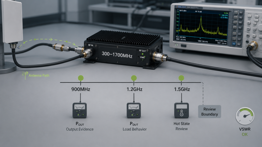
900MHz to 1.5GHz fits RF PA coverage as a low-to-mid band planning group, but RF Power Amplifier Frequency Range approval still needs separate evidence at 900MHz, 1.2GHz, and 1.5GHz. These points may sit inside the same module family, yet they can differ in antenna behavior, feeder loss, output curve, thermal load, and site approval requirements.
This is where system integrators should pay attention: one module range can include several points, but inclusion is not proof of equal usable behavior. A 900MHz result does not automatically prove 1.2GHz behavior, and a 1.2GHz result should not be used as the only evidence for 1.5GHz in an airport RF chain.
How Should Engineers Review the Low-to-Mid Group?
Engineers should review the group as a set of separate target points inside one possible PA band. This is different from assuming the whole range is equally strong.
A practical check should include:
- 900MHz output and load behavior
- 1.2GHz output and hot-state behavior
- 1.5GHz project authorization and site boundary
- Antenna support for each point
- Feeder loss at each point
- VSWR and reflected-power status
- Test report evidence per point
A 300–1700MHz RF Power Amplifier module may be reviewed for 900MHz, 1.2GHz, and 1.5GHz coverage, but each frequency still needs its own evidence.
When Would 300–2700MHz Matter?
A 300–2700MHz path may be considered when the architecture wants low-to-mid coverage and 2.4GHz inside a broader module plan. This can reduce band grouping complexity, but it also requires careful output flatness, heat, and antenna-path review.
Key Takeaway: Low-to-mid band grouping is useful for planning, but each listed frequency remains a separate acceptance point.
| Frequency Point | Planning Role | Do Not Assume |
|---|---|---|
| 900MHz | Low-to-mid coverage point | Same behavior as 1.2GHz |
| 1.2GHz | Mid-band evidence point | Covered by 900MHz data |
| 1.5GHz | Sensitive review point | Routine approval without coordination |
| 300–1700MHz band | Possible grouped module | Equal output at all points |
| 300–2700MHz band | Broader architecture option | No thermal or antenna trade-off |
This table helps engineers use grouped bands without hiding point-specific verification needs.
4. How to Map 2.4GHz and 5.8GHz RF PA Coverage
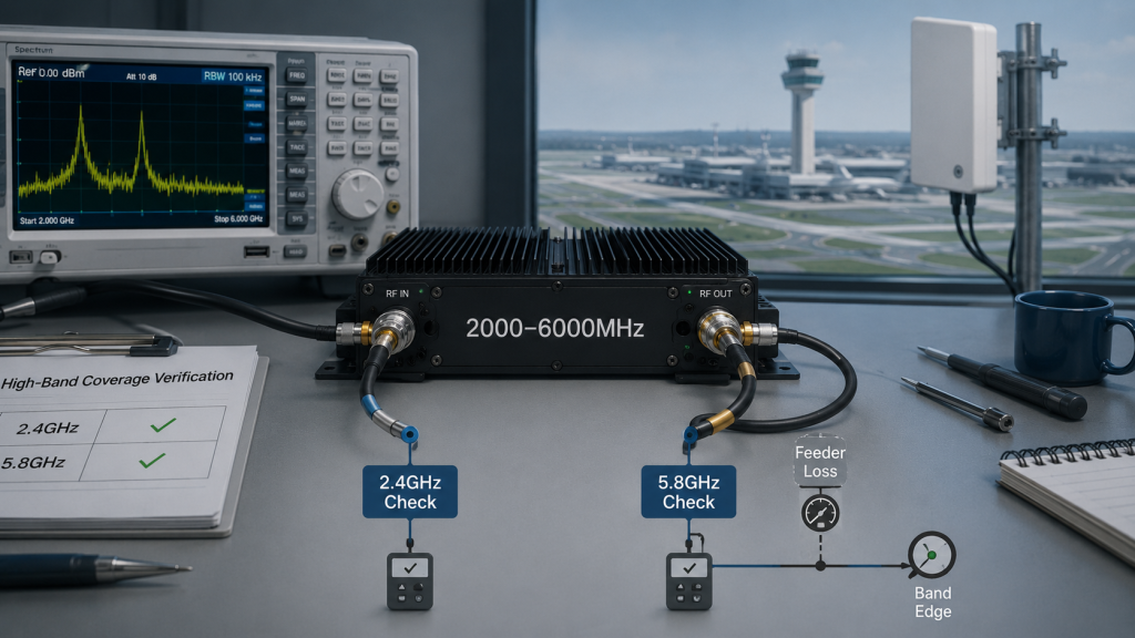
2.4GHz and 5.8GHz should map to high-band PA coverage separately because RF Power Amplifier Frequency Range may include both points while path loss, antenna behavior, output margin, and thermal load differ sharply between them. A 2000–6000MHz module can be a strong candidate for this group, but the system still needs separate evidence at 2.4GHz and 5.8GHz.
Here’s the field reality: high-band coverage is often where weak assumptions appear first. Cable routing, connector quality, antenna directionality, and band-edge output can matter more at higher frequencies than a simple product range suggests.
What Should Be Checked at 2.4GHz?
2.4GHz should be checked as its own target point in the PA coverage matrix. It may share a high-band PA path, but the system still needs to define where output is measured and how antenna coverage is assigned.
Useful checks include:
- PA module band assignment
- Antenna sector assignment
- PA-port or antenna-port reference
- Feeder and connector path
- Duty condition
- Hot-state output
- VSWR or reflected-power status
Why Is 5.8GHz More Sensitive?
5.8GHz may expose edge-frequency behavior, feeder loss, connector sensitivity, and antenna-direction issues more clearly. A clean lower high-band result should not be used as proof that the upper point is also ready.
A 2000–6000MHz RF Power Amplifier module should be checked at both 2.4GHz and 5.8GHz because high-band coverage cannot be proven by one favorable center-frequency result.
Key Takeaway: High-band PA coverage must be proven by target-point evidence, not only by the fact that 2.4GHz and 5.8GHz sit inside one datasheet range.
| High-Band Point | Main Planning Risk | Better Check |
|---|---|---|
| 2.4GHz | Treated as generic high band | Define output reference |
| 5.8GHz | Assumed from lower-band result | Check target-point evidence |
| Shared PA path | Hidden performance variation | Compare both points |
| Long feeder path | Higher installed loss | Verify antenna-end result |
| Wideband module | Range mistaken for proof | Require test data |
This table keeps high-band planning tied to measured behavior instead of range labels.
5. What Makes an RF PA Frequency Coverage Matrix Useful?
A coverage matrix is better than a frequency list because RF Power Amplifier Frequency Range decisions need link type, target frequency, PA band, antenna path, output reference, duty condition, protection behavior, and acceptance evidence—not only a list of numbers. A frequency list helps begin the discussion, but it cannot complete module selection or airport perimeter approval.
The better check is simple: every frequency should have a reason, a path, a reference point, and evidence. If one of those fields is missing, the coverage plan is not ready for final PA approval.

What Should the Matrix Include?
The matrix should be practical enough for RFQ and engineering review. It should not become an unsafe operating table or an overcomplicated research model.
Useful fields include:
- Link type
- Target frequency
- Priority level
- PA module band
- Antenna sector or path
- Output reference point
- Required usable output
- Duty-cycle assumption
- VSWR or protection requirement
- Test evidence
- Compliance note
A 300–2700MHz RF Power Amplifier module can be considered when one architecture needs to include low-to-mid points and 2.4GHz, but the matrix should still show which points are actually verified.
What Gaps Does the Matrix Reveal?
A matrix can reveal that a point is inside the nominal PA range but lacks hot-state data, antenna compatibility, or system-level reference. It can also show where one frequency needs compliance review before it becomes a final system target.
Key Takeaway: A matrix turns frequency coverage from a product claim into a reviewable engineering plan.
| Matrix Field | Question It Answers | Risk If Missing |
|---|---|---|
| Link type | Why is this point needed? | Unclear priority |
| PA band | Which module path covers it? | Wrong architecture |
| Antenna path | Where does RF energy go? | Hidden blind spot |
| Output reference | Where is output judged? | Test dispute |
| Evidence | How is coverage proven? | Weak acceptance |
This table helps teams see why a frequency list is only the first step, not the final selection document.
6. How Many RF PA Bands Does Airport Coverage Need?
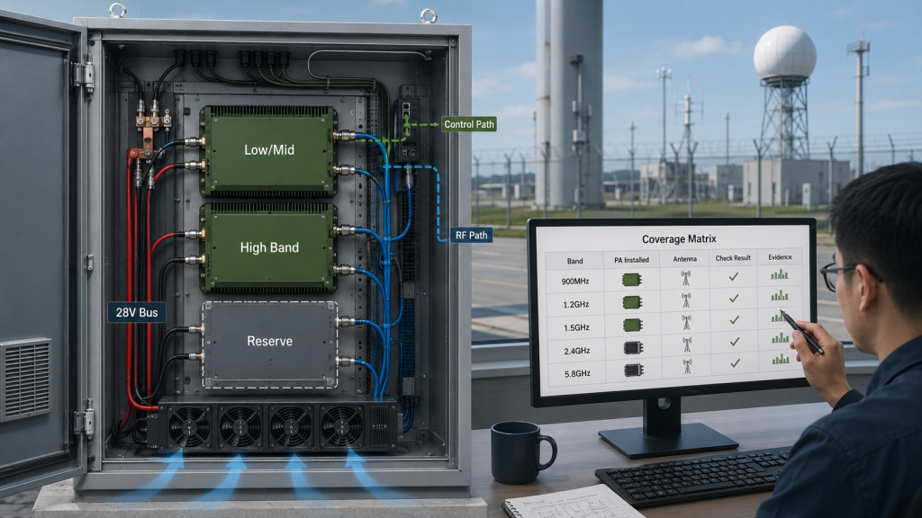
Airport coverage needs as many RF PA bands as required to verify each authorized frequency point, but RF Power Amplifier Frequency Range grouping should also avoid unnecessary hardware, heat, DC load, and control complexity. There is no responsible universal answer such as “one wideband module is always enough” or “more bands are always safer.” The correct band count depends on the coverage matrix.
This is the selection risk: too few PA bands can hide weak points, while too many PA bands can create a cabinet that is expensive, hot, difficult to control, and harder to maintain. The right architecture comes from comparing frequency grouping, antenna sectors, output targets, duty cycle, and test evidence.
What Architecture Options Should Be Compared?
Engineers can compare several broad approaches. Each can be valid when the evidence supports it.
Common options include:
- A wideband single-path concept
- A grouped low/mid plus high-band architecture
- A sector-based or mission-based architecture
- A hybrid plan with reserved upgrade paths
- Separate high-band treatment for 2.4GHz and 5.8GHz
An airport perimeter case can show why RF coverage must be planned around tower communications, controlled deployment, antenna sectors, and verified RF behavior before final approval.
What Decides the Best Band Grouping?
The best band grouping depends on whether the system can prove usable behavior at every required point. If 900MHz, 1.2GHz, and 1.5GHz can be handled in one low-to-mid group, that may simplify the system. If 2.4GHz and 5.8GHz behave differently under heat or feeder loss, they may need more careful high-band review.
Key Takeaway: PA band count should be chosen from coverage evidence, not from the desire to minimize or maximize the number of modules.
| Architecture Option | Advantage | Trade-Off |
|---|---|---|
| Wideband single path | Fewer modules | Harder full-range proof |
| Low/mid plus high group | Clearer band control | More hardware paths |
| Sector-based design | Better site alignment | More planning effort |
| Hybrid upgrade plan | Future reserve | Requires space and control |
| Over-stacked bands | Looks complete | More heat and complexity |
This table helps engineers compare architecture choices without assuming that either the widest or most complex option is best.
7. How Do Antennas Change the Link-to-PA Coverage Map?
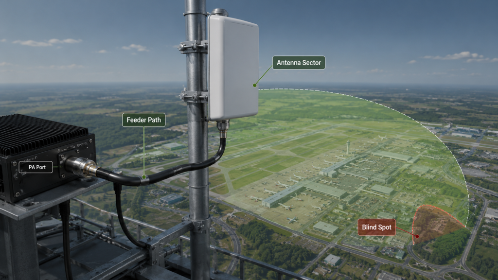
Antennas change the link-to-PA coverage map because RF Power Amplifier Frequency Range only becomes useful when the antenna band, feeder path, direction pattern, polarization, installation position, and VSWR behavior support the same airport coverage requirement. A PA can cover a frequency point at the output port while the installed antenna path fails to deliver usable coverage.
Here’s the engineering point: PA coverage and system coverage are not the same. Airport perimeter designs must connect every frequency point to a real antenna sector and a real verification boundary.
What Antenna Fields Belong in the Map?
The map should include more than the antenna model name. It should show whether the antenna path can actually support the frequency point and airport sector.
Useful antenna fields include:
- Antenna band
- Gain and direction pattern
- Sector or perimeter zone
- Polarization assumption
- Installation height and position
- Feeder length and connector count
- VSWR behavior
- PA-port or antenna-port output reference
For airport Counter-UAS RF planning, Airport Counter-UAS RF Solutions should be reviewed around controlled energy, site boundaries, and operational safety rather than treating every frequency point as the same output problem.
How Can Antennas Create Blind Spots?
Blind spots can appear when the PA supports a frequency but the antenna does not, when the antenna direction misses a perimeter area, or when feeder loss reduces high-band antenna-end output. A strong module result cannot fix an unverified antenna sector.
Key Takeaway: Antenna data must sit inside the coverage map, not outside it as a later installation detail.
| PA Condition | Antenna Condition | Resulting Risk |
|---|---|---|
| PA covers frequency | Antenna does not | No real system coverage |
| PA output is strong | Sector is misaligned | Coverage gap |
| PA passes dummy load | VSWR rises on antenna | Protection or output drop |
| High-band PA selected | Long feeder path | Antenna-end weakness |
| Shared antenna path | Poor isolation | Harder diagnostics |
This table reminds engineers that RF PA coverage is only useful when the antenna path supports the same requirement.
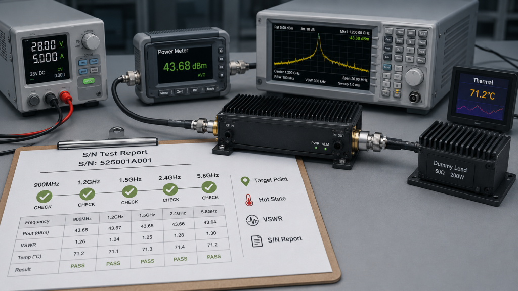
8. How to Prove RF PA Frequency Coverage in Tests
900MHz to 5.8GHz coverage should be proven with target-point data because RF Power Amplifier Frequency Range labels do not prove usable output, thermal behavior, VSWR stability, or antenna-path performance at every listed frequency. If the project claims coverage at 900MHz, 1.2GHz, 1.5GHz, 2.4GHz, and 5.8GHz, those points should be treated as separate evidence points.
The better check is simple: do not let one center-frequency result represent a whole airport coverage plan. Each project-critical point should have its own measurement boundary, thermal condition, protection state, and acceptance logic.
What Evidence Should Be Requested?
Evidence should be tied to the coverage matrix. It should show not only that the PA turns on, but that the required frequency point remains usable under defined conditions.
Request evidence for:
- Target frequency point
- PA-port output
- Antenna-port or system reference when required
- Input drive level
- 28V supply voltage and current
- Module temperature or hot-state condition
- Duty-cycle assumption
- Load condition
- VSWR or reflected-power status
- Over-temperature, over-voltage, or alarm state
- Module serial number
- Test date and setup notes
Wideband RF Power Amplifier verification should include target frequency points, thermal behavior, VSWR status, and report evidence before engineers approve airport C-UAS coverage.
How Can Source-Factory Evidence Strengthen Approval?
Source-factory evidence matters because frequency coverage is easier to approve when module data, protection behavior, and report traceability are connected. RF SKYPOWER can support S/N-linked test reports, target-point output checks, VSWR / temperature / voltage protection review, 28V supply behavior, and wideband coverage evidence, so integrators can compare the coverage matrix with real module verification rather than relying only on a datasheet range.
Key Takeaway: A valid coverage claim needs target-point evidence, not a broad range label or a single clean test result.
| Evidence Type | What It Proves | Weak Alternative |
|---|---|---|
| Target-point output | Actual frequency behavior | Nearby frequency result |
| Hot-state data | Sustained behavior | Cold short test |
| VSWR status | Antenna/load stability | Output only |
| S/N-linked report | Unit traceability | Generic datasheet |
| Reference point | Fair comparison | Unclear meter location |
This table helps procurement teams request proof that matches the coverage claim.
9. How Can Airport Teams Avoid Over-Coverage and Blind Spots?
Airport teams can avoid over-coverage and blind spots by using RF Power Amplifier Frequency Range as one part of a controlled site-specific RF plan, not as permission to apply every frequency point with the same power, antenna, and operating boundary. Airport projects require a balance between link coverage, verified RF behavior, operational safety, and compliance boundaries.
Here’s the field reality: the best system is not the one that blindly covers the most spectrum. The better system puts the right verified RF capability into the right band, right sector, right duty condition, and right approval boundary.
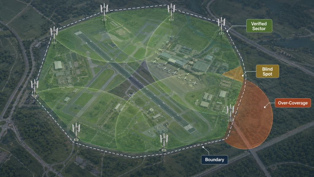
What Creates Blind Spots?
Blind spots can come from missing frequencies, weak antenna sectors, high-band feeder loss, unverified thermal behavior, or a mismatch between PA coverage and antenna coverage. They may also appear when one airport perimeter zone uses a different feeder length or antenna height than another.
Typical causes include:
- Frequency point missing from the matrix
- PA band selected but antenna band missing
- 5.8GHz path approved from lower-frequency data
- Long feeder path in one sector
- No hot-state output check
- No site-specific reference point
What Creates Over-Coverage?
Over-coverage can come from treating wide frequency range as a goal by itself. In an airport setting, this may create more RF management complexity than the project needs.
Multi-band C-UAS systems should also check RF power consistency after each drone link frequency is assigned to a PA band and antenna path.
Key Takeaway: Airport C-UAS frequency coverage should be controlled, verified, and site-specific, not simply as wide or as strong as possible.
| Planning Problem | Likely Cause | Better Control |
|---|---|---|
| Blind frequency gap | Link not mapped | Link inventory review |
| Weak sector | Antenna mismatch | Sector-path verification |
| High-band drop | Feeder or connector loss | Antenna-end check |
| Overbuilt cabinet | Too many bands | Priority-based grouping |
| Compliance uncertainty | Unclear boundary | Site approval review |
This table helps airport teams reduce both under-design and uncontrolled over-design.
10. What RFQ Data Defines RF PA Frequency Coverage?
Engineers should tell the RF PA factory the link-to-frequency map, target output point, antenna path, duty cycle, site condition, protection requirements, and test-report expectations before final RF Power Amplifier Frequency Range selection. A request that only says “cover 900MHz, 1.2GHz, 1.5GHz, 2.4GHz, and 5.8GHz” is not enough for a reliable airport perimeter design.
This is the final decision point: the factory cannot judge real coverage from a frequency list alone. It needs the system boundary that turns the frequency list into a verifiable PA coverage plan.

What Should Be Included in the RFQ?
A better RFQ gives the source factory enough information to judge module grouping, test needs, and integration risk. It does not replace airport compliance review, but it improves technical selection.
Send these items before final selection:
- Airport perimeter or other site scenario
- Target frequency points
- Link type for each frequency
- Priority level
- Output reference point
- PA-port or antenna-port requirement
- Antenna distance and feeder path
- Fixed-site cabinet condition
- Duty cycle or operating profile
- Single-band or multi-band operation
- 28V supply condition
- Cooling method
- VSWR, over-temperature, and over-voltage protection needs
- Control interface expectations
- Required test report format
- S/N-linked data requirement
How Can Source-Factory Review Help?
As a source factory for RF Power Amplifier modules and C-UAS core components, RF SKYPOWER can help engineers review drone link frequency points, PA band grouping, antenna path, output reference point, duty cycle, protection behavior, and repeatable test evidence before final module approval. RF SKYPOWER supports wideband RF modules, CNC housings, copper heat spreading, VSWR / temperature / voltage protection, and S/N-linked test reports, so airport C-UAS integrators can compare frequency coverage plans with real module and system verification data.
Key Takeaway: The best factory discussion is not “which module covers the list?” but “which verified PA coverage plan fits the airport system boundary?”
| RFQ Item | Why the Factory Needs It | Risk If Missing |
|---|---|---|
| Link-to-frequency map | Defines coverage purpose | Wrong band grouping |
| Output reference point | Defines acceptance | Test disputes |
| Antenna path | Connects PA to site | Hidden weak zones |
| Duty cycle | Defines heat load | Unstable operation |
| Protection needs | Defines control logic | Blind alarms |
| Report format | Defines proof | Weak delivery evidence |
This table gives engineers a practical checklist before asking for final PA module selection.
FAQ
Can I choose RF PA coverage from 900MHz to 5.8GHz directly?
No. A frequency list is only the starting point. You should map each frequency to link type, PA band, antenna path, output reference point, duty condition, protection behavior, and test evidence before choosing modules.
What is the best RF PA band for 900MHz, 1.2GHz, and 1.5GHz?
The best band depends on output target, antenna path, feeder loss, thermal behavior, and compliance boundary. A 300–1700MHz or broader module may fit on paper, but each point still needs separate verification.
Should 2.4GHz and 5.8GHz use the same RF PA module?
They can use the same high-band PA when the module, antenna path, thermal behavior, and acceptance data support both points. Do not approve 5.8GHz only from a 2.4GHz result.
How do I avoid blind spots in airport C-UAS RF coverage?
Start with a link map, then build a PA coverage matrix and an antenna sector map. Check target-point output, antenna support, feeder path, VSWR status, duty condition, and site-specific acceptance evidence.
What should I send to the RF PA factory before quotation?
Send target frequency points, link type, priority, output reference point, antenna path, feeder length, duty cycle, 28V supply condition, cooling method, protection requirements, control interface needs, and required test-report format.
Conclusion
Airport C-UAS engineers should not select RF Power Amplifier Frequency Range from a frequency list alone. They should first map drone control, telemetry, video, data, and navigation-related link categories to target frequency points, then assign each point to PA bands, antenna paths, output references, duty conditions, protection behavior, and repeatable test evidence. This is how a list such as 900MHz, 1.2GHz, 1.5GHz, 2.4GHz, and 5.8GHz becomes an engineering coverage plan instead of a loose procurement request.
The practical decision is clear: build the link map first, build the frequency coverage matrix second, then choose the PA module architecture. A datasheet range can shortlist a product family, but it cannot prove airport perimeter coverage by itself. The final decision should come from verified behavior across target points, antenna sectors, feeder paths, hot-state conditions, protection status, and S/N-linked reports.
As an RF Power Amplifier module and C-UAS core component source factory, RF SKYPOWER can support airport perimeter projects by reviewing drone link frequency points, PA band grouping, antenna path, output reference point, duty cycle, protection behavior, thermal margin, 28V supply behavior, and repeatable test evidence before final approval. This source-factory review helps turn a frequency list into verified PA coverage evidence, not just a module range recommendation. If your team needs to convert a frequency list into a verified RF PA coverage plan, you can discuss your project with RF SKYPOWER before the module architecture, antenna layout, and test boundary become expensive to change.
Controlled airport C-UAS performance starts with verified frequency coverage mapping, not a datasheet range alone.