


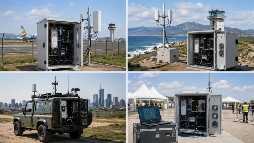
To choose Broadband RF Power Amplifier Modules, start by verifying installed RF behavior, not only the frequency range printed on a datasheet. In C-UAS and drone jammer systems, a module may cover the target band in theory, but the real system question is whether it can deliver stable usable output after drive level, cabinet routing, feeder loss, antenna VSWR, heat, voltage behavior, protection feedback, and delivery evidence are included.
The central conflict is clear: frequency coverage tells you where a module can operate, but system verification tells you whether the installed RF chain can rely on that output. For system integrators, RF engineers, and procurement reviewers, the decision is not simply “Which broadband PA covers this band?” The better question is “Which module can maintain usable full-band output in the actual C-UAS deployment?”
RF SKYPOWER helps integrators review broadband PA requirements before quotation, including target bands, output level, duty cycle, antenna path, cooling limits, control logic, and test evidence.
1. What Broadband RF PA Modules Do in C-UAS
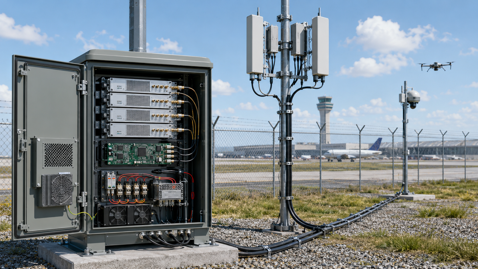
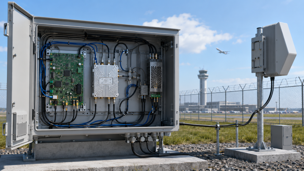
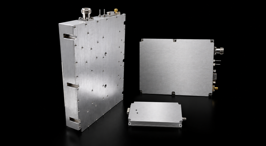
Broadband RF PA Modules act as the main RF power stage between the signal source and the antenna path in a C-UAS system. They take a controlled low-power RF signal from an SDR, exciter, or signal-generation chain and raise it to the level required by the installed transmit path.
How Does the Module Fit Into the RF Chain?
In the C-UAS RF chain, RF Power Amplifier modules are the stage that turns a controlled low-power RF signal into the power level the antenna path must handle. The module is not the whole jammer system, and it should not be approved as if it were isolated from the cabinet, feeder, antenna, and controller.
A typical C-UAS RF path includes:
- SDR or signal source
- RF input drive and control logic
- Broadband PA module
- Cabinet RF output
- Feeder cable and connector path
- Antenna feed and antenna load
- Alarm or status feedback to the controller
Here’s the engineering point: a PA module can pass a clean factory output test and still lose usable power after cabinet feedthroughs, cable routing, connector transitions, or antenna mismatch.
Why Is This Different From a Generic RF Amplifier?
In a general RF application, broadband performance may be described mainly by frequency range, gain, output power, and efficiency. In C-UAS integration, the same module also has to support multi-band architecture, high-duty operation, outdoor cabinet behavior, fast troubleshooting, and repeatable acceptance evidence.
Key Takeaway: A broadband PA should be approved as part of the installed RF chain, not only as a catalog component.
| Wrong Assumption | Better Engineering Check |
|---|---|
| The PA is a standalone part | Check the SDR-to-antenna chain |
| Frequency range proves system fit | Verify full-band output behavior |
| PA-port power is final power | Define the installed output boundary |
| Protection is only for shutdown | Use feedback for fault diagnosis |
This table helps buyers treat the module as a system power stage instead of a disconnected RF block.
2. How to Verify Broadband RF PA Modules
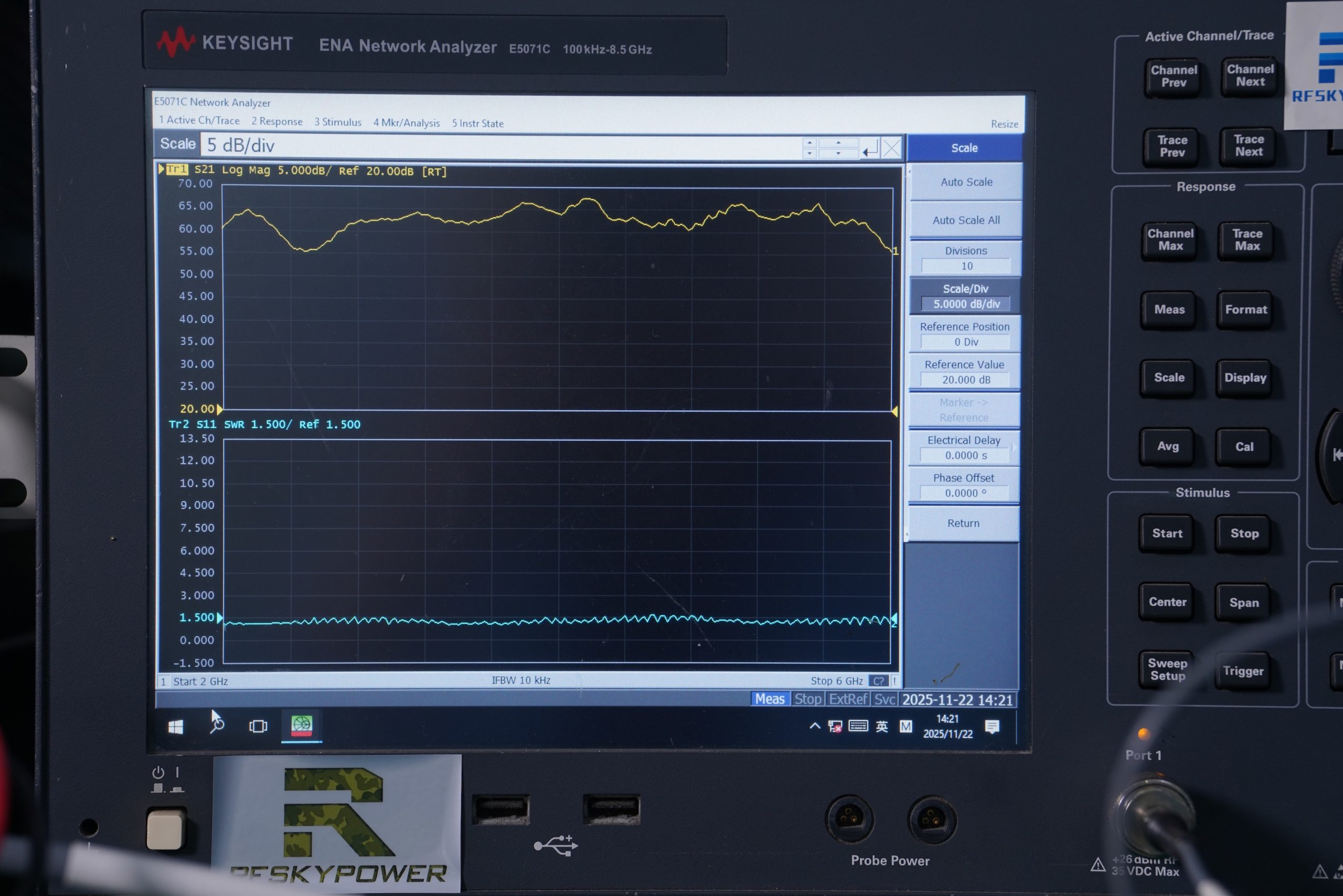
Broadband RF PA Modules can cover a wide operating range while still showing different output, gain, efficiency, heat, and reflected-power behavior across the band. Frequency range is only the first filter; it does not prove that every required point can deliver stable usable power.
What Does Frequency Range Actually Confirm?
A stated operating band only answers the first question: whether the module frequency range overlaps the target bands. After the target band is confirmed, gain flatness shows whether the same input drive produces predictable amplification across the operating range.
Before approving a broadband PA, check:
- Low-edge output
- Mid-band output
- High-edge output
- Project-critical frequency points
- Gain flatness
- Output flatness
- Current during sweep
- Temperature during sweep
- Load condition and measurement boundary
The selection risk appears here: a module may look correct because the range includes the target band, while one critical frequency still has lower output margin.
What Should Replace Datasheet-Only Review?
Datasheet review should be followed by full-band output evidence. The buyer should know how the module behaves at target points, not only whether those points fall inside the advertised range.
Key Takeaway: Frequency range tells you where to test; full-band evidence tells you whether the module is usable.
| Datasheet Claim | What It Does Not Prove | Better Evidence |
|---|---|---|
| 30–512MHz | Equal low-band output | Target-point sweep data |
| 300–2700MHz | Stable output across band | Output flatness report |
| 2000–6000MHz | Strong high-band behavior | 2.4GHz and 5.8GHz data |
| Wideband module | Continuous stability | Hot-state output check |
This table turns the buying question from “Does it cover the band?” into “What does it deliver across the band?”
3. What Broadband RF PA Module Ranges Fit C-UAS
Broadband RF PA Modules fit C-UAS projects when the frequency range and power level match the target bands, antenna strategy, cabinet space, duty cycle, and acceptance boundary. The widest module is not always the best module if the installed system cannot support the heat, power path, or antenna behavior that comes with it.
What Product Matrix Should Buyers Review?
The selection path should be visible before the buyer compares individual models. Frequency range, power class, and application role should be discussed together.
| Module Direction | Typical Frequency Range | Typical Power Options | C-UAS Fit |
|---|---|---|---|
| Low-band wideband | 30–512MHz | 30W–200W class | Low-frequency coverage planning |
| Sub-GHz / lower mid-band | 300–1200MHz | 30W–200W class | Lower-range multi-band systems |
| Mid-band wideband | 300–1700MHz | 30W–200W class | Flexible RF chain planning |
| Extended mid-band | 300–2700MHz | 30W–200W class | Multi-band C-UAS cabinets |
| High-band wideband | 2000–6000MHz | 30W–200W class | 2.4GHz / 5.8GHz review |
| Custom engineering | 20MHz–20GHz | Project-defined | Non-standard RFQ needs |
The practical risk is clear: a wider module can still delay acceptance if output, heat, and high-band behavior are not verified early.
When Does Custom Frequency Planning Make Sense?
Custom planning matters when the project has non-standard bands, special cabinet limits, unusual duty cycle, or strict acceptance testing. In that case, the RFQ should define target frequency, output per band, input drive, output boundary, cooling condition, antenna path, and required test evidence before pricing.
Key Takeaway: Product selection should move from frequency range to full system fit.
| Selection Need | Better Starting Point |
|---|---|
| Known fixed band | Narrowband or focused module |
| Multiple known bands | Broadband or mixed architecture |
| Uncertain future bands | Broadband with upgrade margin |
| Non-standard band plan | Custom RF engineering review |
| High-power high-band use | Full-band thermal and output proof |
This table helps engineering and procurement choose a module route before discussing only wattage and price.
4. Which C-UAS Deployments Need Which PA Approach?
Broadband RF PA Modules should be matched to the deployment scenario because airport, border, vehicle, rooftop, and temporary event systems create different RF path risks. The same PA class can behave differently when antenna distance, cabinet airflow, duty cycle, maintenance access, and DC supply conditions change.
How Do Deployment Scenarios Change Selection?
This becomes more important in low-altitude security and C-UAS EW deployments, where one cabinet may need to support multiple RF bands, outdoor cooling limits, and remote fault diagnosis. The deployment role decides which PA risks deserve the most attention.
| Deployment Scenario | Main RF Pressure | Selection Focus |
|---|---|---|
| Airport perimeter | Wide-area reliability | Full-band output and traceability |
| Border and coastline | Long antenna path | Feeder loss and antenna-port power |
| Vehicle-mounted system | DC and vibration pressure | Voltage stability and compact cooling |
| Rooftop city cabinet | Heat and access limits | Duty cycle and thermal margin |
| Temporary event security | Fast setup and retest | Clear measurement boundary |
| Critical infrastructure | Long service life | Locked BOM and S/N reports |
Here’s the field reality: a fixed rooftop cabinet and a vehicle-mounted cabinet may use similar modules, but they do not stress the RF chain in the same way.
Why Does Scenario-Based Review Reduce Risk?
Scenario-based review prevents the buyer and supplier from discussing the module in a vacuum. If the antenna is far from the cabinet, feeder loss becomes part of power selection. If the cabinet runs in high ambient temperature, continuous output and thermal margin become more important than short peak output.
Key Takeaway: The deployment scenario decides which PA risks matter most.
| Field Condition | Selection Risk |
|---|---|
| Long feeder route | Antenna-end output may drop |
| Closed outdoor cabinet | Heat may reduce usable power |
| Vehicle DC rail | Voltage drop may affect output |
| Multiple RF bands | Weak band may limit system value |
| Remote maintenance site | Traceability becomes critical |
This table helps buyers connect real installation conditions to the correct PA review path.
5. How to Check Broadband RF PA Module Output
Broadband RF PA Modules should be verified by rated output, measured output, and installed usable output across the required bands. Rated wattage is useful for product grouping, but it does not show how much power remains after cabinet interfaces, feeder cable, connector transitions, and antenna load are included
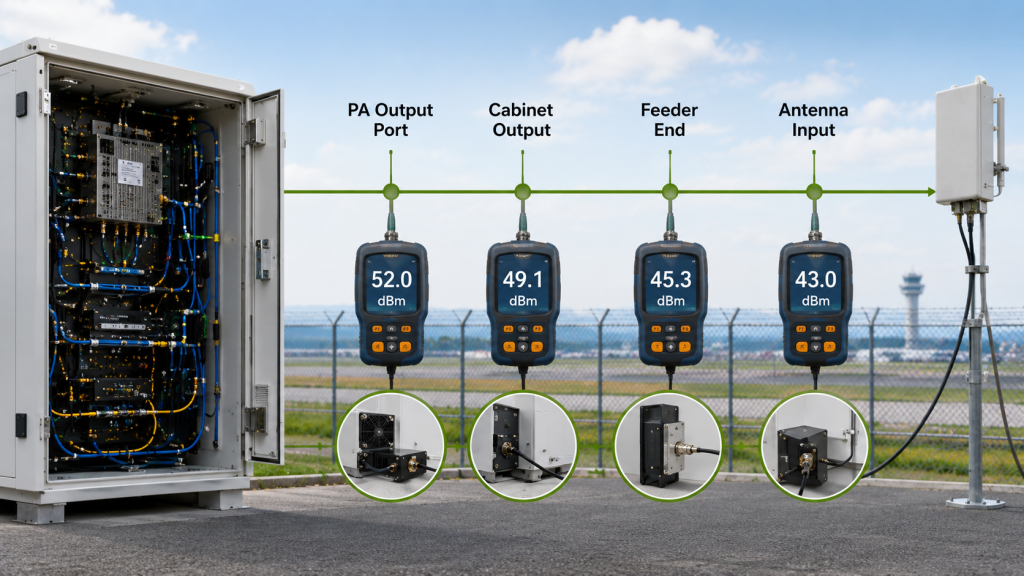
How Are Rated and Usable Output Different?
The output number should always be tied to a defined RF boundary, because RF output power at the PA connector is not the same as delivered power after the installed path. Rated output describes the module class; usable output describes what the system can rely on at the selected reference point.
Before approval, define:
- PA module output port
- Cabinet RF output
- Feeder-end output
- Antenna input
- Test cable and load condition
- Frequency points used for comparison
- Cold-state and hot-state conditions
The better check is simple: do not compare two wattage numbers unless they were measured at the same RF boundary.
Why Does Antenna-Port Power Matter?
Before choosing a 100W, 150W, or 200W class module, the team should account for how feeder cable and connector loss reduces the power that actually reaches the antenna. A higher PA rating may help, but it should not be used to hide an undefined RF path.
Key Takeaway: Output power is meaningful only when the measurement boundary is clear.
| Power Term | What It Means | Buyer Risk |
|---|---|---|
| Rated output | Module class | Can be overread |
| PA-port output | Module-side result | Ignores feeder path |
| Cabinet output | After internal routing | May miss antenna loss |
| Antenna-port output | Installed usable input | Best system reference |
This table helps prevent acceptance disputes caused by comparing different measurement points.
6. Why Does Continuous Output Matter More Than Bursts?
Broadband RF PA Modules need continuous or duty-cycle verification when the C-UAS system must operate beyond short RF bursts. A short burst may prove peak capability, but it does not prove thermal balance, current stability, voltage margin, or protection behavior over time.
What Does Burst Testing Miss?
Burst testing can hide problems that appear only after heat, load, and current build up. This matters in fixed sites, vehicle cabinets, rooftop systems, and border installations where the RF chain may run for longer periods.
Check these operating details:
- Burst, duty-limited, or continuous mode
- Single run duration
- Daily operating time
- Ambient temperature
- Cabinet airflow
- Heatsink design
- Module-end voltage
- Alarm behavior during heat rise
Here’s the engineering point: the problem is often not whether the module can reach peak power once, but whether it can hold usable output after heat has accumulated.
How Should Duty Cycle Be Shared Before RFQ?
A short burst result should not be treated as final approval unless the required RF Power Amplifier duty cycle has been tested under realistic heat, voltage, and cabinet conditions. Duty cycle should be part of the RFQ, not a late clarification after the module has already been quoted.
Key Takeaway: Continuous output approval should prove stable power under time, heat, and load.
| Test Type | What It Shows | What It May Hide |
|---|---|---|
| Short burst | Peak output reach | Heat drift |
| Low duty cycle | Basic recovery | Long-run stress |
| High duty cycle | Repeated load behavior | Cabinet heat buildup |
| Continuous run | Sustained capability | Needs full thermal proof |
This table helps buyers match the test method to the real operating pattern.
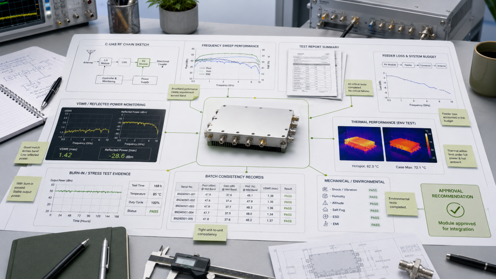
7. How Do Gain, VSWR, Voltage, and Heat Affect Selection?
Broadband RF PA Modules must be reviewed through gain flatness, output flatness, VSWR behavior, voltage stability, and thermal margin because these factors decide whether output remains predictable after integration. A strong module at one point can still become weak if the installed RF path, DC path, or cabinet condition is not controlled.
Why Are Gain and Output Flatness Both Needed?
Gain flatness tells you whether the module amplifies evenly across frequency. Output flatness tells you whether the delivered power stays usable across the target bands.
A useful sweep report should include:
- Frequency points
- Output power
- Gain
- Voltage
- Current
- Temperature
- FWD / REV / SWR
- Load condition
- Test boundary
This is where system integrators should pay attention: a smooth gain curve does not automatically mean strong antenna-port power after the cabinet and feeder path are added.
Why Do Protection Signals Matter?
If alarms appear after antenna installation, VSWR protection helps separate a real PA issue from antenna mismatch, reflected power, or feeder-path problems. If output falls only under full load, module-end voltage should also be checked before assuming the amplifier itself is weak.
Protection signals are useful because they turn a blind output drop into a diagnosable system event. Temperature status, voltage behavior, and reflected-power feedback can reduce unnecessary module replacement during field troubleshooting.
Key Takeaway: Flatness and protection feedback turn PA selection from a wattage comparison into an integration decision.
| Symptom | Possible Cause | Better Check |
|---|---|---|
| Weak high-band output | Gain or efficiency drop | Full-band sweep |
| Output falls under load | DC voltage drop | Module-end voltage |
| Repeated alarm | VSWR or heat | FWD / REV / temperature |
| Intermittent shutdown | Protection trigger | Status and recovery log |
This table helps field teams diagnose the system instead of blaming the module too early.
8. What Reports Should Broadband RF PA Modules Include
Broadband RF PA Modules should come with unit-level evidence that proves full-band behavior, operating condition, protection status, and repeatability. A single power screenshot is weak evidence because it cannot prove full-band output, continuous behavior, post-burn-in stability, or batch consistency.
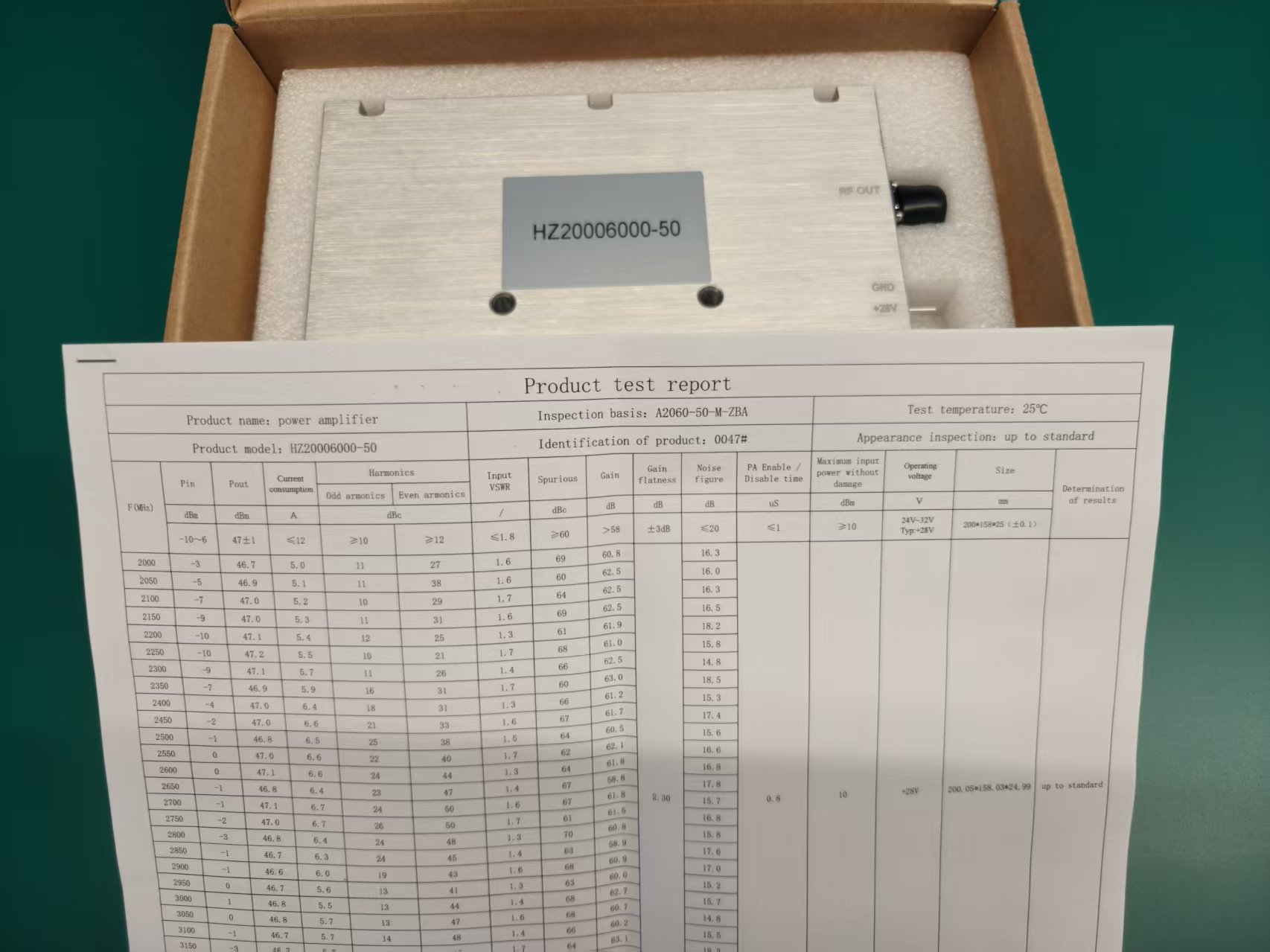
What Should a Useful Delivery Report Include?
A useful report should connect the test data to the actual unit. This is especially important when multiple PA modules are installed in one C-UAS cabinet or delivered across a batch.
Request evidence such as:
- Model and S/N
- Frequency points or sweep data
- Output power and gain
- Voltage and current
- Temperature condition
- FWD / REV / SWR
- Test load
- Measurement boundary
- Burn-in status
- Post-burn-in output recheck
- Pass/fail criteria
The practical risk is clear: without S/N-level evidence, factory approval, customer retest, maintenance replacement, and warranty review all become harder to align.
Why Do Burn-In and Batch Control Matter?
For fixed-site or high-duty C-UAS cabinets, batch burn-in is useful because it exposes thermal, electrical, or protection weaknesses before the modules leave the factory. Batch consistency also depends on supplier stability, including locked BOM control, repeatable test conditions, and S/N-level delivery records.
Key Takeaway: Delivery evidence is not paperwork; it is the bridge between factory approval and field retest.
| Weak Evidence | Better Evidence | Buyer Value |
|---|---|---|
| One power screenshot | Full-band report | Shows band behavior |
| Model-level claim | S/N-level report | Supports traceability |
| Cold test only | Post-burn-in recheck | Shows stressed condition |
| No boundary stated | Defined test point | Reduces disputes |
This table helps buyers separate simple sales proof from real acceptance evidence.
9. How to Quote Broadband RF PA Modules Faster
Broadband RF PA Modules can be selected faster when the RFQ includes frequency, output, duty cycle, antenna path, cabinet condition, electrical interface, control logic, and delivery evidence requirements. Without these details, the quotation may only match a catalog category instead of the real C-UAS deployment.
What RF Details Should Be Confirmed First?
A strong RFQ does not need to be complicated, but it should give enough information for engineering review. The goal is to prevent the supplier from quoting a module that fits the frequency range but misses the real acceptance condition.
Send these details:
- Target frequency range
- Critical bands
- Required output per band
- PA-port or antenna-port target
- Input drive level
- Burst, duty-limited, or continuous operation
- Ambient temperature
- Cabinet size and cooling method
- Feeder cable length and type
- Connector and adapter count
- Antenna type and distance
This is where early RFQ detail prevents rework. If the acceptance boundary is antenna-port output but the quotation is based on PA-port output, the project can look correct on paper and still fail retest later.
What Electrical and Control Details Matter?
Electrical and control information should include supply voltage, module-end voltage, current limit, enable logic, alarm feedback, AT command requirements, VSWR status, temperature status, and remote monitoring needs.
RF SKYPOWER can support early engineering review by checking whether the requested frequency range, output level, duty cycle, antenna path, cooling condition, alarm feedback, and test evidence match the intended C-UAS deployment.
Key Takeaway: A complete RFQ turns module selection from guesswork into an engineering review.
| RFQ Item | Why It Matters |
|---|---|
| Frequency and output per band | Prevents wrong module selection |
| Measurement boundary | Prevents acceptance disputes |
| Duty cycle | Separates burst from continuous needs |
| Antenna path | Predicts usable delivered power |
| Protection feedback | Supports field troubleshooting |
| Test evidence | Supports shipment and retest |
This table can be used directly by procurement and engineering teams before requesting a quote.
10. How Should Buyers Make the Final Broadband PA Decision?
Broadband RF PA Modules should be approved only when the selected module matches the target bands, power boundary, duty cycle, antenna path, thermal condition, protection feedback, and delivery evidence. The final decision should not be based on the widest frequency range or the highest rated wattage alone.

What Final Selection Logic Works Best?
The final selection path should move from application pressure to measurable evidence. This helps the buyer avoid choosing a module that looks attractive in the datasheet but creates integration problems later.
Use this decision order:
- Define the deployment scenario.
- Confirm target bands and critical bands.
- Define PA-port or antenna-port output target.
- Calculate feeder and connector loss.
- Confirm burst, duty-limited, or continuous operation.
- Check cabinet cooling and ambient temperature.
- Review VSWR, voltage, and temperature feedback.
- Request full-band and post-burn-in reports.
- Compare broadband, narrowband, or mixed architecture.
- Confirm RFQ details before approval.
Here’s the practical point: the best module is not always the widest or highest-power option. It is the module whose measured behavior matches the installed C-UAS RF chain.
When Is a Mixed Architecture Better?
A mixed architecture may be better when some bands are fixed and need focused efficiency, while other bands require flexibility or future upgrade room. In that case, narrowband modules can serve critical fixed bands, while broadband modules support wider or changing bands.
Key Takeaway: The right broadband PA decision is the one that connects system need, RF path, operating time, and delivery proof.
| Selection Condition | Recommended Path |
|---|---|
| Fixed known bands | Narrowband or mixed architecture |
| Multiple changing bands | Broadband with full-band proof |
| Long antenna path | Start from antenna-port power |
| High-duty operation | Require hot-state evidence |
| Batch deployment | Require S/N reports |
| Future band uncertainty | Keep upgrade margin |
This table gives procurement and engineering a final decision framework before approval.
FAQ
Can one broadband RF PA module cover 2.4GHz and 5.8GHz?
Yes, if the selected module covers the range and has verified output at both bands. Strong 2.4GHz behavior does not automatically prove strong 5.8GHz behavior, so both bands should be checked under the same measurement boundary.
What is the difference between broadband and narrowband RF PA modules?
Broadband modules cover wider frequency ranges, while narrowband modules focus on a smaller band with more targeted optimization. C-UAS systems may use broadband, narrowband, or mixed architecture depending on target bands, efficiency, heat, and upgrade needs.
How do I test broadband RF PA output across the full band?
Test output at the low edge, center, high edge, and project-critical frequency points under defined voltage, load, temperature, and measurement-boundary conditions. A single output screenshot is not enough for wideband approval.
What power level should I choose for a C-UAS PA module?
Choose power level after defining the required output boundary. If the project needs antenna-port output, include feeder loss, connector loss, antenna VSWR, duty cycle, thermal margin, and voltage behavior before selecting 100W, 150W, or 200W.
What report should come with a broadband RF amplifier module?
A useful report should include model, S/N, frequency points, output power, gain, voltage, current, temperature, FWD / REV / SWR, test load, measurement boundary, burn-in status, and pass/fail criteria.
Conclusion
Broadband RF Power Amplifier Modules for C-UAS integration should be selected by verified installed behavior, not only by frequency range or rated wattage. This page showed how the module fits into the RF chain, why frequency range does not prove performance, how product ranges and power levels should be matched to deployment scenarios, why output boundary matters, how continuous operation changes selection, how gain, VSWR, voltage, and heat affect integration, and what delivery evidence should support approval.
To review a broadband PA requirement, send the target bands, output per band, duty cycle, antenna path, cabinet condition, control logic, and acceptance boundary. RF SKYPOWER can help check whether the module choice matches the real C-UAS deployment before quotation. You can contact us to discuss your RF module requirements.
Field-ready C-UAS systems are built on verified RF decisions, not catalog shortcuts.