


RF Power Tolerance in batch PA delivery should be judged by a defined output range, controlled test conditions, serial-number evidence, and vehicle-level C-UAS consistency—not by one nominal watt value. A batch of 100W RF Power Amplifier modules does not need every unit to show exactly 100W at every frequency point, but every unit must stay inside the agreed minimum and maximum limits under the same voltage, load, temperature, duty, frequency, and measurement boundary.
The central conflict is simple: rated power defines the product class, but RF Power Tolerance decides whether delivered modules behave consistently across vehicles, channels, and replacement cycles. For system integrators, RF engineers, and procurement reviewers, the real question is not only “Is this a 100W PA module?” The better question is “What output range is acceptable, where is it measured, and does that range still support vehicle-mounted C-UAS integration?”
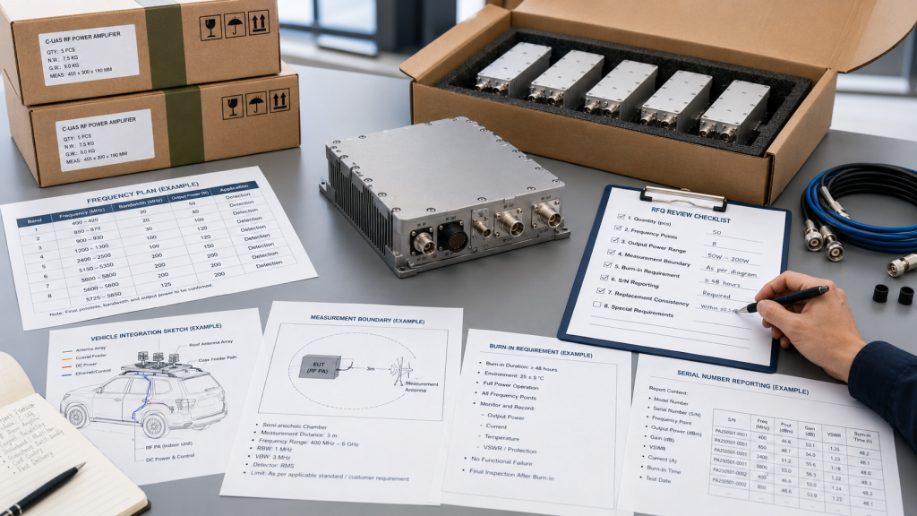
When selecting RF Power Amplifier modules for C-UAS integration, buyers should define output tolerance, serial-number reports, batch acceptance conditions, and replacement rules before final delivery approval.
1. What Rated Power Misses About RF Power Tolerance
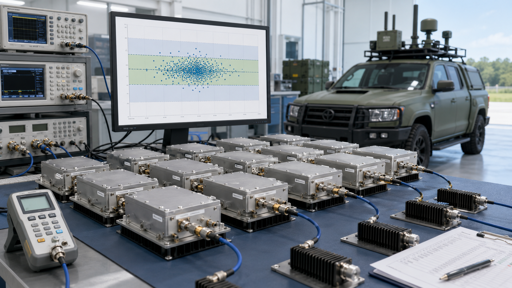
Batch RF power cannot be judged by one rated number because RF Power Tolerance is a controlled delivery range, not a promise that every unit will produce one identical watt value. A “100W” label defines the power class, but it does not describe the full batch distribution across frequency points, thermal states, and test boundaries.
Here’s the engineering point: small differences are normal in RF production because GaN devices, matching networks, PCB paths, connectors, thermal interfaces, and test setups all carry tolerances. The risk is not variation itself. The risk is uncontrolled, undocumented, or system-relevant variation.
What Does the Rated Number Actually Mean?
The rated number should be treated as a target category or contractual reference. It should not be used as the only batch acceptance rule.
Before judging a batch, define:
- Nominal output power
- Minimum guaranteed output
- Maximum controlled output
- Frequency points tested
- Measurement boundary
- Test voltage and load
- Temperature condition
- Serial-number report format
After deciding 100W vs 200W RF Power Amplifier selection, buyers should still define acceptable batch tolerance for that chosen power class.
Why Is Higher Output Not Automatically Better?
A module that reads higher than nominal may look attractive, but it can draw more current, generate more heat, or operate closer to protection limits. In a compact vehicle cabinet, that can become a thermal or supply risk.
Key Takeaway: Batch output should be approved by a defined tolerance range, not by whether every module lands on one rated watt number.
| Wrong Assumption | Better Check | Batch Risk |
|---|---|---|
| Every 100W unit must read exactly 100W | Define an output range | False rejection |
| Higher output is always better | Check current and heat | Hidden stress |
| Only low output is risky | Control maximum output too | Vehicle imbalance |
| One sample proves the batch | Review S/N reports | Missed outliers |
This table helps buyers move from rated-watt thinking to batch acceptance thinking.
2. When Is Output Power Variation Acceptable in Batch Delivery?
Output power variation is acceptable in batch delivery when RF Power Tolerance stays inside a defined minimum and maximum range, is measured under the same test conditions, and does not reduce vehicle-mounted C-UAS consistency. Variation becomes acceptable only when it is bounded, repeatable, and explainable.
The practical risk is clear: an undefined “small difference” becomes a dispute during vehicle integration. A defined tolerance becomes an engineering standard.
What Makes Variation Reasonable?
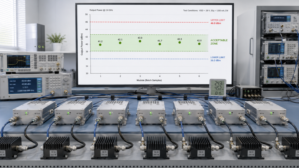
Variation is usually reasonable when all units remain above the minimum guaranteed output and below the maximum controlled output. The lower limit protects usable RF power, while the upper limit protects thermal, current, and protection margin.
Reasonable variation should meet these conditions:
- Same measurement boundary
- Same voltage reference
- Same load condition
- Same frequency points
- Same temperature state
- Same compensation method
- No abnormal current or alarm behavior
- No isolated outlier
For batch delivery, RF Power Amplifier batch burn-in helps connect output tolerance with S/N traceability and stress-screening evidence.
When Does Variation Become Risky?
Variation becomes risky when it changes vehicle behavior, creates channel imbalance, complicates replacement, or appears only at high-frequency edge points. A module can still pass a simple power check and still create system-level integration work.
Key Takeaway: Acceptable variation is not casual difference; it is measured, bounded, and harmless to the vehicle system.
| Variation Type | Usually Acceptable? | Why |
|---|---|---|
| Inside agreed range | Yes | Controlled by specification |
| Below minimum output | No | Reduces margin |
| Above maximum control limit | Not always | May add heat and current |
| One module far from batch | No | Possible outlier |
| Different test boundary | Cannot judge | Data is not comparable |
This table helps procurement reviewers separate normal tolerance from batch quality risk.
3. How to Define RF Power Tolerance for Batch PA Delivery
Acceptable RF Power Tolerance is defined by measurement boundary, frequency point, power class, test condition, system margin, minimum guarantee, maximum limit, and batch distribution. It cannot be judged by nominal wattage alone because the same power number means different things at the PA port, cabinet output, feeder end, or antenna input.
This is where system integrators should pay attention: tolerance is not one default value. It is a project-specific acceptance rule.
Which Factors Define the Tolerance Range?
A useful tolerance definition should include both RF and system variables. If one variable changes, the tolerance comparison may no longer be fair.
Define tolerance by:
- PA-port or cabinet-output reference
- Frequency points or sweep range
- 50W, 100W, 150W, or 200W power class
- Test voltage and module-end voltage
- Load and VSWR condition
- Temperature and run duration
- Minimum acceptable output
- Maximum controlled output
- Batch distribution and outlier rule
Before comparing tolerance, engineers should define RF Power Amplifier Output Power by measurement point so PA-port power, cabinet output, feeder-end power, and antenna-port power are not mixed.
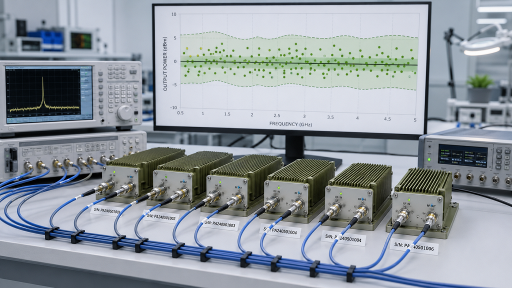
Why Should Frequency Be Separated?
A 900MHz point and a 5.8GHz point should not always share the same tolerance assumption. High-frequency paths are usually less forgiving, and edge-band output can show wider spread.
Tolerance should be checked by frequency because 5.8GHz RF Output may behave differently from lower bands after matching, feeder loss, heat, and measurement boundaries are included.
Key Takeaway: Acceptable tolerance is defined by test condition and system target, not by a supplier saying “about 100W.”
| Tolerance Factor | Why It Matters | Risk If Missing |
|---|---|---|
| Measurement boundary | Defines what power means | Wrong comparison |
| Frequency point | Finds band-specific spread | Hidden weak band |
| Minimum output | Protects system margin | Low-power delivery |
| Maximum output | Controls heat/current | Overstress risk |
| Batch distribution | Finds outliers | Poor replacement consistency |
This table helps buyers ask for a complete tolerance definition before accepting a batch.
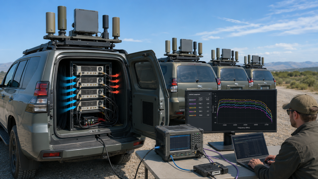
4. How Does RF Power Tolerance Affect Vehicle C-UAS Performance?
RF Power Tolerance affects vehicle-mounted C-UAS performance because module-to-module variation can change antenna-port power, channel balance, thermal load, supply demand, vehicle-to-vehicle consistency, and replacement behavior. A module that looks acceptable alone may create difficulty when installed across many vehicles.
Here’s the field reality: vehicle systems can amplify small differences. A few watts at the PA port can become a larger practical difference after feeder loss, antenna matching, cabinet heat, and DC supply variation.
Where Does Tolerance Become a System Issue?
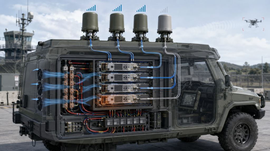
Vehicle-mounted C-UAS platforms often include multiple modules, roof antennas, compact cabinets, shared power paths, and limited service access. Batch variation can affect the whole integration.
Power tolerance can influence:
- Antenna-port usable output
- Multi-band channel balance
- Heat inside the cabinet
- Current draw from the vehicle supply
- Vehicle-to-vehicle repeatability
- Replacement module matching
- Customer acceptance comparison
In Low-Altitude Security & C-UAS EW Solutions, vehicle-mounted systems need batch power consistency because each vehicle should behave predictably after integration.
Why Does Antenna-Port Power Matter?
Even if modules fall within PA-port tolerance, vehicle feeder and connector paths can create additional differences. That is why batch tolerance should be reviewed together with RF Power Amplifier feeder and connector loss.
Key Takeaway: Batch tolerance matters because vehicle-level consistency depends on more than one module’s factory wattage.
| Module Difference | Vehicle-Level Effect | Better Review |
|---|---|---|
| Lower output unit | Less antenna-port margin | Check minimum output |
| Higher output unit | More heat and current | Check maximum limit |
| Band-specific spread | Channel imbalance | Review frequency data |
| Different vehicle readings | Fleet inconsistency | Compare full RF path |
| Replacement mismatch | Recalibration risk | Use S/N report range |
This table helps integrators connect module tolerance with real vehicle behavior.
5. How to Check RF Power Tolerance Across Vehicle C-UAS
Vehicle-mounted deployments reveal RF Power Tolerance problems because compact cabinets, vehicle power variation, roof antenna paths, vibration, and fleet-level integration can amplify small RF Power Amplifier output differences. The same batch that looks acceptable on a bench may become harder to manage when several vehicles must deliver similar RF behavior.
This is where vehicle C-UAS differs from fixed sites. A fixed site may optimize one cabinet, while a vehicle project may need multiple vehicles to remain comparable after installation, retest, and replacement.
Which Vehicle Conditions Expose Tolerance?
Vehicle platforms add mechanical, electrical, and RF-chain variables that make uncontrolled module variation harder to hide.
Important vehicle factors include:
- Compact PA cabinet space
- Roof antenna feedthroughs
- Vehicle-side DC variation
- Vibration and connector stress
- Multiple PA channels in one platform
- Short maintenance windows
- Fleet-level delivery comparison
Which Product-Level Context Matters?
Some vehicle projects use wideband platforms such as 300–2700MHz RF Power Amplifier modules where output tolerance must be reviewed across multiple bands rather than one convenient center frequency. For antenna-side consistency, C-UAS antenna matching also becomes part of final vehicle behavior.
Key Takeaway: Vehicle deployment turns batch tolerance into a fleet consistency issue, not only a factory data issue.
| Vehicle Condition | Tolerance Risk | Better Check |
|---|---|---|
| Compact cabinet | Heat difference matters | Review maximum output |
| Vehicle DC variation | Output may shift | Measure module-end voltage |
| Roof antenna path | PA tolerance becomes antenna difference | Include feeder path |
| Vibration | Connector behavior may change | Check mechanical stability |
| Fleet delivery | Vehicles must compare fairly | Use batch distribution |
This table helps buyers see why vehicle projects need clearer tolerance rules than one-off lab systems.
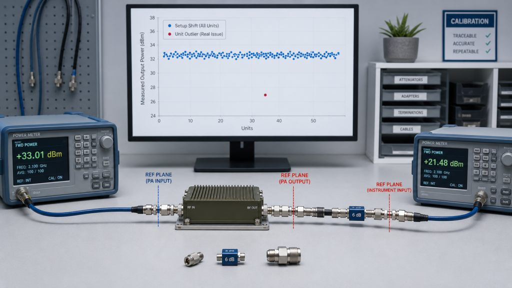
6. What Test Setup Changes RF Power Tolerance
Test setup can be mistaken for module tolerance because RF Power Tolerance changes with frequency, temperature, supply voltage, load condition, cable loss, measurement boundary, and instrument compensation. If these conditions are not controlled, the measured spread may describe the test setup rather than the RF Power Amplifier batch.
The better check is simple: control the test condition before judging the module batch.
Which Test Variables Change the Result?
A batch tolerance report should remove avoidable test variation. Otherwise, the buyer may confuse instrument or setup variation with module variation.
Control these variables:
- Frequency point and sweep range
- Module-end voltage
- Current capacity and supply ripple
- Load VSWR
- Cable and adapter loss
- Temperature and warm-up state
- Power meter reference plane
- Calibration and compensation method
Batch output comparison should also confirm RF Power Amplifier supply stability, because module-end voltage differences can look like output tolerance problems.
How Do You Separate Setup Shift from Unit Outlier?
If all modules shift in the same direction under a new test setup, check the setup first. Cable loss, reference plane, voltage, temperature, calibration, or compensation may have changed. If only one module breaks away from the batch distribution while the setup stays the same, review that module first.
For project planning, RF Power Amplifier frequency range selection should be aligned before tolerance is finalized, because tolerance at the wrong frequency does not help the vehicle system.
Key Takeaway: Batch tolerance is meaningful only when test conditions are controlled and when setup-wide shifts are separated from unit-specific outliers.
| Symptom | Better Starting Point | Likely Meaning |
|---|---|---|
| All units read lower in retest | Cable loss and reference plane | Setup difference likely |
| One unit reads low | S/N-specific data | Module review needed |
| High band spreads more | Frequency-point data | Band-specific tolerance issue |
| Hot units read lower | Thermal state | Temperature condition matters |
| Output follows voltage | Module-end voltage | Supply condition matters |
This table helps engineers avoid rejecting modules because the test setup changed.
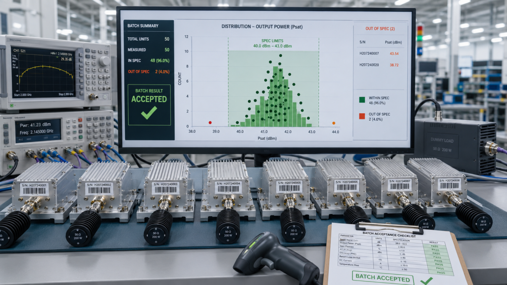
7. How Should Batch Acceptance Use Limits and Distribution?
Batch acceptance should use minimum output limits, maximum control limits, frequency-specific tolerance, distribution review, outlier screening, and serial-number traceability because RF Power Tolerance is a batch behavior, not a single pass/fail screenshot. A good batch should be stable, concentrated, and traceable.
The practical risk is clear: if you accept only by a few samples, you may miss the unit that creates the vehicle integration problem later.
What Limits Should Be Defined?
A useful batch acceptance method should define more than nominal wattage. It should tell the factory and customer how every unit will be judged.
Define:
- Minimum guaranteed output
- Maximum controlled output
- Typical expected range
- Frequency-specific range
- Outlier rule
- S/N report format
- Replacement matching rule
- Repair or retest rule
For batch delivery, post-burn-in output data from RF Power Amplifier batch burn-in can help confirm whether every delivered unit remains inside the accepted range after stress exposure.
Why Does Distribution Matter?
A batch where most units cluster tightly is easier to integrate than a batch where every unit barely passes but spreads widely. Distribution affects vehicle matching, maintenance, and future replacement.
Key Takeaway: Batch acceptance should judge both individual pass/fail and the overall distribution of delivered modules.
| Acceptance Element | What It Controls | Why It Matters |
|---|---|---|
| Minimum limit | Low output | Protects margin |
| Maximum limit | High output | Controls heat/current |
| Typical range | Batch center | Shows process stability |
| Outlier rule | Abnormal unit | Prevents field surprises |
| S/N data | Traceability | Supports vehicle matching |
This table turns batch acceptance from one wattage question into a controlled delivery process.
8. How to Prove RF Power Tolerance With S/N Reports
Reports and protection status should prove RF Power Tolerance by recording output power, voltage, current, frequency point, temperature, load condition, protection status, measurement boundary, and post-burn-in evidence for each serial number. A batch “Pass” label is not enough for vehicle C-UAS delivery.
Here’s the practical risk: if one vehicle behaves differently after integration, you need to know which module was installed, how it tested, and whether the output difference was accompanied by heat, current, VSWR, or voltage behavior.
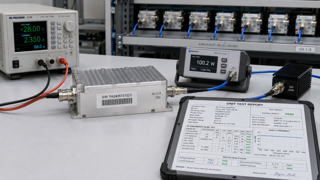
What Should One Report One Unit Include?
One Report One Unit matters because each module should carry its own evidence, not only a batch-level claim. The report should let the integrator match the physical module to the vehicle position and later maintenance record.
A useful unit-level report should include:
- Module S/N
- Model and frequency range
- Frequency points tested
- Output power by point
- Minimum and maximum limits
- Voltage and current
- Temperature state
- Load and VSWR condition
- Protection status
- Burn-in or post-burn-in output
- Measurement boundary
- Test date and equipment reference
Why Is Protection Status More Than a Safety Feature?
VSWR, temperature, and voltage protection are not only protective functions. They are diagnostic signals that help explain why one unit reads higher, lower, hotter, or more unstable than another.
Key Takeaway: Batch tolerance evidence should be unit-level, traceable, and diagnostic, not only a batch pass statement.
| Weak Evidence | Better Evidence | Why It Matters |
|---|---|---|
| Batch pass statement | S/N report per unit | Matches vehicle installation |
| One power screenshot | Frequency-point data | Finds weak bands |
| No voltage/current | Electrical records | Explains variation |
| No protection status | Alarm feedback | Finds boundary conditions |
| No post-burn-in result | Stress-state data | Improves shipment confidence |
This table helps buyers demand reports that support integration and maintenance, not only paperwork.
9. What RFQ Data Defines RF Power Tolerance
Before batch quotation, buyers should define RF Power Tolerance by batch quantity, frequency points, output range, measurement boundary, test conditions, S/N reports, post-burn-in data, protection status, and replacement consistency. Asking only “How many 100W modules can you deliver?” is not enough for vehicle C-UAS procurement.
This is where RFQ wording decides later acceptance quality. Clear input creates clear delivery evidence.
What Information Should Enter the RFQ?
The RFQ should define how the batch will be judged before production starts.
Share or request:
- Quantity and delivery schedule
- Same-batch or split-batch delivery
- Frequency bands and critical points
- Nominal output and minimum output
- Maximum controlled output
- Watt or dB tolerance format
- Measurement boundary
- Test voltage and load
- Temperature condition
- Burn-in requirement
- S/N report requirement
- Replacement matching rule
- Field retest boundary
Why Should Replacement Be Discussed Early?
Vehicle projects often need spare modules. If replacements are not matched to the same tolerance range, a maintenance action can become a new calibration problem.
As a source factory for RF Power Amplifier modules and C-UAS core components, RF SKYPOWER can support RFQ review by aligning batch output tolerance, frequency-specific test data, serial-number traceability, post-burn-in output, protection status, and repeatable shipment reports before final approval.
Key Takeaway: A strong RFQ defines how batch tolerance will be measured, reported, and used during vehicle integration.
| RFQ Item | Why It Matters | Risk If Missing |
|---|---|---|
| Batch quantity | Sets delivery control | Weak sampling logic |
| Frequency points | Defines real comparison | Wrong band tested |
| Output range | Creates pass/fail rule | Subjective dispute |
| S/N reports | Supports traceability | Hard maintenance |
| Replacement rule | Protects fleet consistency | Recalibration risk |
This table helps buyers turn output tolerance into a quotation and acceptance requirement.
10. How Do You Decide If Batch Output Tolerance Is Acceptable?
Batch output tolerance is acceptable only when every RF Power Amplifier module stays within defined minimum and maximum limits under the same test conditions, and the resulting RF Power Tolerance does not harm vehicle-level C-UAS consistency, power margin, or replacement reliability. The decision should be based on controlled evidence, not a clean-looking rated watt label.
This is the final review path: approve the batch only when the data supports both factory delivery and vehicle integration.
What Decision Sequence Should Engineers Use?
Use a structured sequence before final approval:
- Confirm nominal power and guaranteed minimum.
- Define PA-port, cabinet-output, or antenna-port boundary.
- Fix voltage, load, temperature, and test duration.
- Review frequency-specific tolerance.
- Check minimum and maximum output limits.
- Review batch distribution and outliers.
- Match S/N reports to shipment units.
- Include post-burn-in output if required.
- Check protection status and current behavior.
- Decide whether to ship, sort, retune, retest, or reject.
When Should the Batch Be Held?
Hold the batch if outliers appear, high-output units run hotter, low-output units reduce antenna-port margin, or report data cannot support customer retesting.
If your vehicle-mounted C-UAS project has not defined output tolerance, frequency-specific limits, serial-number reports, post-burn-in data, and replacement consistency, you can review your RF Power Amplifier output tolerance with a source-factory engineering team before final approval.
Key Takeaway: Acceptable tolerance is the range that keeps the vehicle system consistent, not the range that makes the factory report easiest to pass.
| If the Result Shows… | Start With… | Recommended Action |
|---|---|---|
| Tight stable distribution | Batch evidence | Approve if limits match |
| One low outlier | Frequency and voltage data | Retest or reject |
| One high hot unit | Current and temperature | Hold for review |
| Wide but passing spread | Vehicle matching plan | Sort or tighten range |
| Missing S/N report | Traceability | Request unit-level data |
This table gives engineering and procurement teams a final batch acceptance path.
FAQ
Can every RF Power Amplifier in a batch output exactly the same power?
No. Small variation is normal, but it must stay inside a defined tolerance range measured under the same conditions. The goal is controlled consistency, not impossible zero difference.
Is higher RF output always better in batch delivery?
No. Higher output can increase current draw, heat load, and protection risk. Batch approval should define both minimum output and maximum controlled output.
What should I check before accepting batch C-UAS PA modules?
Check nominal power, minimum output, maximum output, frequency points, measurement boundary, voltage, load, temperature, S/N reports, post-burn-in data, and protection status.
How do I know if batch power tolerance affects vehicle systems?
It matters when output spread changes antenna-port power, channel balance, vehicle-to-vehicle consistency, thermal margin, or replacement behavior. Compare module data with the full vehicle RF chain.
Should batch tolerance be measured at PA port or antenna port?
Start with a clearly defined PA-port or cabinet-output reference for module comparison, then evaluate antenna-port output if the vehicle RF path is part of acceptance. Do not mix the two boundaries.
Conclusion
Batch RF Power Amplifier delivery should not be judged only by a nominal watt value. In vehicle-mounted C-UAS systems, each module must fall within a defined output tolerance range, and that range must be measured under the same frequency point, voltage, load, temperature, measurement boundary, and test setup. A module that is slightly below nominal may still be acceptable if it meets the minimum guaranteed output, while a module that is far above nominal may create thermal, current, or protection risks.
For system integrators, RF engineers, and procurement reviewers, the practical lesson is clear: define RF Power Tolerance before batch delivery. Confirm minimum output, maximum control limit, frequency-specific tolerance, measurement boundary, test conditions, serial-number reports, post-burn-in data, protection status, and vehicle-level consistency requirements. Batch acceptance should be based on controlled evidence, not a single sample or one rated number.
RF SKYPOWER supports vehicle-mounted C-UAS batch delivery by connecting output tolerance, frequency testing, serial-number traceability, post-burn-in output, protection feedback, and repeatable shipment reports before final project approval. If your team needs to align batch tolerance, vehicle RF paths, supply margin, antenna-port targets, and replacement rules before ordering RF modules, you can discuss your project with RF SKYPOWER before final delivery requirements become difficult to change.
Batch C-UAS delivery should be approved by controlled tolerance evidence, not by a clean-looking rated watt label.