











Large-venue C-UAS frequency strategy should be defined before RF PA selection. The project must first establish its authorized target frequencies, protected or conditionally controlled frequencies, venue zones, antenna sectors, operating states, RF power reference planes, and acceptance boundaries.
All target, protected, excluded, and conditional frequencies must come from the customer’s lawful operating authority, applicable spectrum rules, and the approved venue coordination plan.
In this article, protected bands means project-defined frequencies or services that require exclusion, operating restrictions, filtering, or additional coordination. The term does not replace local regulatory classifications.
RF Power Amplifier Modules should be evaluated only after the venue plan defines what each RF path must support. PA bandwidth alone does not determine which signals are generated, filtered, routed, enabled, or delivered to a particular antenna sector. Those functions depend on the complete RF architecture.
This article focuses on large venues and temporary high-density sites. Detailed drone-link mapping, general frequency-range selection, control-state design, and complete acceptance testing remain separate engineering reviews.
Once those venue-level boundaries are approved, the broader RF power amplifier module selection workflow should confirm signal drive, usable output, duty cycle, 28 V DC, RF-path, control, protection, and evidence requirements.
1. Why Large-Venue Frequency Strategy Must Come Before RF PA Selection
A frequency list is not yet a frequency strategy.
A valid strategy must also define:
- which bands are authorized in each venue zone;
- which frequencies require exclusion or conditional control;
- which signals may operate simultaneously;
- which antenna sector belongs to each RF path;
- where the required RF power will be measured;
- which operating states require verification;
- whether future bands justify current hardware reserve.
These decisions may affect the number of RF paths, filter arrangement, switch structure, antenna layout, DC demand, cooling capacity, control interface, and acceptance plan.
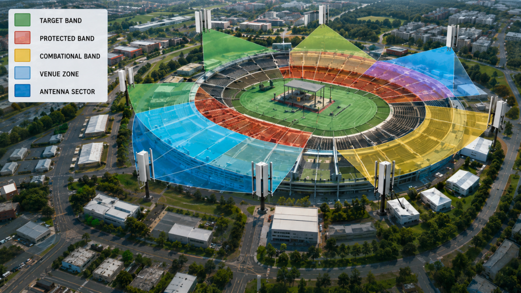
Large venues create changing operating boundaries
Large venues may include:
- central event areas;
- outer perimeter sectors;
- service and loading zones;
- public-access areas;
- temporary media or production zones;
- emergency-service areas;
- temporary command positions.
The same PA platform may require different antenna sectors, output limits, operating states, or acceptance boundaries across these zones.
One RF path may be authorized only for a defined sector. Another may remain inhibited until a specific operating condition is approved. Temporary antenna placement may also change feeder loss, antenna matching, or the PA-port margin required to deliver the specified RF power.
Temporary installations require site-specific approval
A temporary deployment may change:
- cabinet position;
- available 28 V DC capacity;
- feeder routing;
- antenna mounting;
- airflow;
- ambient condition;
- authorized local communications.
The RF PA may support the required frequency range at its output, but the installed system still needs defined antenna paths, control states, load conditions, and acceptance evidence for the actual venue.
Hardware capability and venue-specific approval should therefore be treated as separate boundaries.
2. What the Strategy Must Define Before Hardware Is Chosen
The project should first identify its authorized frequency requirements and organize them into engineering groups.
Detailed link analysis can begin by mapping required links to RF PA frequency coverage. The venue strategy then converts those frequency groups into spatial, operating, and hardware requirements.
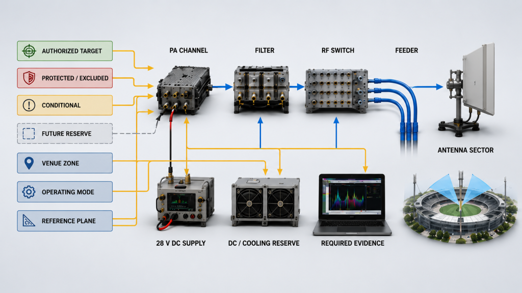
Target frequencies
For each authorized target group, define:
- actual frequencies or sub-bands;
- priority;
- required RF power;
- measurement reference plane;
- duty cycle;
- operating mode;
- antenna sector;
- simultaneous-operation requirement;
- acceptance evidence.
Do not define a target only as a broad catalog frequency range. The required project points should be visible in the RFQ and test plan.
Protected, excluded, and conditional frequencies
Project-defined protected frequencies may require:
- complete exclusion;
- restricted operating states;
- filter boundaries;
- time- or zone-based control;
- additional spectrum coordination;
- system-level verification.
The PA does not independently recognize or avoid these frequencies.
The complete RF path must enforce the approved boundary through:
- signal generation;
- filtering;
- switching;
- gain and enable control;
- antenna assignment;
- operating permissions;
- spectral verification.
A conditional frequency should also have a defined activation rule. Its use may depend on venue authorization, time window, antenna sector, control state, or installed filter path.
Reserve frequencies should influence current hardware only when the project has a documented RF PA expansion requirement beyond common drone bands. Undefined future possibilities should not automatically force every current channel into the widest PA platform.
Venue zones and antenna sectors
Every important frequency group should be assigned to a complete RF path.
Define:
- venue zone;
- antenna sector;
- PA or channel assignment;
- filter and switch path;
- feeder route;
- required RF power reference plane;
- permitted operating state.
| Strategy Field | Project Decision | Hardware Consequence | Evidence Required |
|---|---|---|---|
| Target frequency | Required frequency or sub-band | PA and RF-path assignment | Frequency-specific result |
| Protected or excluded frequency | Prohibited or restricted condition | Filtering, routing, and control boundary | System-level verification |
| Conditional frequency | Authorized activation condition | Enable, inhibit, or switching requirement | State-specific evidence |
| Venue zone | Physical area or sector | Antenna and feeder assignment | Installed-path record |
| Operating mode | Sequential, multi-carrier, or independent simultaneous channels | DC, thermal, linearity, filtering, and control requirement | Mode-specific result |
| Measurement reference plane | PA output, cabinet output, feeder end, or antenna input | Required RF margin | Defined measurement boundary |
| Future reserve | Confirmed upgrade requirement | Space, DC, cooling, and control reserve | Expansion decision record |
This boundary matrix should be completed before individual PA models are compared.
3. How Protected Frequencies and Venue Sectors Change the RF Architecture
Protected-frequency requirements and venue sectors do not automatically select one PA frequency range. They define the boundaries that the complete RF architecture must follow.
The resulting design may require:
- separate RF paths;
- frequency-specific filters;
- switched antenna sectors;
- independent gain or enable control;
- different output limits by zone;
- sequential rather than simultaneous operation;
- separate evidence for different operating states.
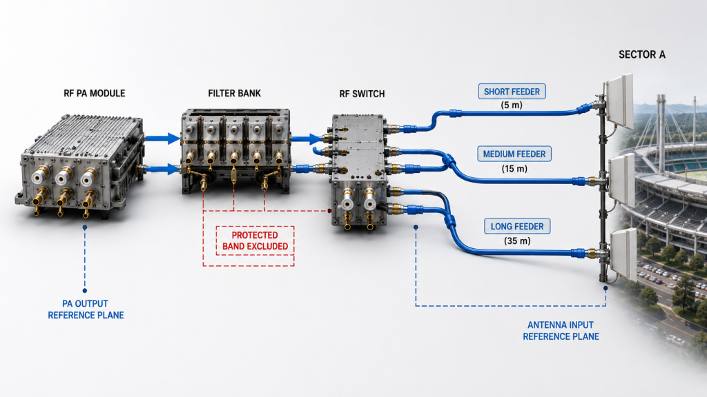
A broad PA range does not remove system boundaries
A wideband PA may support several required frequencies, but those frequencies may still require separate filters, switches, antennas, or control states.
Separate downstream paths may be necessary because of:
- different operating permissions;
- antenna bandwidth;
- sector isolation;
- filter requirements;
- different RF power targets;
- simultaneous-channel requirements.
Wideband hardware provides useful flexibility only when the rest of the RF chain can use that flexibility under defined and verifiable conditions.
Venue sectors change the required RF margin
One zone may use a short feeder and directional antenna. Another may use a longer feeder, a different mounting position, or a more difficult load condition.
These differences can change:
- feeder loss;
- RF power delivered to the antenna input;
- reflected power;
- VSWR behavior;
- PA-port output required to meet the installed result.
If a path requires higher PA-port output, longer duty cycle, or operation under a poorer load condition, it may also increase DC and thermal demand.
For each sector, record:
- Required frequency group
- Assigned PA or RF channel
- Filter and switch path
- Feeder and antenna assignment
- Required RF power and reference plane
- Operating mode
- Acceptance limit
Once these boundaries are approved, the project can move into RF PA frequency-range selection using the defined bands, paths, output targets, duty cycle, and evidence requirements.
4. How Control, Filtering, and Antenna Paths Enforce the Strategy
A venue strategy becomes operational only when the hardware and control system can enforce it.
The integrator does not need to complete every software function before PA procurement. However, the control and interface requirements that affect hardware selection must already be defined.
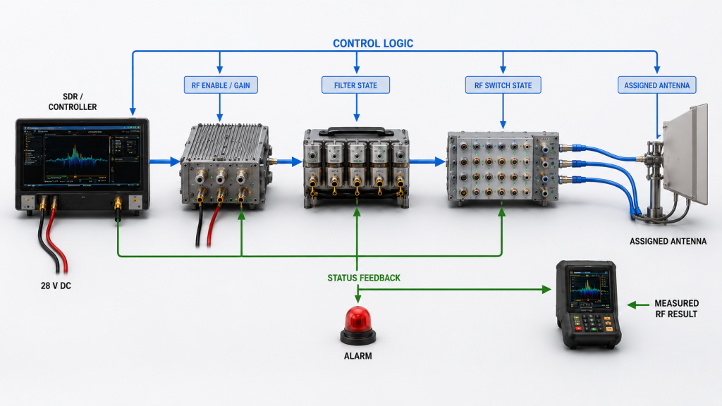
Control requirements
Before purchase, define:
- module or channel addressing;
- enable and inhibit requirements;
- gain or power-control requirements;
- switch and antenna assignment;
- operating-state confirmation;
- status and alarm visibility;
- protection-state handling;
- control-interface type;
- hardware and control-version boundary.
These requirements can later be translated into detailed RF power amplifier control logic for system integration.
A command record alone is not sufficient. The project should confirm that the commanded state matches:
- the active PA or channel;
- the selected filter;
- the assigned antenna path;
- the expected RF result;
- the reported status.
Filtering requirements
Filters may be required to:
- limit the active passband;
- suppress out-of-path emissions;
- separate adjacent RF paths;
- support a defined spectral boundary;
- meet antenna, combiner, or switch requirements.
Filtering alone does not prove coexistence with an authorized service inside the same active band.
Where frequencies overlap or cannot be separated by filtering, the project may also require:
- inhibit rules;
- frequency coordination;
- antenna isolation;
- output limits;
- time-based control;
- zone-based control;
- additional operating approval.
The RFQ should identify whether filtering is:
- integrated with the PA assembly;
- installed externally in the cabinet;
- part of a switched filter bank;
- assigned to an individual antenna path;
- supplied by the system integrator.
A module-level PA report may prove PA performance without proving the final filtered RF path.
Antenna-path requirements
For each antenna path, define:
- supported frequency range;
- polarization;
- sector role;
- feeder type and length;
- connector and bulkhead count;
- expected VSWR boundary;
- installation position;
- required RF power delivered to the antenna input.
The PA-output result and antenna-input result are not interchangeable.
The procurement document must identify both the required RF power and the measurement reference plane for each critical path.
5. What Evidence Proves the Hardware Follows the Strategy
The strategy review should focus on evidence that can change the hardware architecture or prevent approval of the proposed RF path.
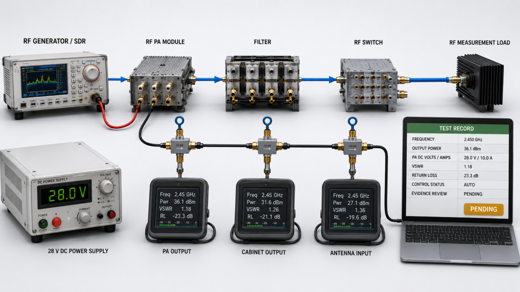
Frequency and path evidence
For each critical path, record:
- assigned frequencies;
- PA or channel;
- operating mode;
- measurement reference plane;
- required RF result;
- hot-state duration;
- module-input voltage and current;
- load or VSWR boundary;
- filter and control state;
- evidence status.
A center-frequency screenshot is not enough where approval depends on a band edge, filter transition, difficult antenna match, or installed-path loss.
Simultaneous-operation evidence
The RFQ must state whether simultaneous signals:
- share one PA and RF path; or
- use independent RF channels.
A shared multi-carrier path may require evidence for:
- composite output power;
- peak-to-average power ratio;
- compression;
- linearity;
- intermodulation products;
- spectral regrowth;
- total DC and thermal load.
Independent simultaneous RF paths may require evidence for:
- port-to-port isolation;
- antenna coupling;
- filter interaction;
- combiner or switch behavior;
- shared DC and cooling load;
- control and protection response.
Testing each channel only in isolation may not prove that the approved simultaneous combination is usable.
Module-level and installed-path responsibility
Module-level testing establishes the PA baseline.
Final venue approval may also require evidence through:
- cabinet connectors;
- filters;
- switches;
- feeder cables;
- antenna interfaces;
- representative or installed loads.
The RFQ should define which evidence belongs to the module supplier and which belongs to the system integrator.
Final delivery records should remain traceable to the supplied model, serial number, hardware version, control version, and report revision. However, the strategy review should first focus on evidence that can change the RF architecture.
| Band / Zone | Assigned Path | Operating Mode | Measurement Reference Plane | Required Evidence | Status |
|---|---|---|---|---|---|
| Primary target band / sector | PA, filter, feeder, and antenna path | Sequential, multi-carrier, or independent channel | PA output, cabinet output, feeder end, or antenna input | Frequency, hot-state, load, and control-state result | Pass / Open |
| Secondary target band / sector | Assigned RF path | Defined operating mode | Defined reference plane | Required path-level evidence | Pass / Open |
| Protected or excluded frequency | Filter, routing, and control boundary | Inhibited or restricted state | System-level boundary | Filter, spectral, control, or coordination evidence | Pass / Open |
| Conditional frequency / zone | Assigned conditional path | Authorized activation state | Defined reference plane | State-specific RF and control evidence | Pass / Open |
| Future reserve | Reserved space, DC, cooling, and control path | Not active in current phase | Future requirement | Documented expansion boundary | Documented / Open |
The final project matrix should replace these generic entries with actual authorized frequencies, zones, paths, limits, and responsibilities.
RFQ Checklist: What to Define Before RF PA Purchase
Before requesting a final quotation, provide:
- venue type and deployment duration;
- authorized target frequencies;
- protected, excluded, and conditional frequencies;
- venue zones and antenna sectors;
- sequential, multi-carrier, and independent simultaneous combinations;
- required RF power and measurement reference plane;
- feeder, filter, switch, connector, and antenna-path assumptions;
- duty cycle and hot-state duration;
- available 28 V DC and cooling capacity;
- control, alarm, and protection interface;
- required module-level and installed-path evidence.
A request containing only a frequency range and wattage does not define enough information for architecture approval.
The supplier should be able to explain:
- Which frequency group belongs to each RF path
- Which paths may operate simultaneously
- Where the required RF power is measured
- Which filtering and control boundaries apply
- Which evidence is supplied by the module manufacturer and which remains the system integrator’s responsibility
Conclusion
Large-venue C-UAS frequency strategy should convert lawful operating requirements into clear RF-path boundaries before PA selection begins.
A broad PA range cannot compensate for undefined routing, unclear operating permissions, missing antenna assignments, or incompatible measurement boundaries. Target frequencies, venue sectors, operating modes, filtering, control, and evidence responsibility must be defined as one architecture.
Send the authorized frequency groups, venue zones, antenna sectors, operating combinations, required RF power and measurement reference planes, installed-path assumptions, 28 V DC and cooling limits, control requirements, and the required acceptance evidence.
RF SKYPOWER can review how those inputs should translate into RF PA path assignments, filtering requirements, antenna paths, control interfaces, and test-report boundaries before the hardware configuration is locked.