


Choosing RF Power Amplifier Modules for a C-UAS system is not only a question of rated watts or frequency range. A module that looks suitable on a datasheet may still fail the real project if output power, duty cycle, VSWR protection, cooling path, antenna load, control interface, and test data are not checked together.
The central conflict is simple: a datasheet describes the module under defined conditions, but a C-UAS system tests the module inside a complete RF chain. For system integrators, RF amplifier modules are core RF components that must match target bands, platform size, 28V supply, cabinet layout, antenna path, thermal condition, protection logic, and acceptance evidence before they can be trusted inside a deployed counter-UAS system.
This selection guide explains how engineers should compare RF Power Amplifier modules for C-UAS systems by frequency range, usable output, duty cycle, VSWR behavior, cooling method, control feedback, supplier support, and repeatable test reports.
1. What Are RF Power Amplifier Modules in C-UAS?
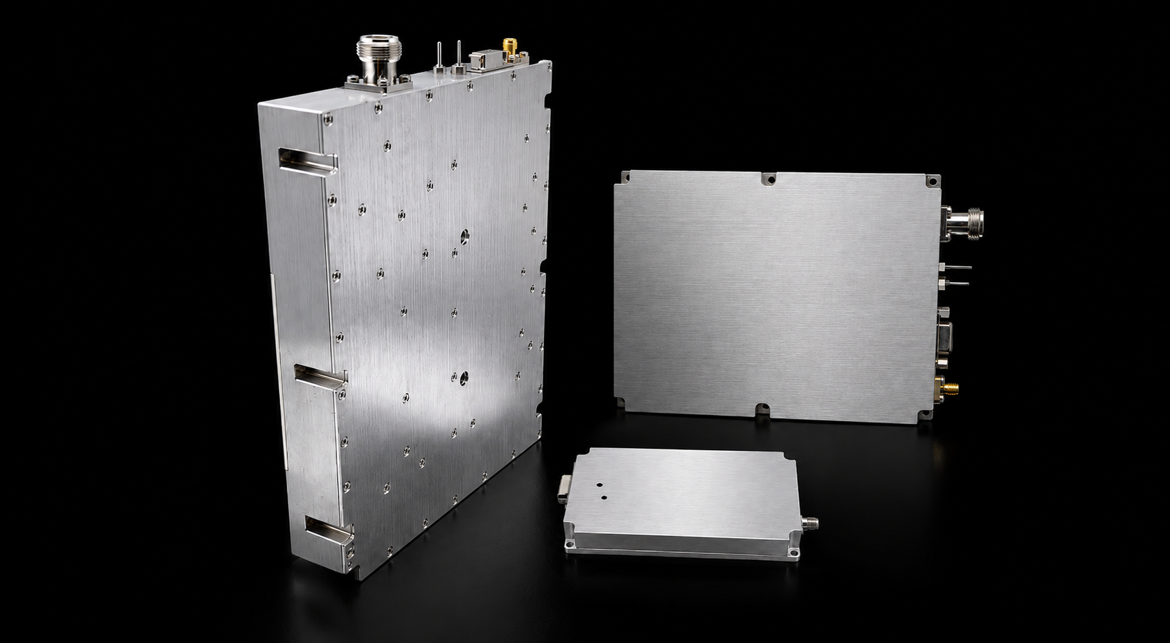
RF Power Amplifier Modules in a C-UAS system is the core RF chain component that turns a controlled signal source into usable high-power output. It is not a complete counter-UAS system by itself, and it should not be judged as an isolated power part. Its real value depends on frequency range, duty cycle, load condition, cooling, protection, control, and test evidence.
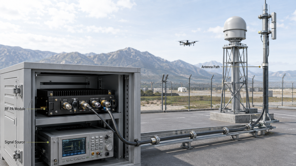
Here’s the engineering point: a PA module sits between the signal source and the deployed RF path. If the rest of the system cannot support the same frequency, power, heat, protection, and antenna conditions, the module rating alone does not prove system performance.
What role does the module play in the RF chain?
A C-UAS transmit chain may include a signal source, SDR, RF PA module, filters, switches, feeder cables, antennas, DC power, cooling hardware, and control logic. The module’s job is to amplify the defined RF signal to the required output level without losing stability under the expected system conditions.
Engineers comparing RF Power Amplifier modules should start with frequency range, output power, duty cycle, protection logic, cooling method, and test data before requesting a quotation.
Why is it not the same as a complete C-UAS system?
A module is a core component, not a finished system. The system integrator still needs to decide how the module will be driven, cooled, powered, controlled, protected, and connected to antennas.
In Low-Altitude Security and C-UAS EW systems, RF module selection should be based on the full RF chain, not only on a standalone amplifier datasheet.
Key Takeaway: RF PA module selection starts by understanding the module’s role inside the full C-UAS RF chain, not by comparing one wattage number.
| Wrong Assumption | Better Check |
|---|---|
| “The module is the whole system.” | Confirm signal source, control, power, cooling, and antenna path. |
| “Higher power means better system effect.” | Check usable output after load, heat, and feeder conditions. |
| “A datasheet range proves coverage.” | Verify target-frequency output and antenna compatibility. |
| “Protection is optional.” | Confirm VSWR, temperature, voltage, and alarm behavior. |
This table helps separate module selection from complete system validation.
2. How to Choose RF Power Amplifier Modules by Frequency
An RF Power Amplifier Module frequency range should be selected from the C-UAS mission bands first, then verified by target-frequency output, thermal behavior, antenna-path compatibility, and repeatable test data. Frequency range is usually the first selection filter, but it is not the final proof of suitability.
The practical risk is clear: a module may cover the required band on paper, yet still be weak at the edge, difficult to cool, mismatched with the antenna path, or unsupported by test evidence at the exact frequencies the project needs.
How should low, mid, and high bands be grouped?
A useful frequency plan should separate required bands by mission role, antenna path, power target, and platform design. Low-band, mid-band, and high-band RF paths may require different module types, cooling expectations, antenna structures, and acceptance checks.
When the system requires low-band, VHF, UHF, or tactical low-frequency coverage, a 30–512MHz RF Power Amplifier Module can be reviewed as a low-band path, but the final decision still depends on output target, platform size, antenna load, cooling, and test data.
When do wideband and narrowband modules make sense?
Wideband RF PA modules can reduce module count and support multi-band integration, but they require stronger evidence for gain flatness, thermal behavior, edge output, and antenna-path matching. Narrowband modules may offer more focused performance in a specific band, but they provide less flexibility if the frequency plan changes.
For broad low-to-mid band C-UAS architectures, a 300–2700MHz RF Power Amplifier Module may reduce the number of PA paths, while a 300–1700MHz RF Power Amplifier Module may fit more compact mid-low integrations. If the project includes high-band paths, a 2000–6000MHz RF Power Amplifier Module should be evaluated together with feeder loss, antenna matching, thermal load, and hot-state test evidence.
Key Takeaway: The right frequency range is the one that matches real C-UAS target bands and can be verified under the installed RF chain, not simply the widest label.
| Frequency Decision | Useful When | Selection Risk |
|---|---|---|
| Low-band module | Low-frequency C-UAS coverage is required | Larger antenna and cabinet impact |
| Mid-band module | Common multi-band C-UAS integration is needed | Edge output and heat must be checked |
| High-band module | High-frequency links are part of the plan | Feeder loss and antenna path become sensitive |
| Wideband module | Fewer PA paths are preferred | Flatness and thermal proof are essential |
| Narrowband module | One band is clearly defined | Future flexibility may be limited |
This table helps engineers choose frequency range by system role instead of catalog width.
3. How Much Output Should RF Power Amplifier Modules Have
An RF Power Amplifier Module needs enough usable output after feeder loss, antenna load, duty cycle, thermal derating, and protection behavior are included. The highest rated wattage on a datasheet is not automatically the best choice, because higher output also increases current demand, heat load, cabinet pressure, and VSWR risk.
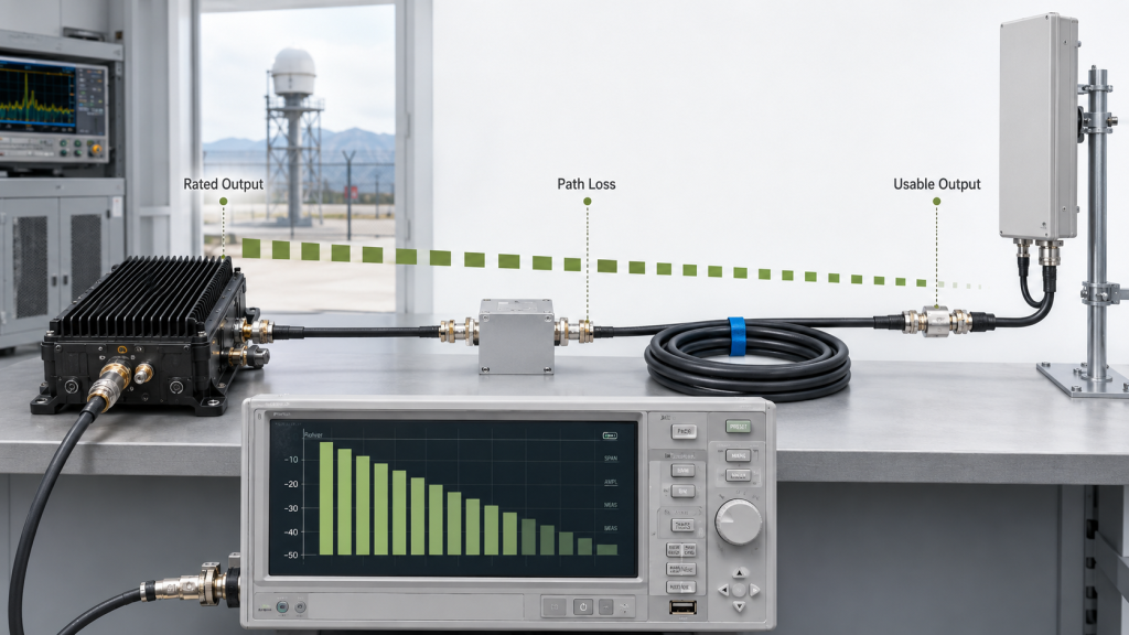
This is where system integrators should pay attention: rated output describes what the module can produce under defined conditions, while usable output describes what remains useful inside the real C-UAS RF path.
How should rated output and usable output be compared?
Rated output is the module-side number. Usable output is the output that still matters after cable loss, connector loss, switching loss, antenna mismatch, thermal behavior, and DC supply conditions are included.
A deeper RF Power Amplifier Output Power review should compare rated output with usable C-UAS output after feeder loss, antenna load, thermal margin, and duty cycle are included.
When is more power not the better choice?
More power can be useful when the antenna path, power supply, cooling method, and protection logic can support it. It can become a problem when the platform cannot remove heat, the DC rail cannot support current, or the antenna path creates reflected power.
Engineers should also define whether the project needs portable output, vehicle-mounted output, fixed-site output, or long-duty infrastructure output before comparing 50W, 100W, 150W, or 200W options.
Key Takeaway: Output power selection should protect the system target, not simply maximize the module label.
| Power Question | Better Engineering Check |
|---|---|
| “Should I choose 50W, 100W, or 200W?” | Define antenna-end target and margin first. |
| “Is higher power safer?” | Check heat, supply current, VSWR, and duty cycle. |
| “Can one module cover all needs?” | Review frequency band, antenna path, and platform limits. |
| “Can the rating be trusted?” | Request target-frequency and hot-state output data. |
This table helps engineers avoid treating wattage as a standalone purchasing shortcut.
4. Why Does Duty Cycle Change RF PA Module Selection?
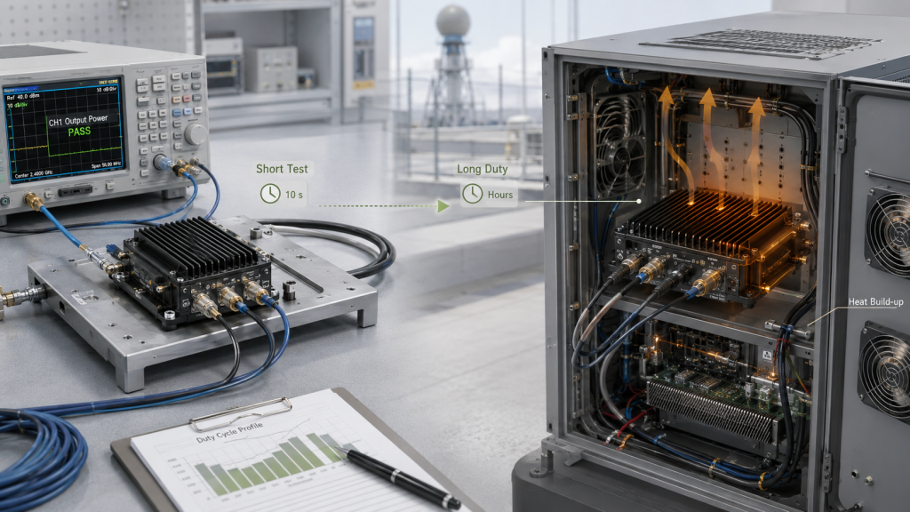
Duty cycle changes RF Power Amplifier Module selection because short RF output, intermittent operation, and long-duration C-UAS duty place very different stress on heat, current, protection, stability, and lifetime. A module that reaches rated output during a short factory check may not be suitable for a long-duration fixed-site, vehicle-mounted, or outdoor cabinet profile.
The field reality is simple: a short reading proves output at one moment, but C-UAS operation often requires repeatable output under heat, load, and time.
What should duty cycle mean in the RFQ?
Duty cycle should describe how long the module must operate, how often it cycles, how much heat builds inside the cabinet, and whether the system expects continuous or intermittent output. A vague request such as “100W RF amplifier module” does not provide enough thermal or reliability context.
A useful RFQ should include:
- Expected output duration
- Continuous or intermittent operation
- Ambient temperature
- Cabinet airflow
- Heat sink condition
- Supply voltage range
- Protection-state reporting
- Hot-state test requirement
Why does short testing create false confidence?
Short testing may confirm that the module can reach power, but it does not prove that the module can hold power without thermal derating, alarm events, or output drift. This gap becomes more visible when the system moves from a bench check to a sealed cabinet, rooftop installation, vehicle platform, or fixed perimeter site.
Key Takeaway: Duty cycle turns RF PA selection from a wattage question into a heat, supply, protection, and lifetime question.
| Duty Profile | Selection Risk | Better Check |
|---|---|---|
| Short burst | Power may look strong | Still check VSWR and current |
| Intermittent use | Heat may recover between cycles | Define cycle timing |
| Long-duty operation | Heat builds inside cabinet | Request hot-state data |
| Continuous output | Thermal path becomes critical | Confirm cooling and derating |
| Batch operation | Variation may appear across units | Require S/N-linked reports |
This table helps match the module to the real operating profile instead of a short demo condition.
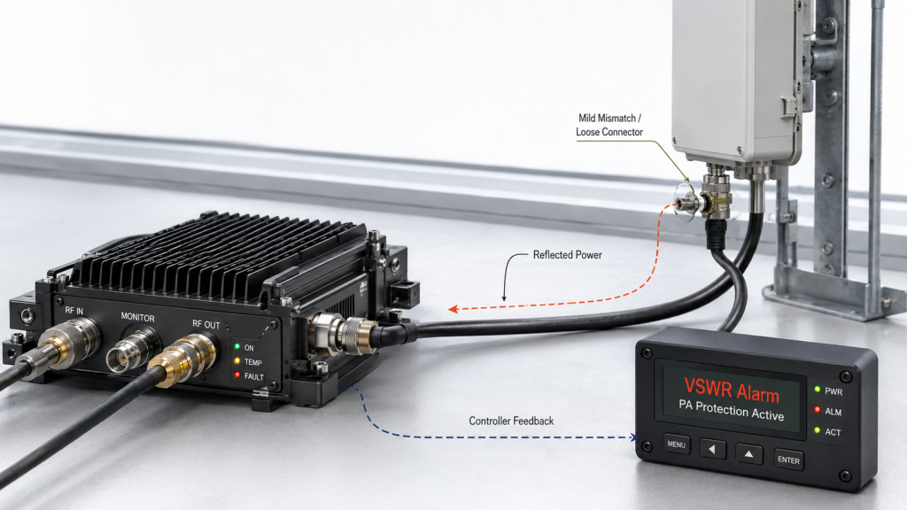
5. What VSWR Protection Should Engineers Check Before Buying?
Engineers should check VSWR protection before buying an RF Power Amplifier Module because C-UAS antennas and feeder paths can change in the field. The amplifier must detect reflected power, report faults, reduce risk, and protect itself before damage occurs.
The practical risk is clear: VSWR protection is not just a checkbox. A module may claim protection, but the system still needs to know how the alarm is triggered, how the module responds, and how the controller sees the fault.
What questions should buyers ask about VSWR protection?
A useful supplier discussion should cover more than “yes” or “no.” Engineers should ask:
- Does the module detect reflected power?
- Does it provide a VSWR or reflected-power alarm?
- Does it reduce output or shut down?
- Can the controller read the fault state?
- How does the module recover?
- Is the protection state recorded in test data?
- Does VSWR protection interact with temperature or voltage protection?
Why does protection not replace antenna matching?
Protection reduces damage risk, but it does not turn a poor antenna path into good coverage. A mismatched antenna can still reduce usable output, trigger alarms, heat connectors, or create unstable field behavior.
The better check is to review VSWR protection together with antenna match, feeder loss, connector quality, mechanical strain, and field installation conditions.
Key Takeaway: VSWR protection should be treated as part of system survivability, not as permission to ignore the antenna and feeder path.
| Protection Item | Why It Matters |
|---|---|
| Reflected-power detection | Identifies load mismatch risk |
| Alarm output | Makes the fault visible to the controller |
| Auto-reduction or shutdown | Protects the PA under severe mismatch |
| Recovery behavior | Prevents unclear restart conditions |
| Test record | Shows the protection was not only claimed |
| Status feedback | Helps field troubleshooting |
This table helps buyers compare protection behavior, not just protection wording.
6. What Cooling Do RF Power Amplifier Modules Need?
Cooling method should be evaluated before RF Power Amplifier Module purchase because usable C-UAS output depends on the full thermal path from RF device, copper spreading, housing, heat sink, airflow, cabinet, and ambient temperature. A module can only sustain output if heat can leave the device fast enough under the actual duty cycle.
Here’s the engineering point: heat is not managed by one part. It moves through a chain, and the weakest point in that chain can force derating.
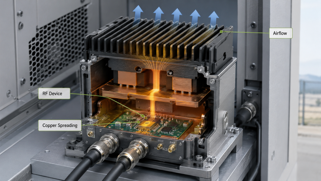
What parts of the thermal path should be checked?
Engineers should review the full heat path rather than only asking whether the module has a heat sink. Important checks include:
- Device-to-base heat transfer
- Copper spreading or heat-distribution design
- Housing contact surface
- Thermal pad or grease condition
- External heat sink size
- Forced-air cooling
- Cabinet airflow
- Ambient temperature
- Temperature alarm
- Hot-state output test
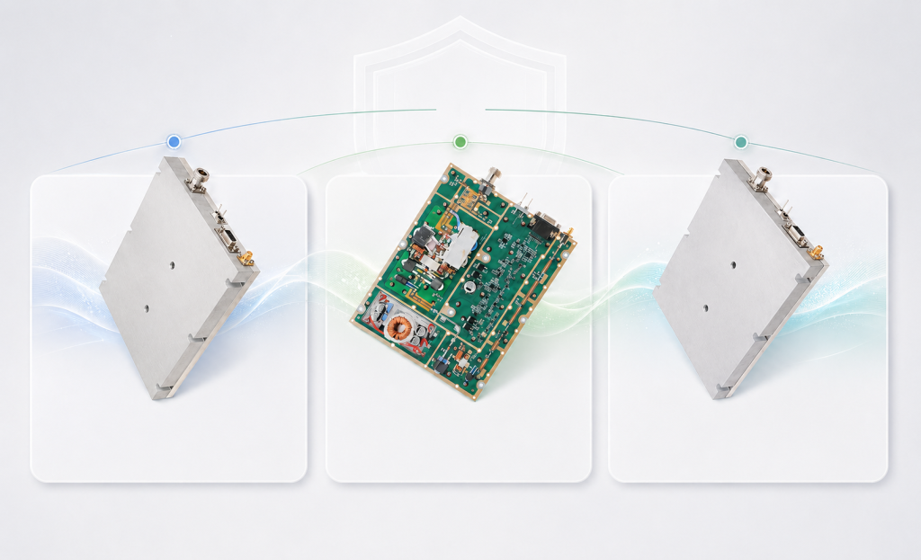
A Broadband RF Power Amplifier module should be selected by verified installed behavior, not only by frequency range or rated wattage, because wideband operation can expose heat, gain, and edge-frequency limits at the same time.
Why is cabinet integration part of cooling?
The module supplier may test with a defined heat sink or open airflow, while the integrator installs the module inside a dense cabinet. Cable routing, nearby modules, blocked airflow, dust, and high ambient temperature can all change real thermal behavior.
Cooling should therefore be checked together with duty cycle, power level, module spacing, external heat sink, fan path, copper spreading, and temperature-protection feedback.
Key Takeaway: Cooling evaluation should connect module design to the actual cabinet, platform, duty cycle, and ambient environment.
| Thermal Condition | Selection Risk | Better Check |
|---|---|---|
| Small cabinet | Heat accumulates | Review airflow and spacing |
| High duty cycle | Output may derate | Request hot-state data |
| Poor mounting surface | Heat transfer weakens | Check flatness and interface |
| High ambient site | Less thermal margin | Confirm temperature protection |
| Dense multi-module rack | Local hot spots appear | Review layout and air path |
This table helps engineers treat cooling as a system path instead of a heat sink size.
7. What Control Interface and Feedback Should Be Required?
Control interface and protection feedback should be required before RF Power Amplifier Module purchase because C-UAS systems need to enable, monitor, protect, reset, and diagnose each amplifier path during real integration. A module that performs well on the bench can still slow system delivery if the control signals do not match the cabinet controller.
This is where integration teams often lose time: the RF output works, but the system cannot read alarms, sequence enable timing, or identify which PA channel has entered protection.
What interface items should be checked?
A practical interface review should include:
- Enable and disable logic
- Alarm output
- Temperature alarm
- VSWR alarm
- Voltage alarm
- Power adjustment
- Gain control
- Reset behavior
- Analog or digital feedback
- Connector type
- Protocol or command support
- Fault recovery logic
RF Power Amplifier control interface planning helps integrators manage enable timing, alarm feedback, thermal response, VSWR status, and fault recovery before the module becomes part of a multi-channel cabinet.
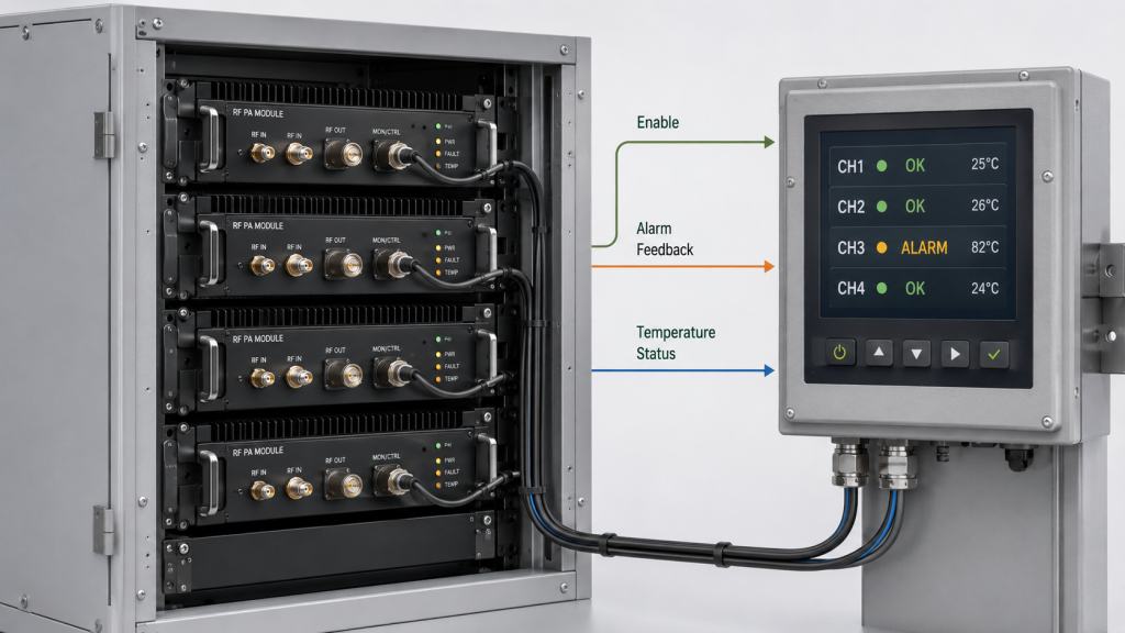
Why does feedback matter in multi-module C-UAS cabinets?
In a multi-band C-UAS cabinet, the controller should know which module is active, which channel has alarmed, and whether output is limited by heat, voltage, or reflected power. Without feedback, field troubleshooting becomes guesswork.
A simple power-on signal may be enough for a basic prototype, but a serious C-UAS integration often needs alarm visibility, fault recovery behavior, and channel-level status.
Key Takeaway: Control interface is not a secondary detail; it decides whether the RF module can become a manageable system channel.
| Control Requirement | Why It Matters |
|---|---|
| Enable timing | Prevents wrong startup sequence |
| Alarm feedback | Shows fault state to the controller |
| VSWR status | Helps identify antenna-path problems |
| Temperature status | Shows thermal stress before failure |
| Reset logic | Defines recovery after protection |
| Communication support | Helps system-level monitoring |
This table helps buyers compare integration readiness rather than only RF output.
8. How to Check RF Power Amplifier Modules Test Data
An RF Power Amplifier Module is ready for C-UAS integration only when its frequency output, thermal behavior, current draw, VSWR status, duty-cycle stability, and S/N-linked test data can be reviewed under realistic system conditions. A datasheet is useful, but it is not the same as delivery evidence.
The better check is simple: ask whether the test data matches your intended operating condition. If your project needs wideband output, long-duty operation, high-power fixed-site deployment, or batch delivery, a single clean test point is not enough.
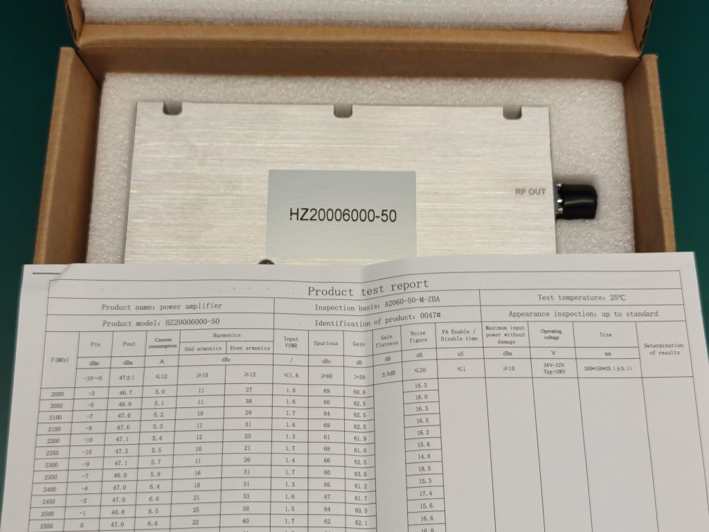
What should useful test data include?
A practical C-UAS test package may include:
- Target-frequency output
- Gain and drive level
- Supply voltage and current
- Module temperature
- Efficiency or current trend
- VSWR or reflected-power status
- Harmonic or spurious behavior
- Duty-cycle condition
- Hot-state output
- Burn-in result
- S/N-linked report
- Test setup condition
Why does S/N-linked reporting matter?
Sample data can support early evaluation, but delivered modules should still be traceable when a project depends on batch consistency. S/N-linked reports help engineers compare unit behavior, investigate field issues, and reduce after-sales disputes.
As a source factory for RF Power Amplifier modules and C-UAS core components, RF SKYPOWER can support clearer engineering communication by tying module data, load condition, protection status, and repeatable test evidence into one acceptance discussion.
Key Takeaway: Test data should prove the module under the same frequency, thermal, duty, load, and protection assumptions that the system will use.
| Weak Evidence | Better Evidence |
|---|---|
| Datasheet only | Target-frequency test data |
| One center-frequency point | Low, center, high, and project-critical points |
| Cold short test | Hot-state output result |
| Output only | Output plus current, temperature, and VSWR |
| Sample report only | S/N-linked unit report |
| No setup details | Test condition and reference point |
This table helps procurement reviewers separate marketing specifications from acceptance evidence.
9. What RF Power Amplifier Modules Supplier Support Matters?
Engineers should compare RF Power Amplifier Module suppliers by engineering support, test transparency, customization ability, protection logic, thermal review, batch traceability, and system-integration response—not only by price and rated power. C-UAS RF PA module procurement is not a one-time parts purchase; it is often an engineering collaboration.
The selection risk appears here: if the supplier cannot explain the test condition, protection behavior, interface logic, thermal path, or batch control, the integrator may discover the gap only during system integration.
What support should a source factory provide?
A source factory can support module selection with:
- Frequency range review
- Custom band discussion
- Output level recommendation
- Control interface adjustment
- Housing or connector customization
- Thermal path review
- Protection logic explanation
- Test report generation
- Batch traceability
- Field issue analysis
RF SKYPOWER supports wideband and narrowband RF amplifier modules, CNC housings, copper heat spreading, VSWR / temperature / voltage protection, control-interface customization, and S/N-linked test reports for C-UAS system integration.
How should trading suppliers be evaluated fairly?
A trading supplier is not automatically unsuitable, but the buyer should confirm whether they can provide engineering answers beyond price and delivery. If they cannot support test review, customization, failure analysis, or protection explanation, the technical risk increases.
The better comparison is not “factory versus trader” as a slogan. It is whether the supplier can answer the engineering questions that appear during integration, retesting, field troubleshooting, and repeat orders.
Key Takeaway: Supplier comparison should focus on engineering evidence and support depth, not only catalog speed or unit price.
| Supplier Question | Why It Matters |
|---|---|
| Is the module self-developed or resold? | Clarifies engineering access |
| Can test data be explained? | Supports acceptance review |
| Can the frequency range be adjusted? | Helps custom C-UAS projects |
| Can protection logic be documented? | Reduces integration uncertainty |
| Is batch traceability available? | Supports repeat orders and dispute analysis |
| Who supports field troubleshooting? | Defines after-sales responsibility |
This table helps buyers evaluate supplier risk before the RFQ becomes a purchase order.
10. How to Finalize RF Power Amplifier Module Selection for C-UAS?
Final RF Power Amplifier Modules selection for C-UAS should combine frequency range, usable output, duty cycle, antenna path, cooling, protection, control interface, test data, and source-factory support before moving to product-page comparison or RFQ. A good final selection process prevents the buyer from choosing a module that looks strong but cannot be integrated, cooled, controlled, or verified.
Here’s the final decision point: you are not buying only a module. You are choosing whether that module can become a stable RF channel inside your real C-UAS architecture.
What final checklist should engineers use?
Before quotation, prepare:
- C-UAS scenario
- Target frequency range
- Required usable output
- Duty cycle
- Antenna and feeder path
- Cooling and cabinet condition
- VSWR, temperature, and voltage protection needs
- Control interface requirement
- Test report expectation
- Quantity and customization needs
- Platform size and weight limits
- Acceptance reference point
If the requirement is still broad, the RF Power Amplifier Modules page can help you compare available frequency and power options before engineering review.
How should product-page comparison be used?
Product-page comparison should come after the project has a basic selection boundary. For example, low-band requirements may start with the 30–512MHz module series, broad low-to-mid band coverage may point to the 300–2700MHz module series, compact mid-low integration may fit the 300–1700MHz module series, and high-band paths may require the 2000–6000MHz module series.
These product pages should not replace engineering review. They should help engineers narrow the candidate module family before checking target frequency points, thermal margin, antenna load, control interface, and test-report requirements.
Key Takeaway: Final selection should turn the module from a product option into a verified system component.
| Selection Condition | Recommended Path |
|---|---|
| Frequency range uncertain | Define target bands first |
| Low-band requirement | Review low-band module options and antenna size |
| Broad mid-band requirement | Compare wideband PA paths and hot-state data |
| High-band requirement | Check feeder loss and antenna matching carefully |
| Power level uncertain | Estimate usable output and margin |
| Duty cycle unknown | Confirm operation profile |
| Control interface undefined | Confirm enable, alarms, and feedback |
| Evidence weak | Request target-frequency and S/N-linked reports |
This table gives buyers a practical path from commercial investigation to RFQ.
FAQ
Can I choose an RF PA module only by frequency range?
No. Frequency range is only the first filter. You also need to check target-frequency output, duty cycle, antenna path, VSWR protection, cooling method, control interface, and test data.
What’s the best RF Power Amplifier Module for C-UAS?
The best module is the one that fits your frequency range, usable output, duty cycle, platform size, antenna path, thermal condition, protection requirements, and acceptance evidence. There is no universal best module for every C-UAS system.
How do I know if I need a wideband RF amplifier module?
Choose a wideband module when your system needs multi-band coverage and can support the required thermal, antenna, control, and test conditions. Do not select wideband hardware only because it looks more flexible on paper.
What should I check before buying high-power RF amplifier modules?
Check usable output, current draw, cooling method, VSWR protection, duty cycle, antenna load, control interface, and hot-state test data. High power without thermal and protection margin can create integration risk.
When should I ask for S/N-linked test reports?
Ask for S/N-linked reports when the project involves high power, batch delivery, fixed-site deployment, multi-band coverage, or strict acceptance. They help compare delivered units and support future troubleshooting.
Conclusion
RF Power Amplifier Module selection for C-UAS systems should combine frequency range, usable output, duty cycle, antenna path, VSWR protection, cooling method, control interface, test data, and source-factory engineering support. The right RF PA module is not simply the widest or highest-power option; it is the module that can be installed, cooled, controlled, protected, tested, and verified under the project’s real operating conditions.
For system integrators, the practical path is clear. Define the required frequency range, output target, duty cycle, antenna condition, cooling path, control interface, and test-report expectations before asking for price or delivery time. That information allows a source-factory team to recommend a module series that fits the system, not only the datasheet.
As a source factory for RF Power Amplifier modules and C-UAS core components, RF SKYPOWER can support frequency review, output selection, cooling discussion, protection logic, control-interface alignment, customization, and repeatable test reporting before final approval. If your team is comparing RF amplifier modules for a C-UAS project, you can review your RF module requirements with RF SKYPOWER before locking the product series or cabinet design.
Field-ready C-UAS integration starts with verified RF module decisions, not catalog shortcuts.