


Broadband and narrowband RF Power Amplifier Modules should be compared by system architecture, not by frequency range labels alone. A broadband module can support flexible multi-band coverage, fewer PA paths, and future frequency margin, while a narrowband module can be easier to optimize for a fixed target band, higher efficiency, clearer filtering, and more predictable thermal behavior. The better choice depends on target frequencies, usable output, duty cycle, antenna path, cooling condition, protected-band boundaries, and test evidence.
The central conflict is simple: broadband coverage solves flexibility, while narrowband design solves band-specific optimization. A broadband RF Power Amplifier Module may reduce cabinet complexity and support future expansion, but it may also require stronger proof for output flatness, efficiency, band-edge behavior, hot-state stability, and full-band test evidence. A narrowband RF PA module may look less flexible, but it can be more practical when the project has fixed target bands, tight thermal limits, strict filtering needs, or simple acceptance requirements.
This article compares broadband vs narrowband RF Power Amplifier Modules for C-UAS system selection. It explains when broadband helps, where it can lose efficiency or output flatness, why narrowband is not a lower-grade option, how duty cycle and RF path affect the decision, and what full-band or target-frequency test evidence engineers should request before purchase.
1. What Is the Difference Between Broadband and Narrowband RF PA Modules?
A broadband RF Power Amplifier Module covers a wider operating frequency range, while a narrowband RF PA module is optimized around a smaller target band. The difference is not “advanced versus outdated.” It is a difference between coverage flexibility and band-specific optimization.
A broadband module may support several target bands in one hardware path, which can reduce module count, cabinet wiring, and future redesign pressure. A narrowband module focuses engineering effort on a smaller range, which can make output, matching, filtering, efficiency, and thermal behavior easier to control.

What does each design solve?
Here’s the engineering point: the better module depends on what problem the system is trying to solve.
Broadband modules usually help when the system needs:
- Multi-band C-UAS coverage
- Future frequency margin
- Fewer PA paths
- Faster cabinet integration
- More flexible system architecture
Narrowband modules usually help when the system needs:
- Fixed-band performance
- Higher band-specific efficiency
- Clearer filtering
- Simpler thermal behavior
- Easier target-frequency acceptance
Engineers comparing RF Power Amplifier Modules should treat broadband and narrowband options as architecture choices, not only as product categories.
Key Takeaway: Broadband solves coverage flexibility, while narrowband solves fixed-band optimization; the better choice depends on the system’s real RF plan.
| Selection Question | Broadband Direction | Narrowband Direction |
|---|---|---|
| Are several bands required? | Often stronger fit | More modules may be needed |
| Is one band fixed? | May be overbuilt | Often stronger fit |
| Is cabinet space limited? | Can reduce module paths | Can increase paths |
| Is efficiency critical? | Must be proven by band | Easier to optimize |
| Is future expansion likely? | Usually helpful | Limited flexibility |
This table helps buyers avoid treating broadband as automatically better or narrowband as automatically weaker.
2. When Does a Broadband RF Power Amplifier Module Help C-UAS Systems?
A broadband RF Power Amplifier Module helps C-UAS systems when multi-band coverage, future frequency margin, cabinet simplification, and faster integration matter more than single-band optimization. This is common when the project must support several target bands or when the frequency plan may evolve.
The practical value is clear: one broader PA path can sometimes replace multiple narrow paths. That can reduce cabinet space, connectors, control lines, switching paths, and spare-part complexity. But that benefit is real only if the target frequency points have usable output and thermal evidence.

Where does broadband create real system value?
Broadband is worth evaluating when the project has these conditions:
- Multiple C-UAS target bands
- Uncertain future frequency needs
- Limited cabinet space
- Need for fewer module SKUs
- Fast integration schedule
- Upgrade margin requirement
- Common control architecture
A wider frequency label should still be treated as the starting point, not the final proof. If only one clean point is shown, the buyer still does not know whether the rest of the band is usable.
When does broadband become commercial value?
For a system integrator, broadband can reduce layout complexity and simplify procurement. For a technical buyer, it can reduce redesign risk when new target bands are added later. For an RF engineer, it can reduce handoff points between modules.
Key Takeaway: Broadband helps when flexibility is valuable, but every target frequency still needs evidence.
| Broadband Benefit | Why It Helps | What Still Needs Proof |
|---|---|---|
| Fewer PA paths | Simpler cabinet | Output at target points |
| Wider coverage | More flexible planning | Full-band behavior |
| Future margin | Easier upgrades | Thermal reserve |
| Fewer SKUs | Easier sourcing | Batch consistency |
| Faster integration | Less wiring complexity | Antenna-path match |
This table shows why broadband is an architecture advantage only when the usable RF behavior is proven.
3. Where Can Broadband RF PA Modules Lose Efficiency or Flatness?
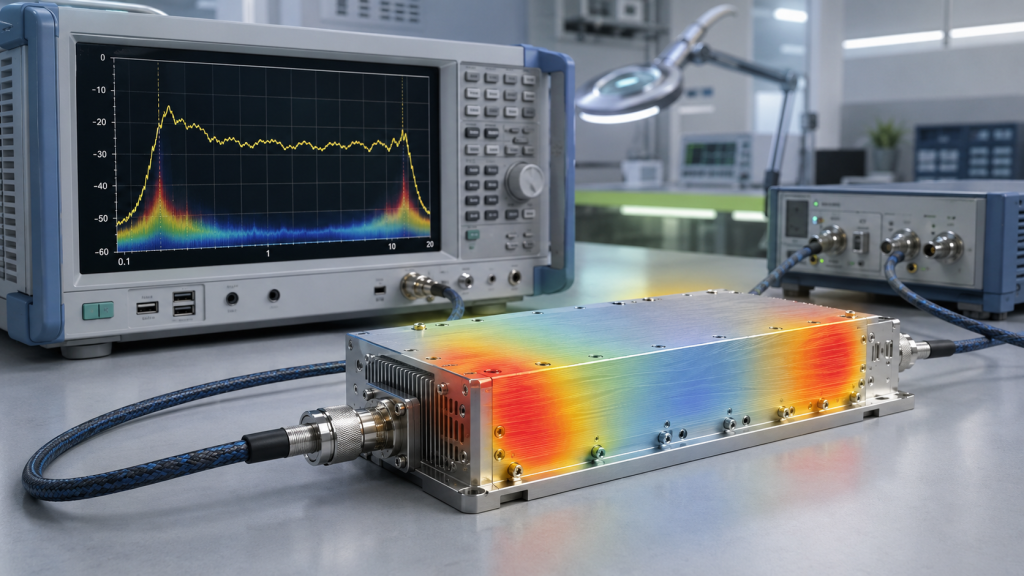
A broadband RF Power Amplifier Module can lose efficiency or output flatness because wide frequency coverage forces the amplifier to balance matching, gain, thermal behavior, drive level, and stability across many operating points. A wide label does not prove equal output at the low edge, center, high edge, and project-critical bands.
This is where buyers should be careful. Broadband coverage is useful, but broadband output flatness must be proven. One strong frequency point does not prove full-band performance.
What makes broadband flatness difficult?
Wideband design must balance several variables at once:
- Matching network behavior
- Device efficiency by frequency
- PCB layout and parasitic effects
- Input drive differences
- Heat distribution
- VSWR sensitivity
- Band-edge behavior
- Load condition
Gain flatness testing helps engineers check whether amplification remains consistent across low, center, high, and target frequency points. However, gain flatness is not the same as output power flatness; final output still depends on drive, load, voltage, heat, and protection behavior.
Why are band edges sensitive?
The low and high ends of a broadband range often reveal the design margin. A module can look stable in the middle of the band but show lower output, higher current, or more heat near the edge. Band-edge performance should therefore be checked before approving a broadband path for full-band C-UAS coverage.
Key Takeaway: Broadband output should be treated as a measured curve, not a flat promise.
| Broadband Claim | Possible Risk | Better Evidence |
|---|---|---|
| Wide frequency range | Uneven output | Frequency-point data |
| High center output | Weak edge output | Low/center/high tests |
| Stable gain | Output still varies | Output power sweep |
| Good short test | Thermal drift later | Hot-state data |
| One target passes | Other points unknown | Target-point report |
This table helps buyers challenge wideband claims without dismissing broadband value.
4. When Is a Narrowband RF PA Module the Better Choice?
A broadband RF Power Amplifier Module is not always the better choice; a narrowband RF PA module can be stronger when the target band is fixed, output efficiency matters, thermal margin is limited, protected-band boundaries are strict, and future frequency flexibility is not the main requirement.
The selection risk appears here: if the project only needs one narrow target band, buying broadband may add cost, testing burden, filtering complexity, and thermal uncertainty that the project does not need. In that case, narrowband is not a lower-grade option. It is a more focused option.

Where does narrowband create value?
Narrowband design may be a better fit when the project has:
- Fixed target frequency
- Stable platform requirement
- High duty cycle
- Tight thermal limit
- Strict protected-band boundary
- Known antenna path
- Simple acceptance scope
- Lower need for future expansion
Because the design range is smaller, matching and filtering can be more focused. That may support better efficiency, clearer output margin, and simpler heat behavior under the right conditions.
Why should buyers still request evidence?
Narrowband does not remove the need for testing. A narrowband module still needs output, VSWR, temperature, voltage, current, and duty-cycle evidence at the required operating point. The difference is that the evidence can be more focused.
Key Takeaway: Narrowband can be the better choice when the project rewards focused performance more than frequency flexibility.
| Project Condition | Better Fit May Be | Why |
|---|---|---|
| One fixed band | Narrowband | More focused optimization |
| Many bands | Broadband | Fewer PA paths |
| High duty cycle | Depends on heat data | Efficiency matters |
| Strict protected band | Narrowband or filtered path | Easier boundary control |
| Future expansion likely | Broadband | More frequency margin |
This table helps procurement teams choose by project conditions rather than by product fashion.
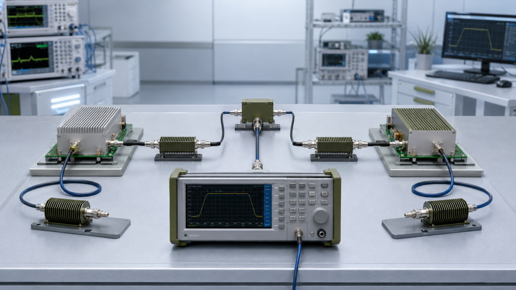
5. How Should Engineers Compare Broadband and Narrowband Output Power?
A broadband RF Power Amplifier Module and a narrowband RF PA module should be compared at the target frequency points, under the same drive, voltage, load, duty cycle, thermal condition, and output reference point. Rated wattage alone is not enough.
A 100W broadband module and a 100W narrowband module may not behave the same at the exact frequency the project needs. The broadband module may offer more flexibility, while the narrowband module may offer stronger margin at a fixed band. You cannot judge that from the model title alone.
What output data should be compared?
The better check is simple: compare like with like.
Engineers should request:
- Output at target frequency points
- Input drive condition
- DC voltage and current
- Load condition
- Duty cycle
- Thermal state
- VSWR or reflected power
- Measurement reference point
- Whether loss compensation is included
Rated output power should be converted into usable C-UAS output before broadband and narrowband modules are compared. PA-port output, feeder-end output, and antenna-port output cannot be mixed as if they describe the same result.
Why does usable output matter?
Usable output is what remains after feeder loss, connector loss, switching path, filter loss, antenna mismatch, heat, and protection behavior are included. Broadband and narrowband options should be judged at the same system boundary.
Key Takeaway: Output comparison is fair only when frequency point, condition, and reference plane are the same.
| Wrong Comparison | Better Comparison |
|---|---|
| Rated wattage vs rated wattage | Target-frequency output vs target-frequency output |
| PA-port data vs antenna data | Same reference point |
| Cold short test vs hot long test | Same duty and thermal condition |
| One broadband point vs one narrowband point | All project target points |
| Datasheet label vs test report | Condition-based evidence |
This table helps buyers avoid choosing the wrong architecture from mismatched numbers.
6. How Do Duty Cycle and Cooling Change the Decision?
A broadband RF Power Amplifier Module may be attractive for frequency flexibility, but duty cycle and cooling can change the broadband versus narrowband decision. Frequency flexibility is useful only when the module can maintain stable output through the real thermal path and operating duration.
Here’s the field reality: short demonstrations and long-duty C-UAS operation are not the same selection boundary. A module that works during a short test may behave differently inside a cabinet, vehicle platform, or fixed site after heat builds.
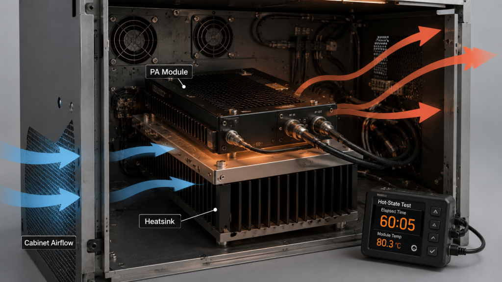
What thermal questions should be asked?
Engineers should check:
- Expected duty cycle
- True CW or intermittent operation
- Worst-case frequency point
- Current draw by frequency
- Heat sink condition
- Airflow path
- Cabinet ambient temperature
- Temperature protection threshold
- Hot-state output data
Broadband modules may have different efficiency across the band, so the hottest frequency point may not be the same as the strongest output point. Narrowband modules can be easier to optimize thermally, but high-power narrowband operation still needs serious heat management.
Where can source-factory input help?
As a source factory for RF Power Amplifier modules and C-UAS core components, RF SKYPOWER can support engineering review by checking target frequency points, usable output, duty cycle, antenna path, cooling condition, VSWR behavior, and repeatable test evidence before final module approval.
Key Takeaway: Thermal behavior can make the theoretically flexible option less practical if the duty cycle is heavy and the cooling path is tight.
| Operating Condition | Selection Risk | Better Check |
|---|---|---|
| Short test only | Heat problem hidden | Hot-state test |
| High duty cycle | Current and heat rise | Duty-cycle data |
| Wideband operation | Worst point unclear | Multi-point thermal data |
| Tight cabinet | Airflow limited | Cabinet heat review |
| Fixed band | Narrowband may help | Efficiency comparison |
This table helps engineers include heat as a selection condition, not an afterthought.
7. How Do Antenna, Feeder, and Filter Paths Affect the Choice?
A broadband RF Power Amplifier Module or narrowband RF PA module can only be judged correctly when the antenna bandwidth, feeder loss, filter path, switch architecture, and output reference point are included in the comparison. The PA module is not the whole RF chain.
The practical risk is clear: a broadband module may cover a frequency that the antenna path does not support. A narrowband module may perform well on a dummy load but fail when the installed antenna mismatch raises reflected power. Both choices can fail if the RF path is ignored.

What RF-chain variables should be checked?
Engineers should review:
- Antenna bandwidth
- Antenna gain and pattern
- Feeder length
- Connector count
- Adapter transitions
- Filter passband
- Protected-band boundary
- Switch or combiner path
- Output reference point
- VSWR or reflected-power status
In Low-Altitude Security & C-UAS EW systems, broadband and narrowband RF PA modules should be compared by installed RF behavior, not only by frequency range.
Why does filtering matter?
Broadband modules may need more careful filtering or control boundaries, especially near protected channels. Narrowband modules may be easier to filter, but they can require more paths if several target bands are needed.
Key Takeaway: The real comparison is PA plus RF chain, not PA alone.
| RF-Chain Item | Broadband Risk | Narrowband Risk |
|---|---|---|
| Antenna bandwidth | PA covers more than antenna | Antenna too narrow for drift |
| Feeder loss | High-band output reduced | Still affects target output |
| Filter path | More complex boundaries | Less flexible |
| Switch path | Fewer modules may help | More paths may be needed |
| VSWR behavior | Varies by frequency | Still must be checked |
This table helps system integrators compare installed performance instead of catalog performance.
8. How Should Full-Band Testing Be Done for Broadband Modules?
A broadband RF Power Amplifier Module should be tested across low-edge, center, high-edge, target-frequency, hot-state, and antenna-path conditions instead of relying on one clean output point. Full-band testing does not mean every project must test every possible frequency step, but it does mean the critical points must be proven.
This is where broadband selection becomes serious. If a module is purchased because it is wideband, the report should show how that wideband behavior was verified.
What points should the test include?
A practical broadband test plan should include:
- Low edge
- Center point
- High edge
- Project target points
- Known high-heat points
- Known high-loss points
- Protected-adjacent points
- Transition or overlap points
- Antenna-path reference where required
A broadband mid-band RF PA path can simplify multi-band architecture, but full-band and target-frequency evidence should still define where the output remains usable. A high-band RF PA path should be checked at target high-band points, band edges, feeder paths, and hot-state conditions before C-UAS approval.
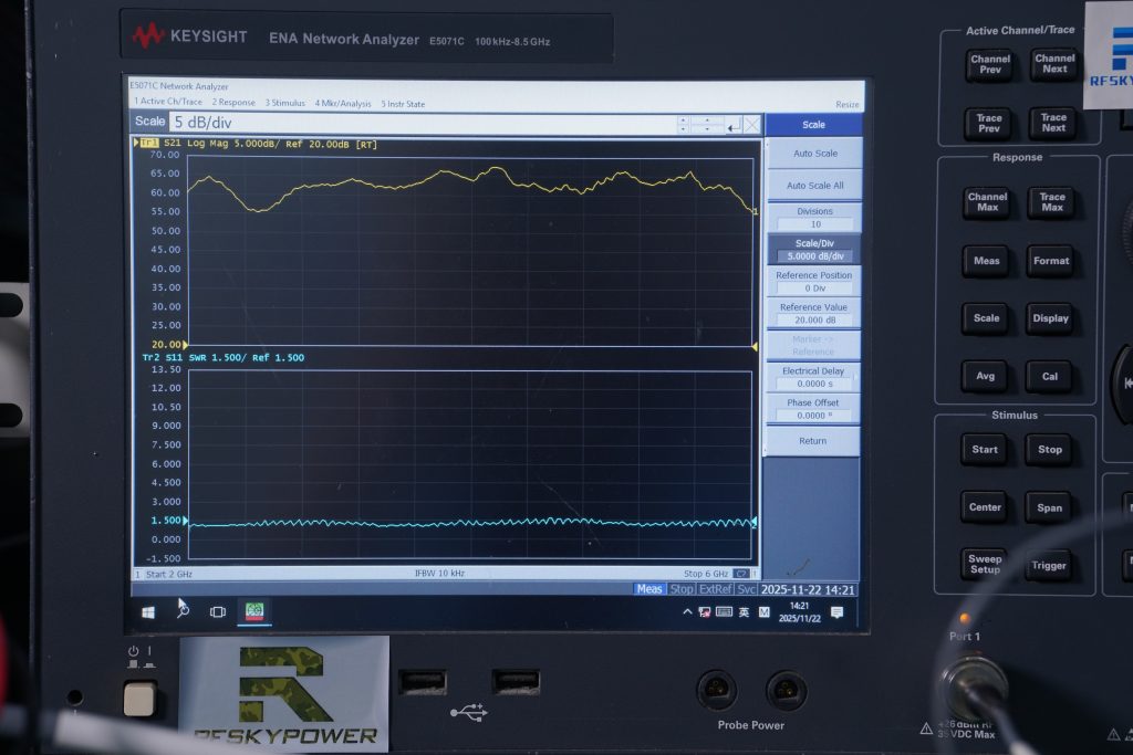
What should the report show?
Useful fields include output power, gain, input drive, DC voltage, current, temperature, load condition, VSWR, reflected power, duty cycle, test duration, cooling condition, and pass/fail boundary.
Key Takeaway: Full-band testing should prove the real broadband operating window, not just the nicest point in the band.
| Test Point | Why It Matters | Weak Alternative |
|---|---|---|
| Low edge | Shows lower boundary behavior | Center-only test |
| High edge | Shows upper boundary behavior | Mid-band assumption |
| Target points | Matches project need | Generic sweep only |
| Hot-state points | Reveals thermal drift | Cold short test |
| Antenna path | Shows installed behavior | PA-port only |
This table helps buyers request evidence that matches the reason they are buying broadband.
9. How Should Engineers Build a Commercial Comparison Table?
A broadband RF Power Amplifier Module should be compared with a narrowband RF PA module through a commercial table that includes usable coverage, output margin, efficiency, cooling, protection, control, test evidence, and expansion—not only price and rated band.
Many purchasing tables are too thin. They list frequency range, output power, price, and lead time, but they miss the evidence that decides whether the module will work in the real C-UAS architecture. A lower unit price is not always cheaper if it creates extra RF paths, cooling changes, late filtering work, repeated test disputes, or redesign after acceptance review.
What should the table include?
A serious comparison table should include:
- Target frequency output
- Full-band behavior
- Gain or output flatness
- Efficiency
- Current draw
- Thermal behavior
- Duty cycle
- VSWR protection
- Over-temperature protection
- Over-voltage protection
- Control interface
- Antenna compatibility
- Cooling requirement
- Size and weight
- Test report
- Customization support
- Production consistency
In FPV swarm defense scenarios, multi-band frequency behavior can make broadband RF PA modules attractive, but each target band still needs output and thermal evidence.
How does the table guide purchasing?
The table should not choose “the strongest module.” It should choose the module that best matches the RF plan, physical integration, acceptance method, and future growth path.
Key Takeaway: A good commercial comparison table turns product claims into project-specific decisions.
| Comparison Field | Why It Matters | Risk If Missing |
|---|---|---|
| Target output | Shows real band performance | Wrong wattage choice |
| Efficiency | Affects heat and power | Hidden thermal load |
| Full-band data | Supports broadband claim | Flatness assumption |
| Protection | Shows safe operation | Blind alarm behavior |
| Control interface | Supports integration | Late control redesign |
| Test evidence | Supports acceptance | Supplier dispute |
This table helps procurement teams compare what matters after installation, not only what looks good in a quote.
10. How to Choose Between Broadband and Narrowband RF PA Modules?
A broadband RF Power Amplifier Module should be chosen when verified multi-band flexibility matters, while a narrowband RF PA module should be chosen when fixed-band efficiency, output margin, thermal simplicity, and tight acceptance boundaries matter more. The best answer may also be a mixed architecture.
This is the final decision point: do not choose by label width. Choose by the RF plan, target points, duty cycle, antenna path, cooling, protection, and test evidence.

What decision path should engineers follow?
Use this sequence before final RFQ approval:
- Define target bands.
- Define protected bands.
- Decide flexibility needs.
- Compare target-frequency output.
- Compare thermal conditions.
- Check antenna and feeder path.
- Define duty cycle.
- Review broadband or target-band test data.
- Compare supplier support.
- Select the module path.
If the project needs wideband flexibility, review the broadband module family and full-band evidence. If the project needs fixed-band output with tight efficiency and filtering, narrowband options may be the better engineering decision.
How can RF SKYPOWER support the comparison?
RF SKYPOWER supports wideband RF modules, narrowband RF amplifier modules, CNC housings, copper heat spreading, VSWR / temperature / voltage protection, control-interface customization, and S/N-linked test reports for C-UAS system integration. If your team is comparing broadband and narrowband RF PA modules, you can review your RF module requirements with RF SKYPOWER before final module approval.
Key Takeaway: The right choice is the architecture that proves usable RF output under the real project conditions.
| Selection Condition | Recommended Direction |
|---|---|
| Multi-band flexibility needed | Evaluate broadband |
| Fixed target band | Evaluate narrowband |
| Tight cabinet space | Broadband may reduce paths |
| Heavy duty cycle | Compare thermal evidence |
| Strict protected bands | Narrowband or controlled path |
| Future upgrades likely | Broadband or mixed architecture |
| Unclear target bands | Define RF plan first |
This table gives buyers a practical final decision framework instead of a one-size-fits-all answer.
FAQ
Can one broadband RF Power Amplifier Module replace several narrowband modules?
Yes, but only when its target-frequency output, thermal behavior, antenna path, and control requirements are verified. A wide frequency range can reduce module count, but it does not automatically prove usable output at every required point.
When should I choose a narrowband RF PA module?
Choose narrowband when the target band is fixed, efficiency matters, thermal margin is limited, filtering boundaries are strict, or acceptance is focused on one defined frequency range. Narrowband can be more practical when flexibility is not the main requirement.
How do I know if broadband output flatness is good enough?
Ask for low-edge, center, high-edge, target-frequency, hot-state, and load-condition data. Broadband output flatness is good enough only when the required project points remain usable under the real drive, voltage, duty cycle, and thermal conditions.
What should I check before comparing broadband and narrowband prices?
Check target-frequency output, efficiency, cooling requirement, antenna compatibility, feeder loss, protection behavior, control interface, and test report depth. A lower price is not useful if the module creates more integration or acceptance risk.
Are broadband RF PA modules better for C-UAS systems?
They are better when the C-UAS system needs verified multi-band flexibility, cabinet simplification, and future frequency margin. They are not automatically better when the project has one fixed band, heavy duty cycle, tight filtering, or strict thermal limits.
Conclusion
This article solved a common purchasing question: should a C-UAS project choose a broadband RF Power Amplifier Module or a narrowband RF PA module? Broadband modules are valuable when the system needs flexible multi-band coverage, fewer module paths, and future frequency margin. Narrowband modules remain valuable when the target band is fixed and efficiency, thermal margin, filtering, cost control, and acceptance simplicity matter more.
The right comparison should not stop at frequency range and rated wattage. Engineers should compare target-frequency output, full-band behavior, output flatness, efficiency, duty cycle, antenna path, feeder loss, cooling condition, protection feedback, control interface, and repeatable test evidence. Broadband coverage is useful, but broadband output flatness must be proven. Narrowband focus is useful, but narrowband output still needs real test data.
As a source factory for RF Power Amplifier modules and C-UAS core components, RF SKYPOWER can help system integrators compare broadband and narrowband RF PA module options by target frequency points, usable output, duty cycle, antenna path, cooling condition, VSWR behavior, and repeatable test evidence. If your team is comparing broadband and narrowband RF PA modules, contact us today to review the RF architecture before final module approval.
Reliable C-UAS RF integration starts with verified module behavior, not a wider label or a narrower assumption.