


A C-UAS project needs custom RF PA frequency bands when standard amplifier ranges cannot cover the verified threat links, site restrictions, and acceptance conditions without creating power, thermal, or interference risk. The key question is not whether a supplier can print a wider number on a datasheet, but whether the RF power amplifier frequency range is proven under the operating conditions your system will face. Standard bands solve many projects, but custom bands solve specific mismatches. A catalog range describes available hardware; a project frequency plan describes what must work in the field. That difference matters in urban rooftop sites, airport perimeters, fixed stations, and high-density venues where surrounding signals, antenna placement, and legal emission limits can turn a “covered” band into an unstable integration choice.
1. How to Tell When Custom RF PA Is Needed
No, a standard band is not always enough, because the RF power amplifier frequency range must match verified threat links rather than catalog coverage alone. A standard module may cover 300–1700 MHz, 300–2700 MHz, or another broad range, but that does not prove equal output, gain flatness, or stable thermal behavior at every point your project cares about.
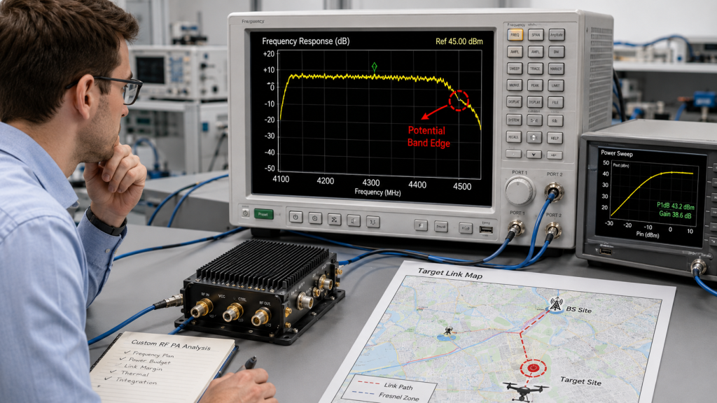
Here’s the engineering point: the project should start from the target link map, not from the supplier’s broadest product label. If your most important link sits near a weak band edge, crosses a split between modules, or requires tighter emission control near civilian systems, custom RF PA frequency bands may reduce system risk.
Check these before assuming standard is enough:
- Target frequencies and hopping behavior
- Required output power across the operating band
- Band-edge power and gain flatness
- Antenna and filter match across the same band
- Allowed emissions near protected services
What the Catalog Does Not Tell You
A catalog can tell you what a wideband RF PA module is designed to cover, but it may not show whether your exact project points are stable under full load. This is why a standard module page such as RF power amplifier modules for C-UAS systems should be treated as a starting point for review, not the final engineering decision.
Key Takeaway: Standard bands are useful when they match real operating conditions, but they are risky when the project assumes coverage without checking the exact frequency, load, and thermal evidence.
| Wrong Assumption | Better Check | Why It Matters |
|---|---|---|
| “The band includes our frequency.” | Verify output at the exact points. | Inclusion does not prove stable power. |
| “Wider is always safer.” | Check antenna and filter match. | Wider coverage can create mismatch risk. |
| “One datasheet point is enough.” | Request full-band sweep data. | Field issues often appear away from center points. |
This table helps you turn a product label into an engineering review instead of a procurement shortcut.
2. How to Avoid Unneeded Custom RF PA Design
A standard RF power amplifier frequency range is the safer choice when it covers your verified threat links with enough output, thermal margin, and acceptance evidence. Customization adds design work, validation time, and batch-control responsibility, so it should not be chosen just because it sounds more advanced.
The practical risk is clear: unnecessary customization can delay a project without improving field performance. If a standard 300–1700 MHz or 300–2700 MHz module already meets the frequency plan, output target, duty cycle, antenna path, and compliance boundary, the lower-risk path may be to use the validated standard option.
A standard band is often enough when:
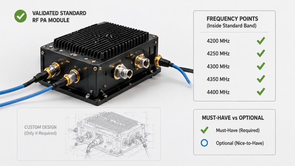
- The key frequencies sit well inside the band
- Required power is stable across test points
- The antenna path is already matched
- The project timeline is tight
- No protected frequency exclusion is required
How to Avoid Over-Customization
The best way to avoid over-customization is to define “must-have” and “nice-to-have” frequencies separately. A C-UAS RF amplifier does not need to be customized for every possible future signal if the current deployment only requires a proven operating window with repeatable test evidence.
Key Takeaway: Use a standard band when it already satisfies the project’s real operating envelope; use customization only when the standard path leaves a measurable risk.
| Selection Condition | Recommended Path | Main Reason |
|---|---|---|
| Frequencies are inside validated range | Use standard band | Lower lead time and lower validation load |
| Critical points are near band edge | Review custom band | Avoid weak output or unstable gain |
| Site has strict exclusion zones | Review custom or filtered path | Reduce collateral interference risk |
This table keeps the decision practical: standard first, custom only when a defined problem justifies it.
3. What Makes Custom RF PA Range Necessary
Custom bands become necessary when the RF power amplifier frequency range must be shaped around project-specific links, site restrictions, or integration limits that standard modules cannot satisfy. The trigger is not “special request”; it is a measurable gap between standard performance and project need.
This is where system integrators should pay attention: custom frequency requirement usually appears after threat mapping, site survey, or early acceptance review. It may come from non-standard drone links, local frequency restrictions, antenna-path constraints, or the need to avoid wasting module count on unnecessary spectrum.
Common triggers include:
- Target links fall between standard module strengths
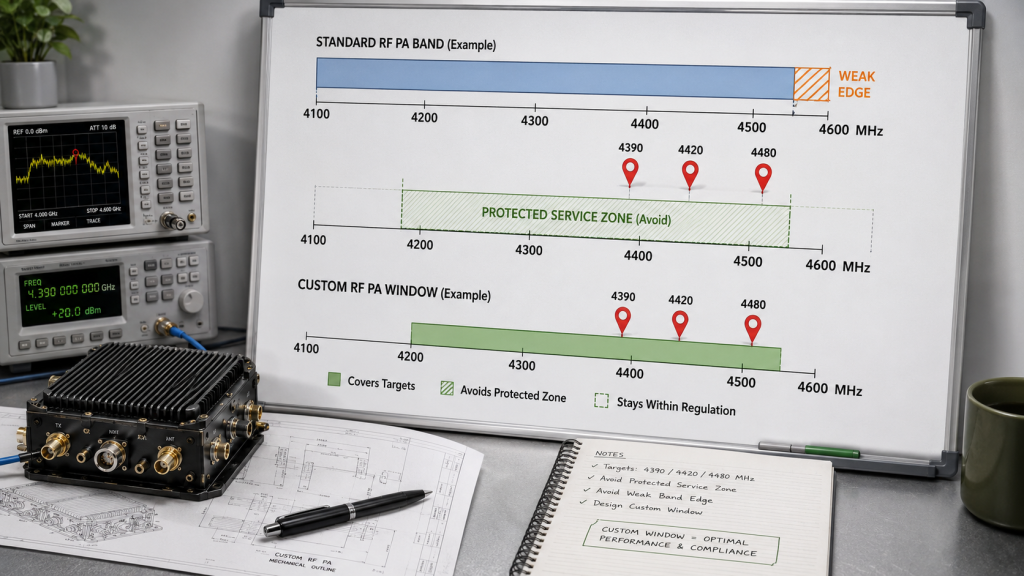
- Required power is not stable at the band edge
- Urban RF environment requires tighter band control
- One platform must reduce module count
- Local regulations limit usable emission windows
- Existing antennas or filters cannot cover the full standard range
Which Trigger Is Strong Enough?
A strong trigger is one that changes system performance or acceptance risk. For example, if an urban rooftop C-UAS project must cover a narrow operational window while avoiding nearby communication services, a custom band can be more useful than installing a broader module that adds thermal load and filtering complexity.
Key Takeaway: A custom band is justified when it solves a defined system problem, not when it only makes the specification look more flexible.
| Trigger | What to Verify | Custom Band Value |
|---|---|---|
| Non-standard target link | Exact frequency and bandwidth | Better coverage of real threat |
| Weak band-edge result | Power and gain at edge points | Lower acceptance risk |
| Dense urban RF site | Exclusion and coexistence needs | More controlled emission behavior |
This table helps you separate real customization triggers from vague requests that do not improve the final system.
4. What Custom RF PA Changes in the RF Chain
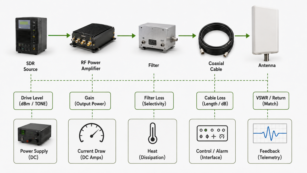
The RF power amplifier frequency range affects the whole system because it changes the behavior of the PA, signal source, antenna, filters, cables, power supply, and protection logic. A frequency decision is never isolated inside the amplifier.
Here’s the field reality: if the PA band changes, the rest of the chain must still support the same operating window. A module that looks correct on the bench can fail integration if the antenna VSWR rises, the filter introduces high insertion loss, or the SDR signal source cannot drive the required band with stable input level.
Review the system impact across:
- Input drive level and gain control
- Antenna VSWR across operating points
- Filter loss and protected-band rejection
- Cable loss at higher frequencies
- Power supply current under full load
- Thermal behavior during sustained operation
Why One Changed Band Can Reopen Integration
Changing the band can reopen mechanical, RF, electrical, and firmware questions. If your project already selected antennas, filters, and control interfaces, the custom RF power amplifier module must be checked against those choices before approval.
Key Takeaway: Frequency customization should be reviewed as a system change, not a module change, because every downstream component must still behave correctly.
| System Area | Possible Effect | Better Review |
|---|---|---|
| Antenna path | Higher mismatch or VSWR | Sweep antenna and PA together |
| Filters | More insertion loss | Check power after filter |
| Power and heat | Higher current and temperature | Test full-load duty cycle |
This table shows why frequency decisions belong in system engineering meetings, not only in supplier quotation emails.
5. Why Are Urban Rooftop C-UAS Sites Different?
Urban rooftop sites make the RF power amplifier frequency range harder to choose because the RF environment is crowded before your system starts transmitting. Dense buildings, cellular infrastructure, Wi-Fi, security radios, broadcast links, and multi-path reflections can all change what “effective coverage” means.
The selection risk appears here: a standard wide band may cover the target signal but still create unnecessary filtering, heat, or coexistence problems. For projects tied to low-altitude security and C-UAS EW environments, the site itself often decides whether the band should be broad, split, narrowed, or customized.
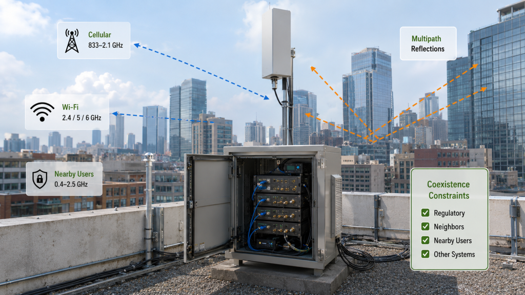
Urban rooftop review should include:
- Nearby critical communication systems
- Roof height and antenna line of sight
- Multi-path and building reflections
- Cabinet cooling limits
- Cable routing length and loss
- Multi-point deployment coordination
Why Venue and Perimeter Sites Raise the Bar
Large venues and city perimeters create dense signal conditions where a brute-force frequency plan can cause more integration work later. A case environment such as urban venue and perimeter security deployment shows why RF planning must consider the surrounding signal environment, not only drone-link coverage.
Key Takeaway: Urban rooftops reward precise frequency planning because uncontrolled broad coverage can increase integration risk even when the module itself is powerful.
| Field Condition | Selection Risk | Better Starting Point |
|---|---|---|
| Dense civilian RF | Collateral interference concern | Define allowed operating window |
| Long roof cable runs | Higher frequency loss | Calculate antenna-end power |
| Small cabinet space | Thermal buildup | Match band to real need |
This table keeps the rooftop decision grounded in site conditions rather than generic frequency assumptions.
6. What Engineering Stress Does Customization Add?
A custom RF power amplifier frequency range adds engineering stress because it can change output power, efficiency, current draw, heat generation, and protection behavior. The band may be tailored to the project, but the physics still need margin.
Here’s the engineering point: a custom band that improves frequency coverage but reduces thermal stability is not a good C-UAS choice. If the module must run for long periods in an outdoor cabinet or rooftop enclosure, the supplier should prove performance under realistic duty cycle, not only short lab bursts.
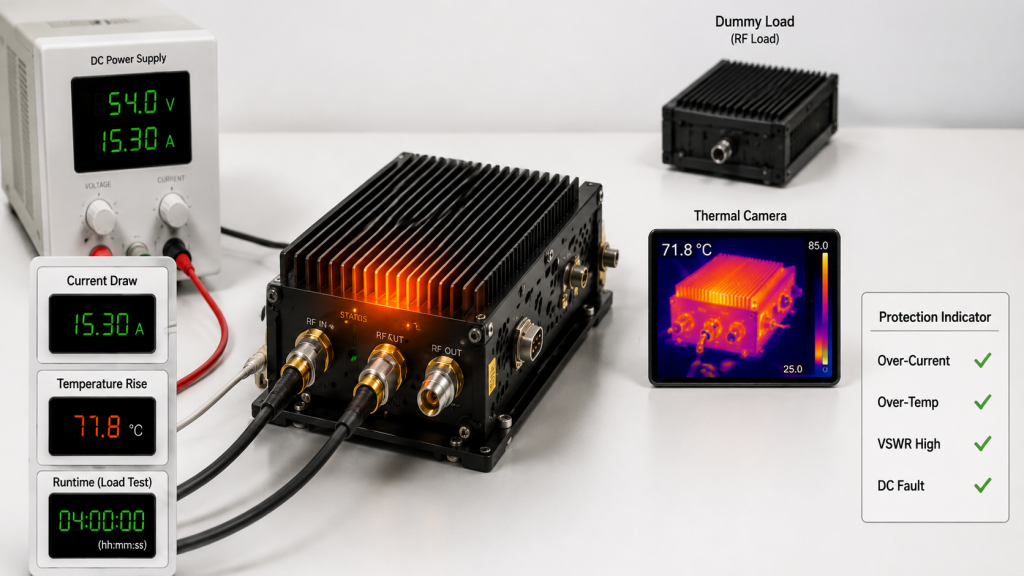
Stress points to check include:
- Output power across all required points
- Gain flatness and current draw
- Heat sink and enclosure thermal path
- Over-temperature protection threshold
- Voltage stability at full load
- Continuous operation behavior
Where Source Factory Review Helps
As a source factory for RF PA modules and C-UAS core components, RF SKYPOWER can support early engineering review by checking frequency range, power target, duty cycle, antenna path, CNC housing, heat dissipation, and protection logic before final module approval. That kind of review matters when a custom band affects both RF performance and mechanical design.
Key Takeaway: Customization is useful only when the supplier can validate the thermal, electrical, and protection consequences of the new operating range.
| Engineering Stress | What Can Go Wrong | Required Evidence |
|---|---|---|
| Wider operating band | Lower efficiency at some points | Full-band power and current data |
| Higher duty cycle | Thermal throttling | Long-duration load test |
| Tight enclosure | Heat buildup | Thermal rise report |
This table helps you ask whether the custom band is truly field-ready or only laboratory-ready.
7. How Should PA, SDR, Antenna, and Filters Match?
A custom RF power amplifier frequency range should be planned around the whole emission chain, including the PA, SDR source, antenna, filters, cables, and control interface. If one part of the chain cannot support the same window, the custom band becomes a paperwork feature instead of a working system function.
The better check is simple: trace the signal path from waveform generation to antenna output. If your SDR signal source module for C-UAS RF systems supports the target band but the antenna match is weak, or if the antenna is suitable but the filter creates excessive loss, the PA alone cannot fix the problem.
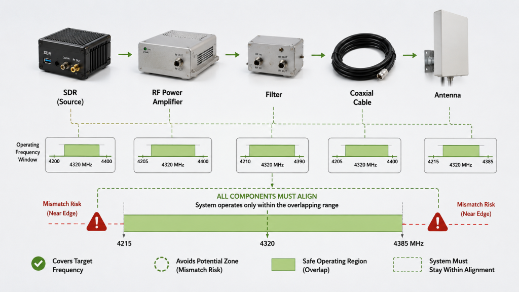
Match these items before approval:
- SDR output level and waveform bandwidth
- PA input drive and gain setting
- Filter passband and rejection targets
- Antenna VSWR and power rating
- Cable loss and connector condition
- Control and alarm feedback
Why Antenna Matching Is Not Optional
The antenna path decides whether PA output becomes useful field energy or reflected power. A page such as PA-to-antenna interface matching is relevant because custom bands can shift VSWR behavior and protection sensitivity.
Key Takeaway: A custom PA band must be validated as part of a complete RF path, because the weakest matched component decides the field result.
| Architecture Option | Trade-Off | Best Use |
|---|---|---|
| One broad PA path | Simpler hardware, higher match burden | Wide coverage with proven antenna path |
| Split custom bands | More modules, better control | Dense RF or protected frequency sites |
| Narrow custom band | Efficient and controlled | Known threat-link projects |
This table helps you choose architecture based on RF path behavior, not just amplifier availability.
8. What Evidence Proves a Custom RF PA Range
You should accept a custom RF power amplifier frequency range only when the supplier proves stable output, thermal behavior, and protection response across the exact band you will use. A single center-frequency screenshot is weak evidence.
This is where acceptance risk often hides. RF PA band edge performance may look acceptable in a short test, then drift under full load, higher ambient temperature, or antenna mismatch. For wideband choices such as 300–1700MHz wideband RF PA modules or 300–2700MHz wideband RF core, the same logic applies: validate the full required range, not only the attractive headline band.
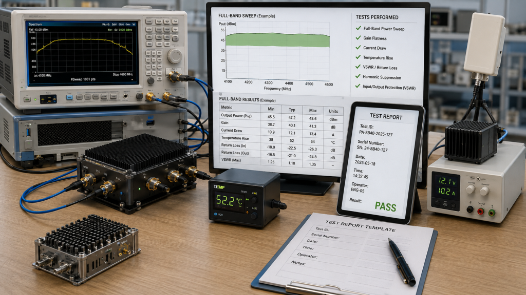
Ask for evidence such as:
- Full-band power sweep
- Gain flatness report
- Input and output match data
- Current draw at key points
- Temperature rise under load
- VSWR, voltage, and temperature protection behavior
- Serial-number-linked test report
What Makes Evidence Repeatable?
Repeatable evidence includes test conditions, load setup, input drive, voltage, ambient temperature, measurement equipment, and the exact frequency points. Without those details, your team cannot reproduce the result during incoming inspection or final system acceptance.
Key Takeaway: Test evidence should let your team repeat the supplier’s claim, because repeatability is what protects procurement, integration, and batch acceptance.
| Weak Evidence | Better Evidence | Why It Matters |
|---|---|---|
| One center-frequency result | Full-band sweep | Shows edge and mid-band behavior |
| Unlabeled power screenshot | Condition-based report | Allows repeat testing |
| No protection test | VSWR and thermal response data | Reduces field failure risk |
This table helps you reject attractive but incomplete proof before it becomes an acceptance problem.
9. How to Specify Custom RF PA Range in RFQs
Before requesting quotation, describe the RF power amplifier frequency range as a complete operating condition, not only a start and stop frequency. A useful RFQ tells the supplier what the module must survive, match, and prove.
Here’s the practical risk: if your RFQ only says “custom 900–1500 MHz PA,” the supplier may quote hardware that meets the number but misses the duty cycle, thermal path, control interface, or test standard. A strong RFQ reduces back-and-forth and prevents late-stage redesign.
Include these items:
- Target frequency range and critical points
- Required output power across band
- Input power and gain requirement
- Duty cycle and runtime
- Operating voltage and current limit
- Antenna/load condition
- Cooling method and enclosure limits
- Control interface and alarm signals
- Protection requirements
- Test report format
Which Details Prevent Wrong Quotes?
The details that prevent wrong quotes are the ones that change design work. Frequency, power, duty cycle, thermal environment, and antenna condition decide whether the supplier quotes a standard module, adjusted module, or new custom RF power amplifier module.
Key Takeaway: A precise RFQ helps the supplier design against your real system instead of guessing from a frequency number.
| RFQ Item | Why It Matters | Example Review Question |
|---|---|---|
| Duty cycle | Defines heat stress | Is this CW, pulsed, or intermittent? |
| Antenna/load condition | Affects VSWR risk | What mismatch must the PA survive? |
| Test report format | Supports acceptance | Can the result be repeated by serial number? |
This table turns the RFQ into an engineering document rather than a price request.
10. How Do You Decide Between Standard and Custom Bands?
You should choose custom bands when the RF power amplifier frequency range required by the project cannot be met safely by a standard module with verified power, thermal, matching, and protection evidence. If the standard path meets those checks, custom work may not be worth the time.
The final decision should be made by risk, not preference. Standard bands reduce schedule and validation burden; custom bands reduce mismatch when the project has special frequency, site, or architecture needs.
Use this decision sequence:
- Map the real threat links
- Check standard module coverage
- Verify band-edge performance
- Review antenna and filter match
- Confirm thermal and power margin
- Request repeatable test evidence
- Compare lead time and batch risk
- Decide standard, adjusted, or custom path
What Is the Final Engineering Rule?
The final rule is to customize only when the customization removes a bigger risk than it creates. If it improves coverage but creates untested thermal, antenna, or batch-consistency risk, the project has only moved the problem to a later stage.
Key Takeaway: The right band is the one your system can verify, integrate, and maintain across the deployment life cycle.
| Selection Condition | Recommended Path | Decision Logic |
|---|---|---|
| Standard band passes all checks | Use standard module | Fastest validated path |
| Standard band has weak edge points | Adjust or customize | Reduce acceptance risk |
| Site requires tight RF control | Custom band review | Match system to field limits |
This table gives engineering and procurement teams a shared decision frame before committing budget or schedule.
FAQ
How do I know if my C-UAS RF PA needs a custom band?
You need a custom band if a standard module cannot prove stable performance across your required frequency points. Check threat links, band-edge output, antenna match, thermal margin, and acceptance evidence before deciding.
What should I check before asking for a custom RF PA quote?
Check frequency range, output power, duty cycle, antenna/load condition, cooling method, operating voltage, control interface, and required test report format. These details decide whether the supplier can quote a realistic design.
Can I use one wideband RF PA instead of custom split bands?
Yes, if the wideband module meets output, gain flatness, antenna match, thermal, and protection requirements across the full operating range. Split or custom bands are better when control, efficiency, or exclusion zones matter more.
When should I choose a standard RF PA module?
Choose a standard module when your critical frequencies sit inside a validated range and the supplier can provide repeatable test data under your operating conditions. Standard is often the lowest-risk option when it truly fits.
What’s the best evidence for custom frequency acceptance?
The best evidence is a repeatable full-band test report tied to clear conditions and serial numbers. It should include power sweep, gain flatness, current draw, temperature rise, and protection behavior.
Conclusion
Custom RF PA frequency bands are useful when they solve a verified C-UAS integration problem: weak band-edge performance, non-standard threat links, dense urban RF conditions, protected-frequency restrictions, or system architecture limits. They are not automatically better than standard bands. The better decision comes from mapping the threat links, checking the full RF path, proving thermal and protection behavior, and writing an RFQ that describes real operating conditions.
RF SKYPOWER can help engineering teams review frequency range, power target, duty cycle, antenna path, thermal structure, protection logic, and repeatable test evidence before module approval. To review your RF module requirements for a C-UAS project, discuss your project with our engineering team.
Field-ready C-UAS systems are built on verified RF decisions, not catalog shortcuts.