


RF PA Frequency Range should not be judged only by room-temperature sweep data, especially in temporary event C-UAS deployments. A module may still operate inside its rated frequency range, but temperature can shift its real behavior at different frequency points, changing output power, gain, efficiency, VSWR response, protection margin, and repeatability after the PA reaches hot-state operation.
This matters because temperature does not weaken every part of the band in the same way. A center frequency may remain stable while a band edge, high-frequency point, or project-critical target frequency loses usable margin under heat. In stadiums, concerts, exhibitions, VIP events, and temporary perimeter security projects, direct sunlight, temporary cabinets, long feeder paths, fast installation, and concentrated duty cycles can expose these differences during the most important operating window.
This article explains how temperature shifts RF PA Frequency Range behavior across low, center, high, and band-edge frequency points. It shows what hot-state output, gain flatness, VSWR, alarm status, and reference-point data engineers should request before choosing RF Power Amplifier modules for temporary C-UAS deployment.
1. What Shifts RF PA Frequency Range Behavior
Temperature matters to RF Power Amplifier Frequency Range because it can change output power, gain, efficiency, protection margin, and repeatability differently across the usable band. A datasheet frequency range may remain the same on paper, but the module’s real usable behavior can change after heat builds.
Here’s the engineering point: frequency behavior is not just “can the module amplify this frequency?” It also includes output level, gain stability, current draw, VSWR response, thermal margin, and whether protection logic stays inactive during the required duty cycle.
What changes when the module gets hot?
As temperature rises, the PA device operating point, matching behavior, internal loss, current draw, and protection margin can shift. The module may still operate at the stated frequency, but with less output margin or less repeatability.
Engineers should check:
- Output power by frequency
- Gain by frequency
- Current draw under load
- Module temperature
- VSWR or reflected power
- Protection and alarm status
- Cold-state versus hot-state repeatability
For RF Power Amplifier modules, this is why frequency range should be reviewed together with output, duty cycle, cooling, antenna load, and test evidence.
Key Takeaway: Temperature does not usually “move” the rated band label; it changes how much usable performance remains at each frequency point.
| Wrong Assumption | Better Check |
|---|---|
| The rated band is fixed, so behavior is fixed | Check hot-state output by frequency |
| One room-temperature sweep is enough | Compare room and hot-state data |
| Temperature only reduces total power | Review gain, current, VSWR, and alarms |
| Center-frequency data proves the full band | Test low, center, high, and target points |
This table helps engineers treat temperature as a frequency-behavior variable, not only as a cooling concern.
2. How to Compare RF PA Frequency Range Under Heat
Hot conditions can change RF Power Amplifier Frequency Range behavior differently across low, mid, and high bands because each part of the RF path has different matching, loss, efficiency, and thermal pressure. A low-band result should not be used to approve a high-band target, and a center-frequency result should not approve the whole band.
The practical risk is clear: a module may pass one attractive point while a project-critical point weakens after heat builds. In temporary event security, that difference may only appear during the busiest operating window.
What should engineers compare across bands?
Low, mid, and high bands should be tested under the same voltage, load, duty cycle, cooling condition, and measurement reference point. If those conditions change between tests, the comparison becomes unclear.
Useful checks include:
- Low-band output and current
- Mid-band output and thermal behavior
- High-band output after feeder loss
- Band-edge margin
- Target-frequency hot-state data
- Antenna-port or PA-port reference point
A broad mid-band PA path should be reviewed by low, center, high, target-frequency, and hot-state behavior before temporary C-UAS deployment. A high-band PA path also needs thermal and RF-path review because module heat, feeder loss, connector condition, and antenna match can combine.
Key Takeaway: Hot-state frequency behavior should be compared point by point, not assumed from one favorable test point.
| Band Area | What Can Shift Under Heat | Better Evidence |
|---|---|---|
| Low band | Matching and repeatability | Hot-state target data |
| Mid band | Current and gain behavior | Same-condition sweep |
| High band | Feeder loss and output margin | Antenna-path evidence |
| Band edge | Less design margin | Edge hot-state test |
| Target point | Project-specific output | Frequency-point report |
This table helps prevent one good frequency result from being treated as full-band proof.
3. What Heat Reveals at RF PA Frequency Range Edges
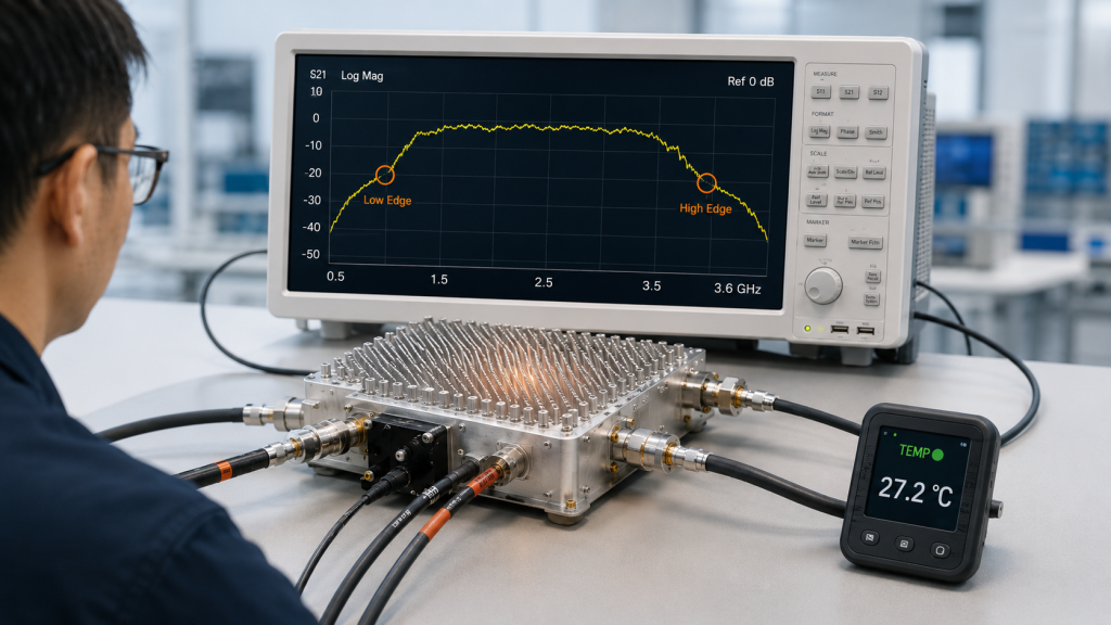
Band edges are more sensitive within RF Power Amplifier Frequency Range because they often have less output, gain, matching, and thermal margin than center-frequency points. Temperature stress can expose weaknesses that remain hidden during room-temperature center-point testing.
This is not the same as saying every band edge will fail. The better statement is that edge points deserve separate evidence, especially when the project depends on them.
What makes edge points vulnerable?
At the low and high ends of a rated band, the amplifier may be closer to the design limits of matching networks, device behavior, efficiency, and stability. When heat rises, that smaller margin can become more visible.
Band-edge risk may appear as:
- Lower output than center points
- Higher current for the same output
- Faster temperature rise
- Greater VSWR sensitivity
- Earlier protection response
- Less repeatable hot-state behavior
Band-edge output should be checked under temperature stress because low and high frequency edges may lose margin faster than center-frequency points.
Why does this matter in temporary events?
Temporary event deployments often use broad coverage expectations with limited site-testing time. If a key frequency is near the edge of a PA range, engineers should not wait until installation day to learn whether hot-state operation still has enough margin.
Key Takeaway: Band edges need hot-state evidence because temperature can reduce already limited design margin.
| Edge Condition | Selection Risk | Better Check |
|---|---|---|
| Key target near low edge | Weak hot-state output | Low-edge hot test |
| Key target near high edge | Higher loss and heat | High-edge hot test |
| Center point looks strong | Edge risk hidden | Low/center/high comparison |
| VSWR margin is narrow | Protection may trigger | Reflected-power data |
| Duty cycle is long | Edge weakness grows | Hot-state duration test |
This table helps engineers separate true full-band capability from center-frequency confidence.
4. How to Read RF PA Frequency Range Gain Changes
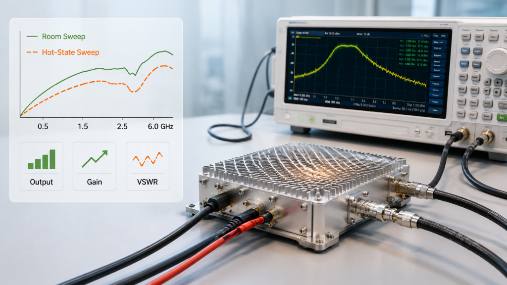
Temperature affects RF Power Amplifier Frequency Range by changing gain flatness across a wideband RF PA module, so the hot-state gain curve may not match the room-temperature curve. That matters because gain variation can turn into uneven output across C-UAS target bands.
This is where system integrators should pay attention: a room-temperature sweep may look acceptable, but after warm-up, some frequency points may drop faster than others. That creates an across-band consistency problem, not just a thermal problem.
What should hot-state gain flatness show?
Gain flatness should be reviewed as a curve across the operating band, not as one number at one point. Engineers should compare room-temperature and hot-state sweep data using the same drive level, supply voltage, load, and reference point.
Useful evidence includes:
- Room-temperature gain sweep
- Hot-state gain sweep
- Output power at the same points
- Current and module temperature
- VSWR or reflected-power status
- Target-frequency pass/fail boundary
Gain flatness testing becomes more useful when engineers compare room-temperature and hot-state sweep data across the same RF Power Amplifier frequency range.
Why is gain not enough by itself?
Gain flatness helps explain frequency behavior, but it should not be used alone. Final usable output also depends on drive, voltage, efficiency, thermal condition, antenna path, and protection logic.
Key Takeaway: Hot-state gain flatness helps reveal whether a wideband module remains predictable across the band after heat builds.
| Weak Evidence | Better Evidence |
|---|---|
| One gain value | Full sweep by frequency |
| Room-temperature curve only | Room and hot-state curves |
| Gain without output power | Gain plus output and current |
| Sweep without temperature | Sweep with thermal state |
| No target-point boundary | Project-specific pass/fail points |
This table helps engineers read gain flatness as part of a temperature-aware frequency review.
5. Why Can Temporary Event Deployments Expose Temperature-Related Frequency Weakness?
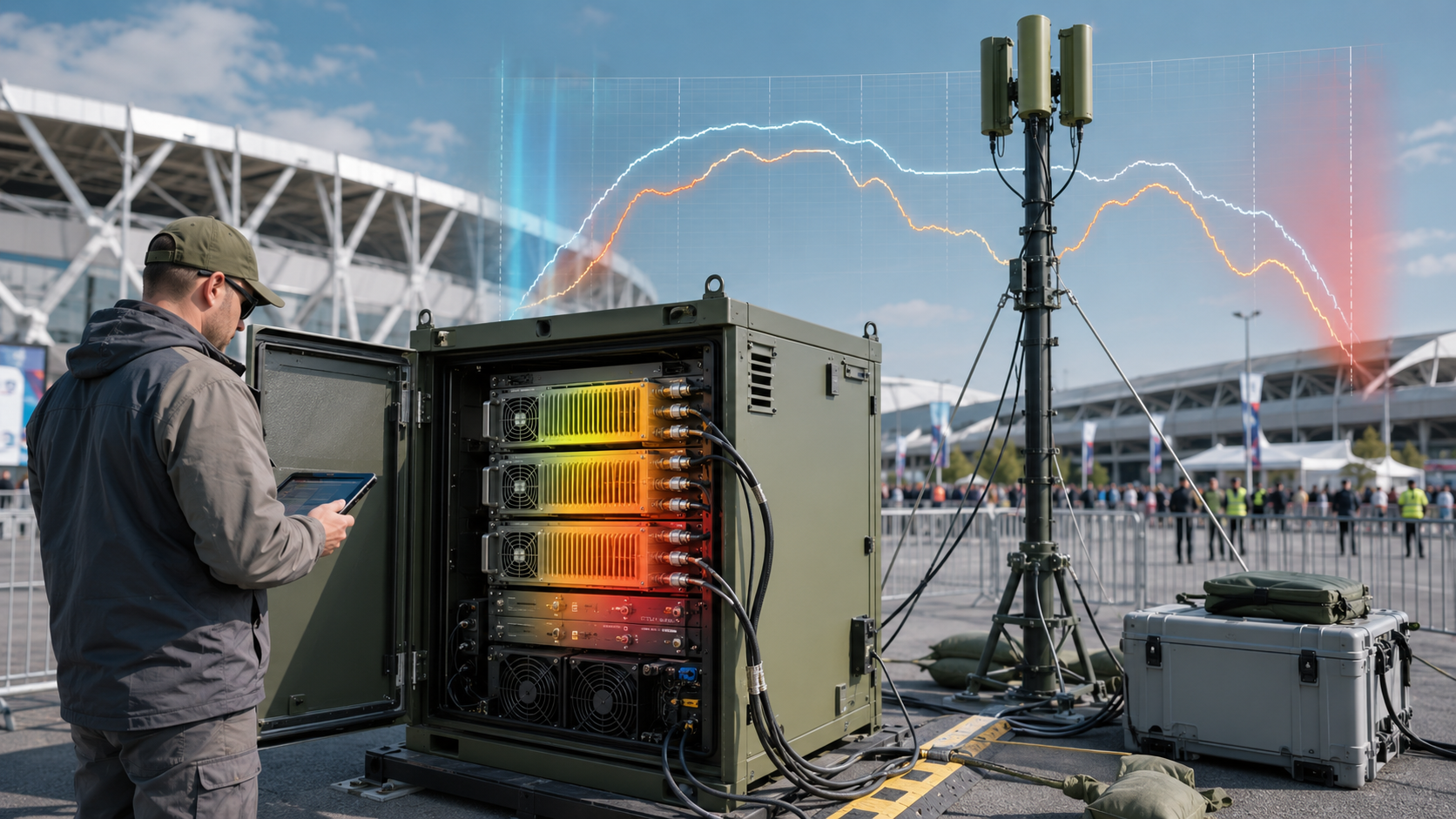
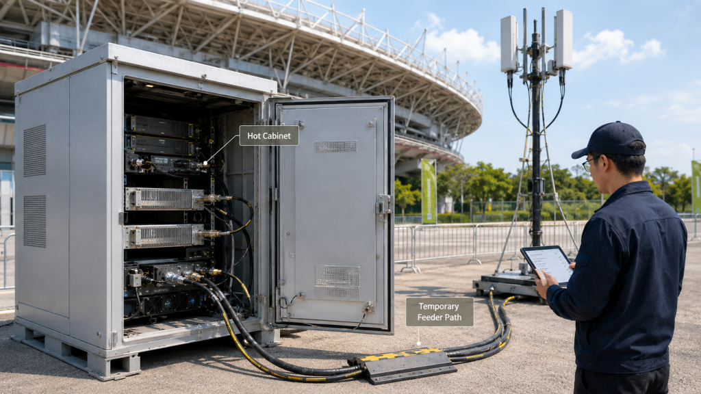
Temporary event deployments can expose RF Power Amplifier Frequency Range weaknesses because fast setup, temporary cabinets, outdoor heat, long feeder paths, and concentrated duty cycles leave little time to discover hot-state band behavior on site. A system that looks acceptable during a short indoor check may behave differently in a temporary perimeter environment.
Here’s the field reality: event security is temporary, but the RF demand can be severe. Stadiums, concerts, exhibitions, VIP visits, and diplomatic events often combine dense communications, outdoor heat, rapid installation, and high operational pressure.
What event conditions create risk?
Temporary event C-UAS projects may face:
- Direct sunlight on cabinets
- Short setup windows
- Temporary power
- Temporary antenna masts
- Long or improvised feeder paths
- Repeated connector handling
- Dense media and security communications
- Long standby followed by high duty cycle
- Limited time for retesting
A venue perimeter case shows why temporary C-UAS deployments need controlled RF behavior, stable power, and test evidence before high-density event operations begin.
The most important frequency point may not weaken during setup. It may weaken during the peak event window, when cabinet temperature, duty cycle, operator demand, and RF path stress rise together.
Why is daytime heat different from a short test?
A short indoor test proves a moment. A hot outdoor cabinet tests sustained margin. If a critical frequency weakens only after heat accumulation, the team may not have time to redesign the cabinet, change the antenna path, or request different PA grouping.
Key Takeaway: Temporary deployment increases the value of pre-event hot-state frequency evidence.
| Event Condition | Frequency-Behavior Risk | Better Preparation |
|---|---|---|
| Fast installation | Little retest time | Predefined test report |
| Outdoor cabinet | Heat accumulation | Hot-state data |
| Long feeder path | Higher installed loss | Antenna-path review |
| Dense RF environment | Less room for error | Controlled RF plan |
| High-duty event window | Thermal drift appears late | Duty-cycle testing |
This table connects temporary event constraints with the frequency evidence engineers should request before deployment.
6. How Do VSWR and Antenna Load Behave Differently as Temperature Changes?
VSWR and antenna load can change the usable RF Power Amplifier Frequency Range because output drops may come from reflected power, antenna mismatch, connector condition, feeder loss, or PA protection status—not only from PA heat. Temperature can make these effects more visible, especially in temporary installations.
The better check is simple: if output drops at one frequency under heat, do not assume the PA module alone is the cause. Check the load path and protection feedback at the same time.
What should be checked in the RF path?
Temporary event sites often involve repeated installation and removal. Cable routing, connector torque, antenna placement, and weather exposure may not match a controlled factory bench.
Engineers should review:
- Antenna match by frequency
- Feeder length and loss
- Connector and adapter count
- Cable bend radius
- Reflected power trend
- VSWR alarm status
- Module temperature
- Output reference point
In Low-Altitude Security & C-UAS EW systems, installed RF behavior should be judged as a chain: PA module, cable, antenna, load, protection feedback, and control logic.
Why does protection status matter?
VSWR protection is a safety mechanism. It prevents damage, but it does not make a weak antenna path into a stable system. If protection triggers, the system may reduce output before the operator understands why a band weakened.
Key Takeaway: Temperature-related output drops should be checked together with antenna load, reflected power, and protection status.
| Symptom | Possible Cause | First Check |
|---|---|---|
| Output drops at one band | Antenna mismatch | VSWR by frequency |
| Output drops after heat | Thermal or load drift | Temperature plus reflected power |
| Alarm appears at high band | Connector or feeder issue | RF path inspection |
| PA works on dummy load | Installed path differs | Antenna-port review |
| Protection triggers | Unsafe load condition | VSWR feedback and log |
This table helps teams avoid blaming the PA before checking the full RF path.
7. How to Test RF PA Frequency Range in Hot State
RF Power Amplifier Frequency Range under temperature should be proven by multi-point output, gain, current, temperature, VSWR, protection status, duty-cycle, and reference-point data—not by a single room-temperature sweep. The test does not need to become unrealistic, but it must match the project risk.
This is where RFQ and acceptance become practical. If the project depends on certain frequencies during hot outdoor operation, those points should appear in the test request.
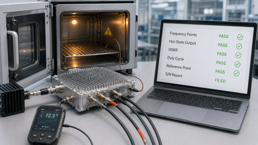
What should the report include?
A useful temperature-aware frequency report should record:
- Tested frequency points
- Output power
- Gain
- Input drive
- DC voltage
- Current
- Module temperature
- Ambient or cabinet temperature
- Duty cycle
- Load condition
- VSWR or reflected power
- Protection status
- Test duration
- Cooling condition
- Output reference point
If the site may face high-temperature operation, engineers should also review hot-state output behavior before trusting room-temperature PA data.
Which frequency points matter most?
The test should include low edge, center, high edge, project target points, known high-loss points, high-heat points, and antenna-path critical points. For temporary events, S/N-linked reports are useful because they help identify whether a field issue is system-wide or unit-specific.
Key Takeaway: Temperature-aware frequency testing should prove the points the project will actually depend on.
| RFQ Test Item | Why It Matters |
|---|---|
| Target frequency points | Matches project need |
| Hot-state output | Shows thermal behavior |
| Current and voltage | Reveals efficiency and load |
| VSWR status | Separates load from PA issues |
| Output reference point | Prevents measurement disputes |
| S/N-linked report | Supports fast field review |
This table helps buyers request evidence that can be used during both procurement and site troubleshooting.
8. What Alarm Data Shows About RF PA Frequency Range
Temperature protection data should be read as part of RF Power Amplifier Frequency Range behavior because a hot PA module may protect itself before the C-UAS system loses coverage silently. Protection is not only a safety feature; it is also a status signal that helps explain frequency-dependent output changes.
Here’s the practical risk: a supplier may say “with over-temperature protection,” but that does not tell the integrator when the alarm occurs, how output changes, whether the control system sees it, or whether the event is tied to a certain frequency point.
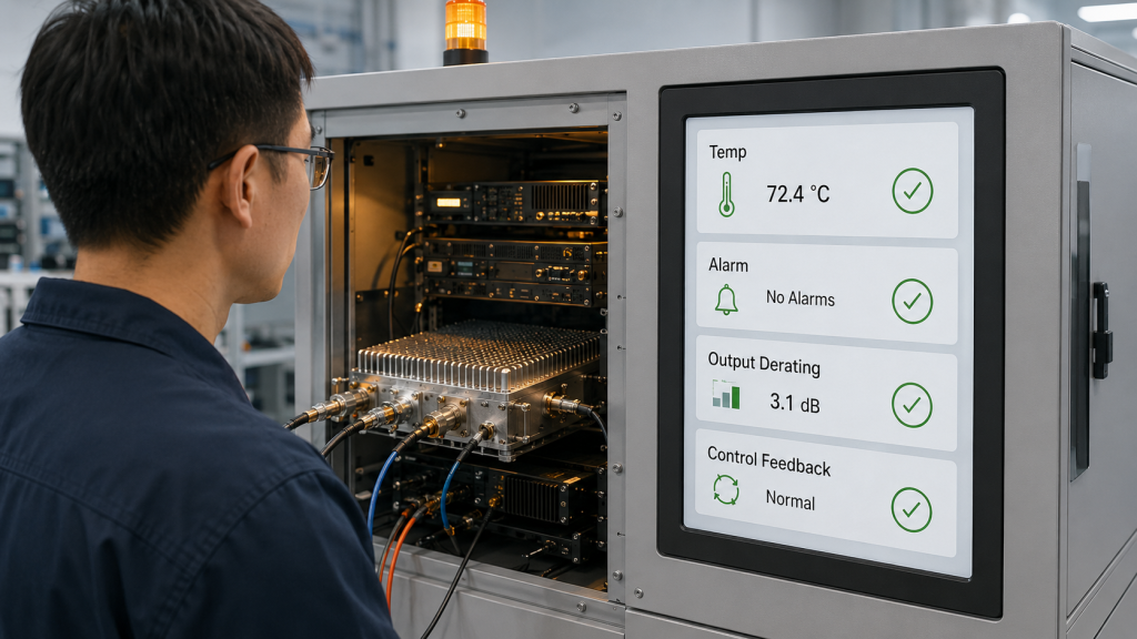
What alarm data should be requested?
Engineers should ask for:
- Temperature alarm threshold
- Shutdown threshold
- Recovery behavior
- Control feedback method
- Frequency point during alarm
- Output level at alarm
- Current and voltage
- Duty cycle
- Test duration
- S/N-linked record
Over-temperature protection confirms that the module can protect itself; it does not prove that the C-UAS system can maintain required band coverage before protection begins. A hot module can pass one short test and still approach a protection limit during a longer event-duty run.
How does alarm data support integration?
Alarm data helps separate four possible causes: thermal overload, antenna mismatch, supply issue, or module-level fault. That makes troubleshooting faster during temporary deployment, where there is little time for slow diagnosis.
If the system interface does not show this state, operators may think the band is active while actual output has already dropped or derated.
Key Takeaway: Protection data becomes useful only when it is tied to frequency point, duty cycle, output, temperature, and control feedback.
| Alarm Detail | Why It Matters |
|---|---|
| Threshold value | Shows protection boundary |
| Frequency point | Identifies band-specific heat |
| Output at alarm | Shows coverage impact |
| Control feedback | Lets operators see status |
| Recovery behavior | Supports event response |
| S/N report | Supports unit-level review |
This table helps engineers turn alarm data into actionable integration information.
9. How Should RFQ Documents Define Temperature-Aware Frequency Range?
RFQ documents should define RF Power Amplifier Frequency Range with target points, hot-state output, duty cycle, cabinet temperature, cooling method, antenna path, protection feedback, and repeatable test evidence. A request that only states frequency range and wattage is too weak for temporary event security.
The selection risk appears here: “Need a wideband 100W RF PA module” may lead to a room-temperature, short-duration, PA-port quotation. That does not prove the module will remain usable at the project’s critical points in a hot temporary cabinet.
What should the RFQ include?
A better RFQ should include:
- Target frequency range
- Target frequency points
- Expected ambient temperature
- Expected cabinet temperature
- Duty cycle
- Operating duration
- Cooling method
- Output reference point
- Feeder length
- Load condition
- VSWR requirement
- Protection feedback
- Hot-state output requirement
- Test report format
- S/N-linked report requirement
- Temporary deployment condition
Not every project needs extreme full environmental testing. But every project should define the temperature, duty cycle, frequency points, and reference plane that matter most.
How should buyers judge supplier response?
If a supplier cannot explain the hot-state frequency behavior, the buyer should treat the rated range as a shortlist, not approval. The useful answer is not only “yes, it covers the band.” It is “here is how the target points behave under the requested thermal and RF conditions.”
Key Takeaway: A temperature-aware RFQ turns a frequency label into testable operating requirements.
| Weak RFQ Line | Better RFQ Requirement |
|---|---|
| “Wideband 100W module” | Target points plus hot-state output |
| “Outdoor use” | Expected cabinet temperature |
| “High duty” | Duty cycle and duration |
| “Stable output” | Pass/fail output by frequency |
| “With protection” | Alarm threshold and feedback |
| “Test report needed” | S/N-linked report format |
This table helps procurement teams define what they actually need before approving the module.
10. How Can Source-Factory Review Reduce Temperature-Related Band Risk?
Source-factory review can reduce RF Power Amplifier Frequency Range risk by connecting frequency points, output target, thermal path, cooling method, protection logic, antenna load, and hot-state test evidence before temporary C-UAS deployment. The goal is not to replace site validation. The goal is to prevent avoidable surprises after hardware is purchased.
This is the final decision point: temperature-related band weakness is rarely solved by choosing a bigger wattage number alone. It needs a combined review of RF behavior, thermal path, load condition, power supply, control feedback, and acceptance evidence.
What can be reviewed before module approval?
As a source factory for RF Power Amplifier modules and C-UAS core components, RF SKYPOWER can help integrators review target frequency points, hot-state output, cabinet temperature, duty cycle, antenna path, protection logic, and repeatable test evidence before temporary event deployment.
A practical review may include:
- Frequency-point output
- Band-edge margin
- Hot-state gain behavior
- Current and thermal pressure
- VSWR and reflected power
- Cooling path
- 28V supply condition
- Control feedback
- S/N-linked report needs
How should product options be discussed?
If the project needs broad mid-band coverage, a mid-band wideband path should be reviewed with temperature-aware frequency evidence. If the project needs high-band coverage, a high-band PA path should be reviewed with feeder, connector, antenna, and hot-state data. If the project has narrower targets, custom or segmented paths may be more practical than assuming one wide label solves every condition.
Key Takeaway: Source-factory review is useful when it turns temperature-sensitive frequency behavior into measurable product and test requirements.
| Review Area | Why It Reduces Risk |
|---|---|
| Target frequency points | Avoids testing the wrong band |
| Hot-state output | Shows usable margin |
| Cooling path | Connects thermal design to RF behavior |
| VSWR feedback | Separates load issues from PA issues |
| Protection logic | Prevents silent coverage loss |
| S/N reports | Supports fast field diagnostics |
This table gives integrators a practical framework for discussing temperature-related RF PA risk before shipment.
FAQ
Can room-temperature data prove RF PA frequency performance?
No. Room-temperature data can shortlist a module, but it cannot prove hot-state behavior. Engineers should request target-frequency output, gain, current, temperature, VSWR, and protection status under the expected operating conditions.
What should I check before using a wideband RF PA at an event?
Check low, center, high, edge, and project target frequency points under realistic duty cycle, cooling, load, and temperature conditions. Wideband coverage should be proven by usable hot-state behavior, not only by a rated frequency label.
How do I know if output drop is caused by heat or VSWR?
Compare output, module temperature, current, VSWR, reflected power, and alarm status at the same frequency point. If output drops while reflected power rises, the antenna path may be involved; if temperature rises toward alarm limits, thermal protection may be involved.
When should RFQ documents include hot-state frequency data?
They should include it whenever the project involves outdoor cabinets, temporary deployment, high duty cycle, wideband operation, high-band paths, or critical target frequencies near band edges. These conditions make room-temperature data less reliable.
Does temperature protection guarantee stable RF output?
No. Temperature protection helps prevent damage, but it does not guarantee stable output. Engineers should still check when alarms trigger, whether output derates, how recovery works, and whether the control system can read the protection state.
Conclusion
Temperature does not simply reduce RF PA output in one uniform way. It can change gain, output power, efficiency, VSWR behavior, protection margin, and repeatability differently across low, center, high, and band-edge frequency points. That is why RF Power Amplifier Frequency Range should be judged with temperature-aware test evidence, not only with room-temperature datasheet data.
For temporary event C-UAS deployments, this matters because fast installation, temporary cabinets, direct sunlight, long feeder paths, dense communications, and concentrated duty cycles can expose weak points at the worst time. Engineers should verify hot-state behavior at target frequencies before trusting rated frequency range, especially when the project depends on wideband modules or high-band paths.
As a source factory for RF Power Amplifier modules and C-UAS core components, RF SKYPOWER can help review target frequency points, hot-state output, duty cycle, cabinet temperature, antenna path, VSWR feedback, protection logic, and S/N-linked test evidence before final module selection. If your team is preparing a temporary event C-UAS deployment, contact us today to review your frequency range and thermal evidence before field changes become expensive.
Field-ready C-UAS RF performance starts with tested frequency behavior under real temperature, not room-temperature assumptions.