


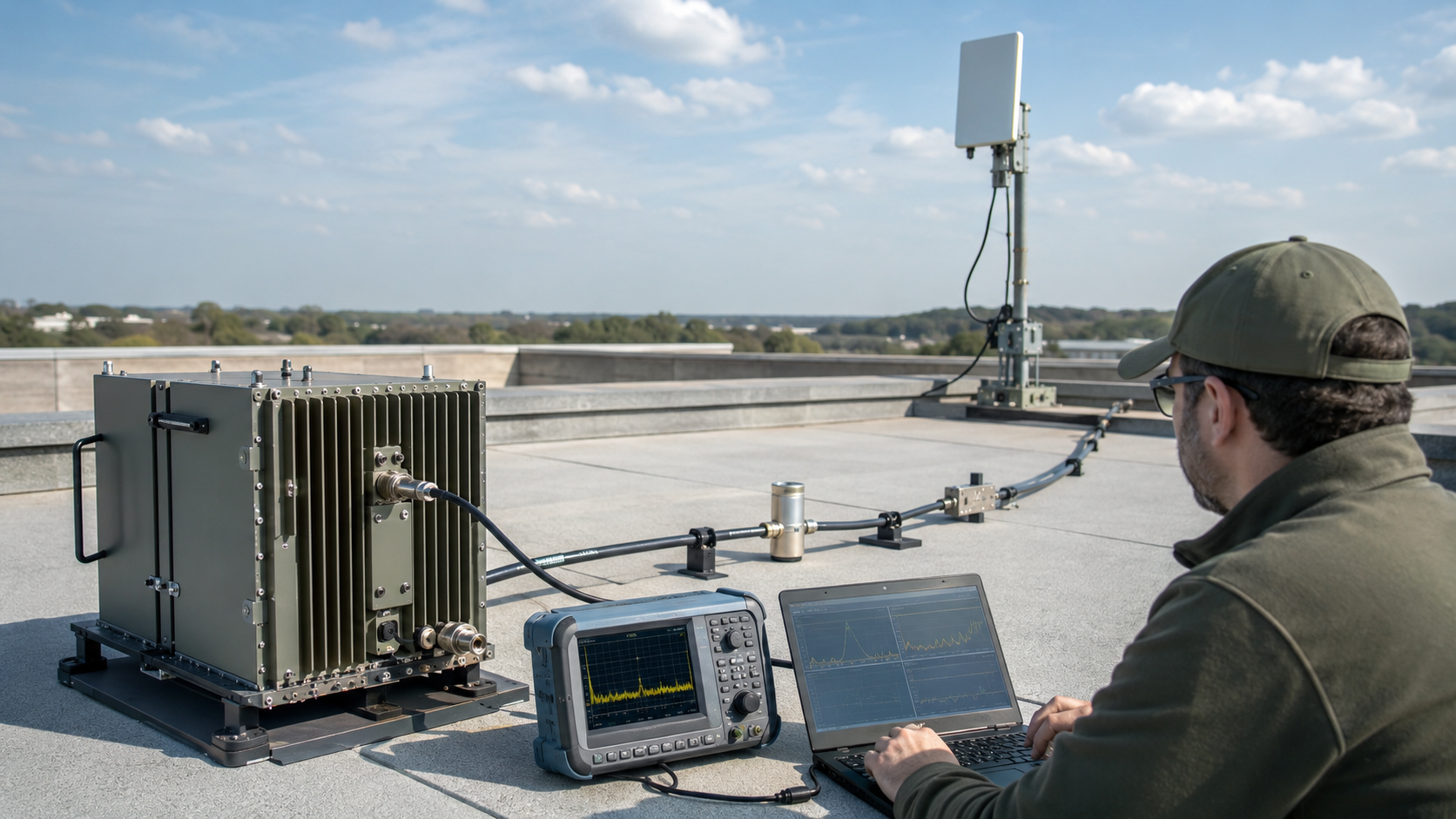
Frequency-Specific VSWR problems appear when an RF PA system is well matched at one operating point but shows higher reflected power, output reduction, alarms, or protection response at another. A module may pass dummy-load testing and perform normally at a center frequency, yet still expose VSWR risk after the real antenna, feeder path, connector stack, lightning protection, and fixed-site installation are included.
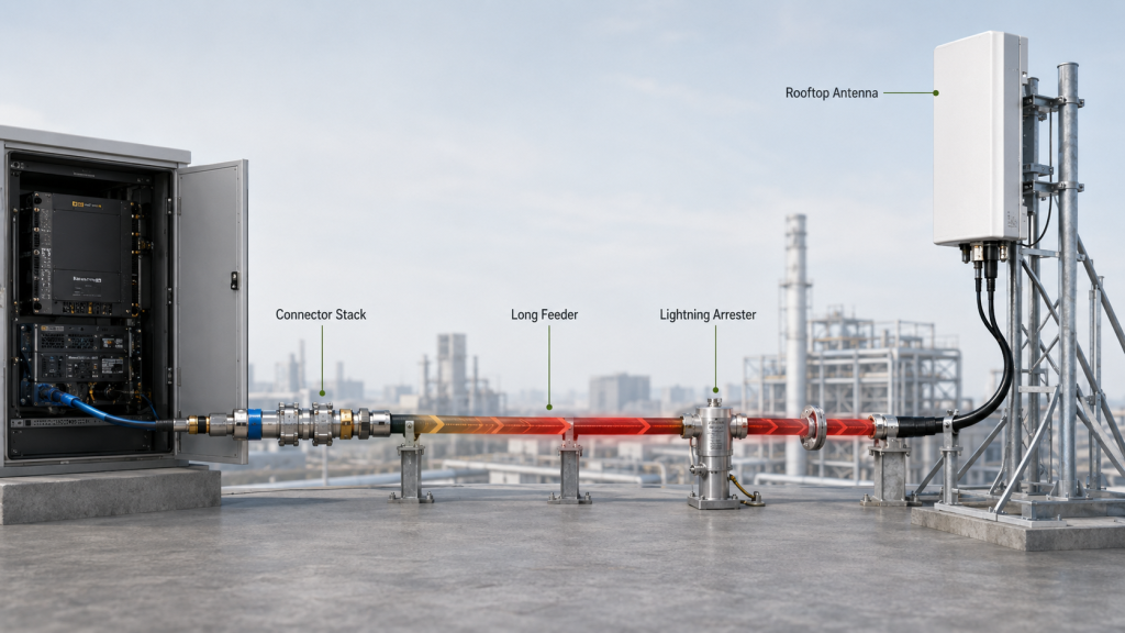
This matters in fixed-site C-UAS and low-altitude security systems because the RF path is rarely a simple PA-to-load connection. Long feeder cables, outdoor antennas, cabinet feedthroughs, waterproof connectors, lightning arresters, filters, switches, and nearby metal structures can all change impedance behavior differently across frequency points. As a result, one target frequency may remain stable while another becomes a reflected-power or acceptance problem.
This article explains why Frequency-Specific VSWR problems appear, how antennas, feeders, connectors, band edges, power level, and reference-point differences create frequency-dependent risk, and what test evidence engineers should request before approving RF Power Amplifier modules for fixed-site C-UAS deployment.
1. What Frequency-Specific VSWR Means in RF PA Systems
Frequency-specific VSWR means RF Power Amplifier Frequency Range cannot be judged as one flat, uniform condition across the whole band. An RF path may be well matched at one frequency but poorly matched at another, so reflected power must be checked across the actual operating points, not only at one test frequency.
This is especially important in fixed-site C-UAS systems. A site may use the same RF PA, cabinet, feeder, and antenna path, yet show normal VSWR at one target frequency and higher reflected power at another. That does not always mean the PA is defective. It may mean the full RF path behaves differently at different frequencies.
Why is VSWR not one fixed system value?
VSWR reflects how well RF energy transfers from the PA output to the load. That load is not only the antenna. It includes cable, connectors, adapters, filters, switches, lightning protection, bulkhead ports, and the installed antenna environment.
Each part of that path has frequency-dependent impedance, loss, and phase behavior. As frequency changes, the load seen by the PA can also change.
In Low-Altitude Security & C-UAS EW systems, RF behavior should be reviewed as a chain: PA module, feeder path, antenna load, reflected power, protection feedback, and control logic.
Why does this affect frequency range selection?
A datasheet may say a PA module covers a certain range, but the installed system may not remain equally safe at every point. The practical question is not only “does the module cover this frequency?” It is also “does the real antenna path remain matched enough at this frequency under operating power?”
Key Takeaway: VSWR is frequency-dependent, not only hardware-dependent.
| Engineering Assumption | More Accurate View |
|---|---|
| VSWR is one system value | VSWR changes by frequency |
| Dummy load behavior proves the full system | Dummy load proves only standard-load behavior |
| One good frequency is enough | Target points and edges must be checked |
| VSWR alarm means PA failure | It may be antenna, feeder, filter, or path behavior |
| Rated frequency range equals usable range | Real load behavior defines usable points |
This table helps engineers treat VSWR as a frequency-specific behavior instead of a single pass/fail label.
2. How to Check Frequency-Specific VSWR After Dummy Loads
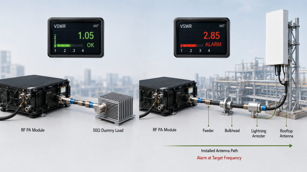
A dummy load test can prove RF PA behavior under a clean 50Ω load, but it can hide frequency-specific VSWR problems that only appear after the module is connected to the real antenna and feeder path. This is why RF Power Amplifier Frequency Range should be verified in both standard-load and installed-load conditions.
Dummy load testing is necessary. It helps confirm that the PA module can produce output, remain stable, draw expected current, and operate without immediate reflected-power alarms under a controlled reference load. But it does not reproduce the full installed RF path.
What does a dummy load test prove?
A good dummy load test can prove:
- Basic PA output behavior
- Standard 50Ω load stability
- Initial protection behavior
- Current and voltage response
- Thermal behavior under controlled load
- Factory repeatability
This test is valuable because it helps separate module-level behavior from system-level load problems.
What does it not prove?
A dummy load does not prove that the antenna, feeder length, lightning protection, connector stack, mounting structure, or outdoor RF path will remain well matched across every operating frequency. Real antennas and installed paths are not perfect 50Ω loads across all frequencies.
If the PA works normally on a dummy load but alarms on the installed antenna path, engineers should not immediately blame the PA. They should compare the PA-port result with antenna-path reflected-power behavior.
Module selection should connect rated frequency coverage with real antenna-load behavior, feeder-path VSWR, reflected-power limits, and target-frequency acceptance.
Key Takeaway: Dummy load testing proves the module under a clean reference load, not the installed antenna path.
| Test Type | What It Proves | What It Cannot Prove |
|---|---|---|
| Dummy load test | PA behavior under clean 50Ω load | Installed antenna VSWR |
| PA-port measurement | Module-side output condition | Feeder and antenna effects |
| Antenna-port test | Installed path behavior | Pure PA-only condition |
| Single-frequency test | One target point | Full-band safety |
| High-power path test | Real reflected-power stress | Long-term field aging |
This table shows why dummy load and installed-path testing should complement each other, not replace each other.
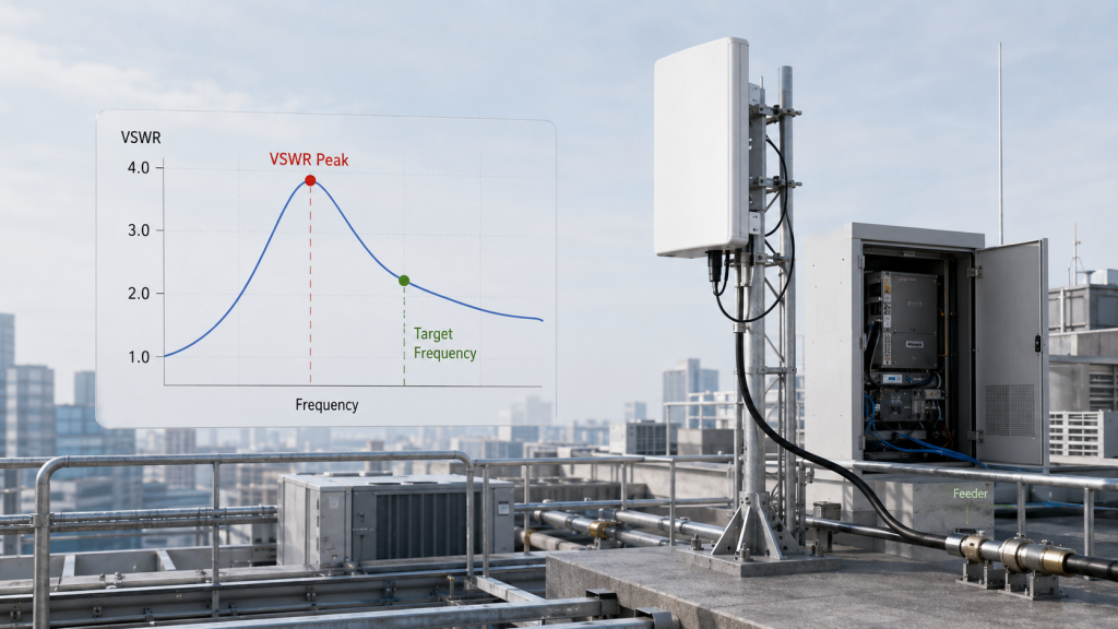
3. How Do Antennas Create VSWR Peaks at Certain Frequencies?
Antennas create VSWR peaks at certain frequencies because their real impedance, bandwidth, mounting environment, and nearby structures do not remain perfectly matched across every point in the RF Power Amplifier Frequency Range. A rated antenna band does not mean every frequency inside that band behaves equally.
This matters for both wideband and narrowband C-UAS systems. A target frequency may fall inside the antenna’s rated range but still sit near a matching dip, transition area, or installation-sensitive point.
Why does antenna matching vary across the band?
An antenna is a frequency-dependent device. Its impedance, radiation behavior, and match quality vary across its operating range. Wideband antennas are especially useful when a system must cover many bands, but they still involve design trade-offs.
A wideband antenna may perform well across most of the required range while showing higher VSWR at certain points. This does not automatically mean the antenna is poor. It means engineers need target-frequency evidence.
High power wideband antenna selection should be checked with the RF PA target frequency points because antenna match and VSWR behavior can vary across the same rated band.
How does installation change antenna VSWR?
Fixed-site antennas are often installed on rooftops, towers, poles, perimeter fences, or building structures. Nearby metal, lightning protection, other antennas, brackets, and cable routing can change installed VSWR compared with lab data.
A frequency that looked acceptable in a datasheet may behave differently after the antenna is installed near:
- Metal railings
- Rooftop equipment
- Tower structures
- Lightning rods
- Other antennas
- Cabinet walls
- Long outdoor cable runs
Key Takeaway: Antenna VSWR should be checked at the project’s target frequency points, not only by rated antenna bandwidth.
| Antenna Factor | Frequency-Specific Risk |
|---|---|
| Wideband trade-off | Some points may match better than others |
| Band edge | VSWR may rise near boundaries |
| Nearby metal | Installed match may shift |
| Mounting height | Pattern and impedance may change |
| Other antennas | Coupling may affect certain points |
| Weatherproofing | Outdoor condition may change joints |
This table explains why antenna behavior must be included in RF PA frequency range validation.
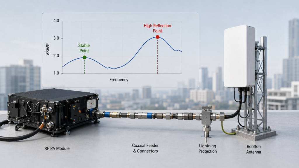
4. How Do Feeder Length, Connectors, and Lightning Protection Shift VSWR Behavior?
Feeder length, connectors, adapters, bulkhead ports, and lightning protection can shift VSWR behavior because each RF transition adds frequency-dependent impedance changes. These changes may only become visible at certain operating points within the RF Power Amplifier Frequency Range.
Fixed-site C-UAS systems are more exposed to this issue than short bench setups. They often use long feeder paths, outdoor antennas, cabinet transitions, lightning arresters, and multiple mechanical RF interfaces.
Why does feeder length matter?
A feeder cable is not only a power delivery path. Its length, loss, impedance, and phase behavior vary with frequency. A long feeder connected to a non-ideal load can make reflected-power behavior more visible at certain frequencies.
This does not mean every long cable creates VSWR failure. It means long fixed-site RF paths require frequency-point testing.
Why do connectors and transitions matter?
Each connector, adapter, waterproof joint, cabinet feedthrough, or bulkhead port can introduce a small impedance discontinuity. At lower frequencies, that discontinuity may be less visible. At higher frequencies or in wideband systems, the same discontinuity can become more important.
A high-band PA path should be reviewed with feeder length, connector quality, antenna match, and reflected-power status because high-band installations can expose frequency-specific VSWR problems.
What about lightning protection?
Fixed sites often require lightning protection. That protection is necessary, but it also has its own rated frequency range, insertion loss, power handling, and match behavior. If the lightning arrester is not well matched to the PA and antenna system, certain frequencies may show higher reflected power.
Key Takeaway: The installed RF path can create frequency-specific VSWR even when the PA module is healthy.
| RF Path Element | What Can Happen |
|---|---|
| Long feeder | Frequency-dependent loss and phase effects |
| Adapter stack | Small discontinuities accumulate |
| Bulkhead port | Cabinet transition changes impedance |
| Lightning arrester | Match may vary by frequency |
| Cable bend | Local impedance change |
| Outdoor joint | Water or contamination risk |
This table helps engineers look beyond the PA module when VSWR appears only at selected frequency points.
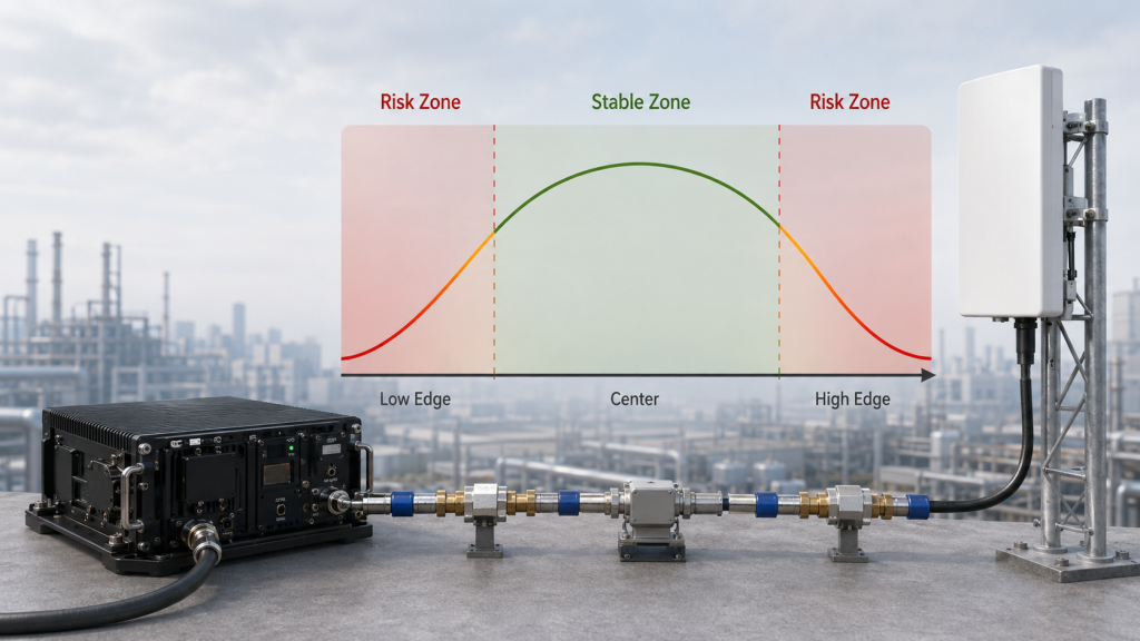
5. What Causes Frequency-Specific VSWR at Band Edges
Band edges often show VSWR and reflected-power problems first because PA matching, antenna bandwidth, filter response, and RF path transitions may all have less margin near the same frequency boundary. That makes band edges critical when judging RF Power Amplifier Frequency Range.
A module may perform well at the center of its rated band but become more sensitive near the low or high end. When the real antenna path is added, the edge point may show reflected-power behavior that was not obvious during center-frequency testing.
Why are PA and antenna edges risky together?
The PA has its own effective operating range. The antenna has its own match range. Filters, switches, combiners, and lightning protection also have frequency-response boundaries.
If a project target point sits near several boundaries at once, the system can lose margin quickly:
- PA output network near its edge
- Antenna match near its edge
- Filter response near transition
- Connector path more sensitive
- Feeder loss higher
- VSWR alarm threshold closer
Band-edge output should be checked together with reflected-power behavior because edge frequencies often have less PA, antenna, and filter margin.
What should engineers test?
Engineers should test low edge, center point, high edge, and every project target frequency close to a boundary. If the C-UAS system depends on an edge frequency, that point should not be approved by center-frequency data.
Key Takeaway: Band-edge VSWR is not guaranteed to fail, but it must be verified separately.
| Edge Condition | Why It Matters |
|---|---|
| PA low edge | Matching margin may be lower |
| PA high edge | Output and load sensitivity may increase |
| Antenna edge | VSWR may rise near bandwidth limit |
| Filter transition | Reflected power may increase |
| Multiple boundaries | Risks can stack at one frequency |
| Target near edge | Needs acceptance evidence |
This table shows why frequency-specific VSWR often appears near the edges of the operating range.
6. How Can Power Level Expose Frequency-Specific VSWR?
Power level can expose frequency-specific VSWR because a marginally matched frequency point may pass low-power testing but trigger reflected-power alarms under high RF output. This means RF Power Amplifier Frequency Range should be reviewed under the output power level the fixed-site C-UAS system will actually use.
Low-power VNA checks and low-power sweeps are useful, but they do not always represent high-power operation. A frequency point that looks acceptable during low-level measurement may create more serious reflected-power stress when the PA is driven to operational output.
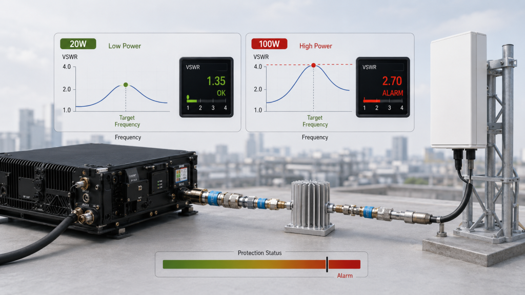
Why does high power change the reflected-power risk?
A small mismatch may look acceptable during low-power testing. When output power increases, reflected power also increases in absolute terms. For high-power RF PA modules, the same VSWR ratio can represent a much larger reflected-power condition.
That difference matters because protection circuits do not only care about the idea of mismatch. They respond to real reflected power, device stress, and protection thresholds.
Engineers should ask for:
- VSWR or reflected-power data at target frequency points
- Output power at the same points
- Protection status during high-power operation
- Alarm threshold and recovery behavior
- Test reference point
- Load condition
Why do duty cycle and operating duration still matter?
A short high-power pulse may not reveal the same risk as a sustained operating condition. Fixed-site C-UAS systems may remain active or ready for long periods, so reflected-power behavior should be checked under a duty cycle that reflects the project requirement.
Temperature can still be part of this picture, but it should not distract from the main point: a frequency point that passes low-power matching may still fail high-power reflected-power validation.
A broad mid-band PA path should be checked at target and edge frequency points because wideband coverage does not automatically prove safe VSWR behavior under the installed antenna load.
Key Takeaway: Low-power VSWR checks are useful, but high-power reflected-power evidence is more relevant for fixed-site C-UAS approval.
| Test Condition | What It May Hide |
|---|---|
| Low-power sweep | High-power reflected-power stress |
| Cold-state test | Long-duty protection behavior |
| Short test | Sustained reflected-power accumulation |
| Center-frequency check | Edge-frequency VSWR |
| VSWR value only | Real reflected-power level |
| No alarm log | Protection category uncertainty |
This table helps engineers decide when simple VSWR data is not enough for high-power fixed-site approval.
7. What Should Engineers Check When VSWR Alarms Only at One Frequency?
When VSWR alarms appear at only one frequency, engineers should compare dummy-load behavior, antenna match, feeder path, filter transition, power level, operating state, and alarm category before blaming the RF PA module. A single-frequency alarm is often a clue that the full RF Power Amplifier Frequency Range has not been verified under the real load path.
This section is not a repair manual. It is an engineering decision framework for selection, acceptance, and site validation.

What should be checked first?
The first question is reference point. Did the alarm appear at the PA port, feeder end, antenna port, cabinet output, or system monitoring interface? Different reference points point to different causes.
Engineers should check:
- Test reference point
- Dummy load behavior
- Antenna VSWR curve
- Feeder and connector path
- Lightning protection and bulkhead ports
- Filter, switch, or combiner transition
- Output power level
- Operating duration and thermal state
- Alarm category and threshold
If the same frequency works on a dummy load but alarms on the installed path, the antenna and feeder system should be investigated. If it alarms even on the dummy load, the PA output path, protection threshold, or test setup may need review.
Why does alarm category matter?
Some systems report a general alarm without separating VSWR, temperature, voltage, current, or shutdown states. That creates confusion during acceptance.
RF Power Amplifier alarm threshold files help engineers separate VSWR, temperature, voltage, current, and shutdown states during target-frequency acceptance.
Key Takeaway: A one-frequency VSWR alarm should start a structured RF path review, not an immediate PA replacement.
| Check Item | What It Helps Confirm |
|---|---|
| Dummy load retest | PA-only behavior |
| Antenna VSWR curve | Load mismatch point |
| Feeder inspection | Cable and connector issue |
| Filter path | Transition-zone risk |
| Power level | Reflected-power severity |
| Operating state | Long-duty trigger |
| Alarm category | True protection cause |
This table gives engineers a practical sequence for investigating frequency-specific VSWR alarms.
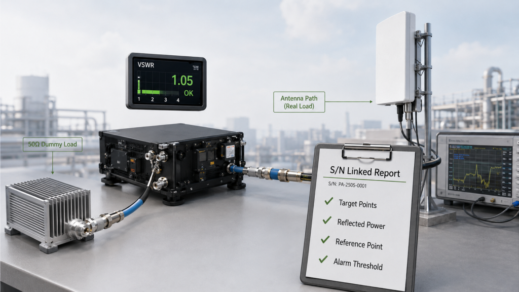
8. What Evidence Proves Frequency-Specific VSWR Is Safe
VSWR safety across the required RF Power Amplifier Frequency Range should be proven by target-frequency reflected-power data, band-edge checks, antenna-path comparison, high-power operation, alarm thresholds, and S/N-linked test reports. A single “with VSWR protection” statement is not enough.
The purpose of test evidence is not to guarantee that no field issue will ever occur. The purpose is to reduce avoidable uncertainty before a fixed-site C-UAS system is accepted.
What evidence should engineers request?
Useful evidence includes:
- Target-frequency VSWR or reflected-power data
- Low-edge and high-edge checks
- Dummy load versus antenna-path comparison
- Output power at each tested frequency
- Reflected-power status at high power
- Operating duration or duty-cycle condition
- Alarm threshold and protection response
- Output reference point
- S/N-linked test report
If the main concern is general RF Power Amplifier VSWR failure, engineers should also review how VSWR protection, reflected-power alarms, shutdown, and recovery logic are defined.
Why is reference point so important?
PA-port, feeder-end, cabinet-output, and antenna-port data are not the same. If a supplier tests at the PA port and the site accepts at the antenna port, both sides may be discussing different RF conditions.
Many fixed-site disputes happen because the supplier reports PA-port behavior while the integrator or end user judges antenna-port or installed-path behavior. The test report should clearly state where output power, VSWR, and reflected power are measured.
Key Takeaway: VSWR evidence should connect frequency, power, load, reference point, alarm threshold, and protection response.
| Evidence Type | Why It Matters |
|---|---|
| Target-frequency data | Proves actual operating points |
| Edge-frequency checks | Finds boundary risk |
| Reflected power | Shows real high-power stress |
| Dummy load comparison | Separates PA and path behavior |
| Reference-point statement | Prevents acceptance disputes |
| Alarm threshold | Defines protection boundary |
| S/N report | Supports field traceability |
This table shows what evidence is useful before approving a fixed-site RF PA path.
9. How to Define Frequency-Specific VSWR in an RFQ
RFQ documents should define frequency-specific VSWR by target points, antenna path, feeder length, output reference point, reflected-power limits, alarm thresholds, protection response, and test-report evidence. Without those details, RF Power Amplifier Frequency Range remains only a label.
A weak RFQ might say: “Need wideband RF PA module, 100W, with VSWR protection.” That sounds complete, but it leaves the most important questions unanswered.
What should a stronger RFQ include?
A stronger RFQ should define:
- Required frequency range
- Target frequency points
- Band-edge points
- Antenna type or antenna band
- Feeder length
- Connector and adapter path
- Lightning protection device
- Output reference point
- Required output power
- Duty cycle
- Expected load condition
- Reflected-power limit
- VSWR alarm threshold
- Protection response
- Alarm feedback method
- Operating-state test condition
- Test report format
- S/N-linked data requirement
This does not need to become a legal document. It should be a clear engineering boundary so the supplier, integrator, and end user know what is being approved.
Why does fixed-site C-UAS need this clarity?
Fixed-site low-altitude security systems often include outdoor antennas, long feeder paths, lightning protection, multiple RF interfaces, and long operating cycles. These factors can make one frequency behave differently from another.
The RFQ should also define where acceptance is judged. If the supplier assumes PA-port testing but the project owner expects antenna-port or installed-path acceptance, both sides may think the same frequency has passed or failed for different reasons.
Key Takeaway: A good RFQ turns “VSWR protection required” into measurable target-frequency acceptance conditions.
| Weak RFQ Line | Better RFQ Requirement |
|---|---|
| “With VSWR protection” | Threshold and response behavior |
| “Wideband module” | Target and edge frequency points |
| “Outdoor antenna” | Antenna band and load condition |
| “Long feeder” | Feeder length and reference point |
| “High power” | Reflected-power limit |
| “Test report” | S/N-linked frequency data |
This table helps buyers define VSWR requirements before approving the RF PA system.
10. How Can Source-Factory Review Reduce Frequency-Specific VSWR Risk?
Source-factory review reduces RF Power Amplifier Frequency Range risk by aligning target points, antenna load, feeder path, protection thresholds, alarm feedback, and repeatable reflected-power test evidence before fixed-site C-UAS deployment. It does not replace site validation, but it can reduce avoidable mismatch between module selection and real RF path behavior.
The key is early alignment. Frequency-specific VSWR risk is not solved by buying a module that simply says “with VSWR protection.” It must be reviewed as a system condition.
What can be reviewed before approval?
As a source factory for RF Power Amplifier modules and C-UAS core components, RF SKYPOWER can help integrators review target frequency points, antenna load, feeder path, VSWR / reflected-power behavior, protection thresholds, control feedback, and repeatable test evidence before fixed-site deployment.
A practical review may include:
- Target operating points
- PA frequency range
- Output power requirement
- Antenna load condition
- Feeder length and connector plan
- Lightning protection
- VSWR alarm threshold
- Protection response
- Control feedback
- S/N-linked report requirements
How should product and site choices connect?
If a system needs wide mid-band coverage, the PA path should be checked at target and edge points under the real antenna load. If the system needs high-band operation, feeder length, connector quality, lightning protection, and antenna match become even more important. If the project only needs fixed target frequencies, a narrower or segmented RF path may sometimes be easier to validate.
An airport perimeter case can show why controlled RF paths, protected communications, antenna sectors, and verified output points matter before high-power PA approval.
Key Takeaway: Source-factory review is most useful when it connects module behavior with antenna-load and reflected-power evidence before shipment.
| Review Area | Risk Reduced |
|---|---|
| Target frequency points | Wrong test points |
| Antenna load | Hidden mismatch |
| Feeder path | Installed-path surprises |
| Protection threshold | Unclear alarm behavior |
| Reflected-power data | Unknown high-power stress |
| Control feedback | Silent protection response |
| S/N report | Poor field traceability |
This table gives integrators a practical framework for reducing frequency-specific VSWR risk before fixed-site deployment.
FAQ
Why does VSWR only appear at one frequency?
VSWR can appear at one frequency because antenna match, feeder length, connectors, filters, lightning protection, PA band edges, and installed structures are all frequency-dependent. One frequency may be well matched while another sits near a mismatch or transition point.
Does a dummy load test prove the antenna path is safe?
No. A dummy load test proves PA behavior under a clean 50Ω load. It does not prove the installed antenna, feeder, connector stack, lightning protection, or fixed-site mounting environment.
Should engineers test VSWR at band edges?
Yes. Band edges often have less PA, antenna, filter, and path margin than center-frequency points. If a project target frequency is near an edge, it should be tested separately.
What should be included in a VSWR test report?
A useful report should include target frequency points, reflected power, output power, load condition, reference point, VSWR alarm threshold, protection response, operating-state condition, duty cycle, and S/N-linked data.
Is VSWR protection enough for fixed-site C-UAS systems?
No. VSWR protection helps protect hardware, but it does not prove that each target frequency remains usable under the real antenna load. Engineers still need target-frequency reflected-power evidence.
Conclusion
VSWR problems often appear at specific frequencies because antennas, feeder length, connectors, lightning protection, filter transitions, PA band edges, power level, and installation reference points do not behave identically across the rated RF Power Amplifier Frequency Range. For fixed-site C-UAS systems, engineers should verify target-frequency reflected power, antenna-path behavior, alarm thresholds, and protection status before accepting the module and RF path.
A specific-frequency VSWR alarm does not automatically mean the entire RF PA module is defective. It may point to antenna match, feeder length, connector discontinuity, lightning protection, filter transition, reference-point mismatch, or a band-edge condition that only appears at one operating point. That is why engineers should separate PA-only dummy-load behavior from installed-path reflected-power behavior before making a selection or failure judgment.
As a source factory for RF Power Amplifier modules and C-UAS core components, RF SKYPOWER can support target-frequency reflected-power review, VSWR / temperature / voltage protection, control feedback, and S/N-linked test reports. Before approving RF Power Amplifier modules for fixed-site low-altitude security, prepare the target frequency points, antenna path, feeder length, connector plan, lightning protection, output reference point, reflected-power limits, VSWR alarm threshold, duty cycle, and test-report expectations for engineering review.
If your team is preparing a fixed-site C-UAS deployment, contact us today to review frequency-specific VSWR risk before field installation turns one target point into a recurring alarm.