


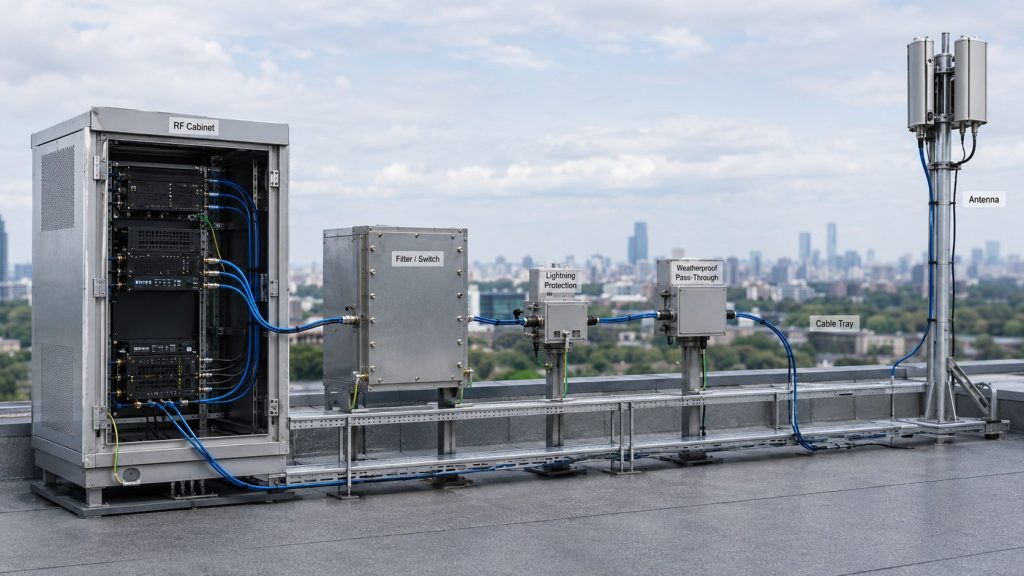
A drone jammer module is a product term often used by buyers who are looking for the RF core of a counter-UAS mitigation system. In engineering terms, it is not a complete anti-drone solution by itself; it is usually one part of a controlled RF chain that may include an SDR or signal source, RF Power Amplifier Modules, filtering or switching paths, antennas, power supply, cooling, protection feedback, and system-level control.
For system integrators, the real question is not only what the module is called, but what role it plays in the C-UAS architecture. Frequency range, usable output power, duty cycle, antenna path, VSWR and thermal protection, control interface, and repeatable test data decide whether the module can support a project requirement. A high-output module with unclear cooling, alarm feedback, or test conditions can create more integration risk than value.
This article explains what a drone jammer module means as an RF core component inside a professional C-UAS system, how it differs from a complete anti-drone system, how RF Power Amplifier Modules fit into the mitigation chain, and what engineers should confirm before moving from product search to RFQ.
1. What a Drone Jammer Module Means in RF Integration
A drone jammer module usually means an RF module or RF power stage that supports the mitigation side of a counter-UAS system. For engineering review, it is better understood as a C-UAS RF module, anti drone RF module, or RF core component rather than a complete standalone solution.
Here’s the useful distinction: the module is only valuable when its role in the RF chain is clear. A vague product name does not tell you its frequency range, output reference point, duty cycle, cooling requirement, antenna compatibility, or protection behavior.
What is the module’s real job?
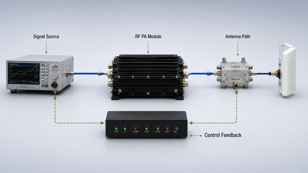
The module’s job is to support one part of the RF mitigation path. Depending on the design, it may work with a signal source, RF PA stage, switching path, filter, antenna, control interface, and alarm feedback.
A serious review should ask:
- What part of the RF chain does this module cover?
- Is it a power amplifier stage or a larger RF assembly?
- Which frequency range is supported?
- What output level is specified?
- What cooling condition is required?
- What control and alarm feedback is available?
- What test evidence supports the claim?
Why is the product name not enough?
“Drone jammer module” is a search term, not a complete engineering specification. Two products using the same term may have very different internal roles, output levels, thermal limits, and integration requirements.
Key Takeaway: A drone jammer module should be evaluated by its role in the RF chain, not by the product name alone.
| Product Term | Better Engineering Question |
|---|---|
| Drone jammer module | Which RF chain function does it support? |
| Anti drone module | Is it RF PA, signal control, antenna path, or assembly? |
| High power module | At which reference point and duty cycle? |
| Wideband module | Which target points were tested? |
| Integrated module | What control and protection feedback is visible? |
This table helps buyers move from product wording to real module evaluation.
2. How Is a Drone Jammer Module Different from a Complete C-UAS System?
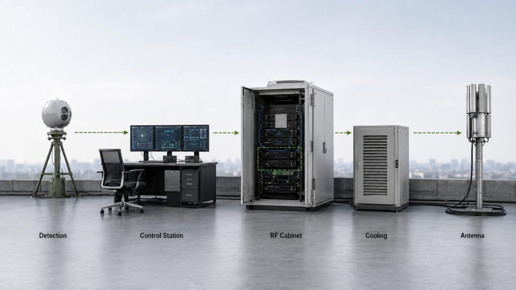
A drone jammer module is different from a complete C-UAS system because the module supports only part of the mitigation chain, while the full system includes detection, assessment, control logic, RF signal management, RF amplification, antennas, power, cooling, operator workflow, and acceptance evidence.
This is where many early RFQs become unclear. A buyer may ask for a module, but the project actually needs a system architecture decision.
What belongs to the system, not the module?
A complete C-UAS solution may include many layers that sit outside the module itself. The RF module is one important part, but it cannot define the entire system alone.
System-level items may include:
- Detection sensor input
- Target assessment workflow
- Control software
- Signal source or SDR
- RF Power Amplifier Modules
- Filter or switching paths
- Antenna system
- DC power supply
- Thermal design
- Protection feedback
- Operator interface
- Test and acceptance process
In Low-Altitude Security & C-UAS EW systems, RF modules are reviewed together with detection, control, RF amplification, antennas, protection, and verification evidence.
Why does this difference matter for buying?
If the buyer only asks for a “drone jammer module,” the supplier may not know whether the project needs a bare RF PA module, an RF assembly, a broadband power stage, an antenna path, or a larger subsystem. That makes quotation inaccurate.
Key Takeaway: A module can support the RF chain, but the system architecture decides whether it can be used effectively.
| Area | Module-Level View | System-Level View |
|---|---|---|
| RF output | One RF stage | Complete controlled RF path |
| Signal source | External or integrated | Linked to control logic |
| Antenna | Load interface | Coverage and installation design |
| Power | DC input | Cabinet power architecture |
| Cooling | Module thermal path | Platform-level heat management |
| Feedback | Alarm or status line | System response and diagnostics |
This table helps prevent buyers from treating one module as the whole C-UAS solution.
3. How to Evaluate a Drone Jammer Module RF PA Stage
A drone jammer module often depends on an RF Power Amplifier Module because the PA stage raises a controlled RF signal to the required output level inside the mitigation chain. The RF PA does not define the whole system, but it strongly affects usable output, heat, protection behavior, and integration risk.
Here’s the engineering point: if the RF PA stage is weak, mismatched, poorly cooled, or poorly documented, the rest of the RF chain becomes harder to validate.
What does the RF PA stage decide?
The RF Power Amplifier Module affects several project-critical items. It is not only a “wattage block.”
Engineers should review:
- Frequency range
- Rated and usable output power
- Gain and gain flatness
- Input drive condition
- Supply voltage and current
- Duty cycle
- Thermal behavior
- VSWR protection
- Control feedback
- Mechanical and cooling requirements
- Test report availability
Engineers evaluating a drone jammer module as part of a professional C-UAS project should review RF Power Amplifier Modules as the controlled RF power stage inside the system architecture.
Why is higher wattage not always better?
Higher output may increase thermal load, DC current demand, antenna-path stress, and reflected-power risk. A lower-power module with clearer test data and better thermal fit may be easier to integrate than a higher-power module with vague conditions.
Key Takeaway: The RF Power Amplifier Module is often the most important RF power stage, but it must be judged by conditions, not wattage alone.
| RF PA Factor | Why It Matters |
|---|---|
| Frequency range | Must match project band plan |
| Output power | Must be usable under real conditions |
| Gain flatness | Affects multi-band consistency |
| Duty cycle | Defines thermal stress |
| Supply current | Drives power design |
| VSWR protection | Helps manage antenna mismatch |
| Test report | Supports RFQ and acceptance |
This table helps buyers evaluate the RF PA stage as an engineering component, not a simple power number.
4. How Do SDR, Signal Source, and Control Logic Fit?
A drone jammer module may work with an SDR, signal source, or control unit that defines how the RF chain is managed inside the system. The module may provide RF power capability, but signal control and system command logic decide how the module fits into the larger architecture.
This is where integrators should avoid oversimplifying the module. RF output hardware and control logic must be reviewed together.
What does the signal source control?
The signal source or SDR may define waveform management, timing, control coordination, and integration with the wider C-UAS platform. The public discussion should stay at system-role level, but the RF chain still needs a clear interface between signal source and PA stage.
A review may include:
- Signal source compatibility
- Input drive level
- Control interface
- Enable logic
- Timing requirements
- Fault response
- System command structure
- Documentation availability
SDR signal source and control logic should be aligned with the RF Power Amplifier Module so the C-UAS system follows the project frequency plan and operator workflow.
Why does control feedback matter?
A module that cannot report status clearly is difficult to manage in a multi-module system. If the system cannot distinguish normal operation from VSWR alarm, temperature warning, voltage issue, or shutdown state, troubleshooting becomes slower.
Key Takeaway: RF power hardware needs control logic and status feedback before it becomes a useful system component.
| Control Item | Engineering Value |
|---|---|
| Enable logic | Supports safe startup |
| Input drive definition | Prevents mismatch with signal source |
| Alarm feedback | Helps fault diagnosis |
| Temperature status | Supports thermal control |
| VSWR status | Supports antenna-path protection |
| Interface document | Supports integration planning |
This table helps engineers connect the module to the control side of the system.
5. How to Check Drone Jammer Module Frequency and Output
A drone jammer module should be reviewed by frequency range and usable output, not only by broad coverage claims. Frequency range shows where the module is designed to operate, while usable output depends on target frequency, input drive, load condition, thermal state, duty cycle, and output reference point.
The practical risk is simple: a module can look strong on paper but still be weak at the project’s actual target points.
What should frequency range prove?
Frequency range should show whether the module is even a candidate for the project. It does not prove equal output across the band.
Ask:
- Is the target range inside the rated band?
- Are low, center, and high points shown?
- Are project target points tested?
- Does output drop near band edges?
- Is gain flatness available?
- Is thermal behavior checked at important points?
What should output power prove?
Output power should prove what the module can deliver under defined conditions. A wattage claim without test frequency, supply voltage, input drive, cooling condition, and duty cycle is incomplete.
Key Takeaway: Frequency range and output power are useful only when the test conditions and reference points are clear.
| Datasheet Claim | Better Check |
|---|---|
| Wide frequency range | Which points were measured? |
| High output | At what load and duty cycle? |
| Typical power | Which frequency and input drive? |
| Full-band module | Is full-band sweep data available? |
| Stable output | Was it hot-state or short test? |
| Usable system power | PA port or antenna path reference? |
This table helps engineers avoid treating broad coverage and wattage as final proof.
6. Why Are Broadband RF PA Modules Common in C-UAS RF Chains?
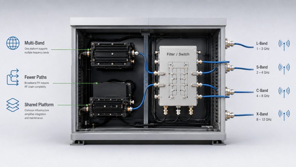
A drone jammer module may use broadband RF PA modules because professional C-UAS RF chains often need flexible multi-band architecture. Broadband PA modules can reduce the number of separate RF paths in some designs, but their output, heat, VSWR behavior, and antenna match still need target-point verification.
This is where broadband modules are useful but often misunderstood. Broadband means architectural flexibility; it does not automatically mean equal performance everywhere.
When does broadband help?
Broadband RF PA modules can help when the system needs fewer hardware paths, easier module-family sourcing, or wider planning margin.
They may support:
- Multi-band architecture
- Reduced module count
- Shared cabinet design
- Simplified control layout
- Future upgrade margin
- Faster product-family comparison
A 300–2700MHz RF Power Amplifier Module can be reviewed for multi-band C-UAS RF chain design, but target-frequency output, duty cycle, antenna path, and protection behavior still need verification.
What changes at higher frequency ranges?
At higher frequency ranges, feeder loss, connector quality, antenna match, and thermal behavior become more visible. A 2000–6000MHz RF Power Amplifier Module should be evaluated with high-band antenna paths, feeder loss, hot-state output, VSWR behavior, and repeatable test evidence.
Key Takeaway: Broadband PA modules can simplify architecture, but test data decides whether the target points are actually usable.
| Broadband Benefit | Required Check |
|---|---|
| Wider band coverage | Target-point output |
| Fewer module paths | Thermal and current margin |
| Shared platform | Control compatibility |
| Easier product planning | Frequency-specific data |
| High-band capability | Feeder and antenna loss |
| Flexible architecture | Acceptance evidence |
This table helps buyers use broadband modules for system planning without overreading the datasheet.
7. What Anti Drone Module Protection Details Matter
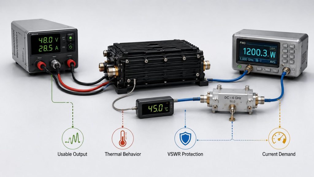
A drone jammer module should be reviewed for protection, cooling, and power behavior because high RF output creates electrical and thermal stress. VSWR protection, temperature protection, voltage protection, current demand, alarm feedback, and cooling conditions decide whether the module can stay within a safe operating boundary.
Here’s the field reality: most integration problems do not come from the product name. They come from heat, mismatch, power margin, and unclear alarm behavior.
Which protection details should be visible?
The module review should confirm how the RF stage reacts to abnormal conditions. “Protected” is not enough.
Ask about:
- VSWR or reflected-power protection
- Over-temperature protection
- Over-voltage protection
- Alarm output
- Derating behavior
- Shutdown behavior
- Recovery logic
- Fault category feedback
- Protection status in test reports
Why do cooling and power change the result?
A module that performs well in a short open-bench test may behave differently in a closed cabinet, hot environment, or long-duty profile. DC power reserve also affects whether the module can hold output under load.
Key Takeaway: Protection, cooling, and power design turn an RF module from a rated component into an integratable component.
| Detail | Integration Risk if Unclear |
|---|---|
| VSWR protection | Antenna mismatch response is unknown |
| Temperature protection | Heat failure mode is unclear |
| Voltage protection | Power abnormality response is unclear |
| Current demand | Supply design may be undersized |
| Cooling method | Hot-state output may drop |
| Alarm category | Fault diagnosis becomes slow |
This table helps engineers locate the most common RF module integration risks before sample testing.
8. How Do Antennas and RF Paths Affect Module Value?
A drone jammer module cannot be evaluated without the antenna and RF path because the module output must pass through connectors, cables, filters, switching paths, and antennas before it becomes useful in the system. The RF PA stage may be strong, but a poor RF path can reduce usable output or trigger reflected-power problems.
The better check is simple: treat the antenna path as part of module evaluation, not as a later accessory.
What should the antenna path include?
A complete RF path review may include:
- RF output connector
- Adapter count
- Coaxial cable type
- Feeder length
- Filter or switch loss
- Antenna type
- Antenna match
- Mounting location
- VSWR or reflected power
- Power handling
- Environmental condition
High power wideband antenna selection should follow the project frequency plan because RF PA output only becomes useful when the antenna path is matched, controlled, and verified.
Why does this affect module comparison?
Two modules with similar output ratings may perform differently once connected to the real RF path. Higher-frequency paths may show more feeder loss. Wideband systems may need different antenna strategies across ranges. Poor connector quality can also change reflected power.
Key Takeaway: Module value depends on the full RF path from PA output to antenna behavior.
| RF Path Item | Why It Matters |
|---|---|
| Cable loss | Reduces usable output |
| Adapter count | Adds reflection and loss |
| Antenna match | Affects VSWR and reflected power |
| Filter path | Changes output reference |
| Mounting location | Affects system planning |
| Power handling | Protects high-output paths |
| Environmental exposure | Affects long-term stability |
This table helps integrators compare module output against real RF-chain behavior.
9. What Test Data Supports a Drone Jammer Module Claim
A drone jammer module claim should be supported by repeatable test evidence, not only by product wording, photos, or headline power. Engineers should look for frequency, output, gain, current, thermal, VSWR, duty-cycle, protection, and S/N-linked data before final RFQ or sample approval.
This is where a product claim becomes an engineering discussion. The stronger the evidence, the easier it is to compare suppliers.
What data should engineers request?
Useful evidence may include:
- Tested frequency points
- Output power at target points
- Gain and gain flatness
- Supply voltage
- Current draw
- Duty condition
- Cooling method
- Temperature behavior
- VSWR or reflected power
- Protection status
- Load condition
- Test duration
- S/N-linked report
- Acceptance boundary
An RF Power Amplifier Module datasheet should be reviewed for frequency range, output, gain, VSWR protection, duty cycle, thermal data, control feedback, and test evidence before RFQ.
What should stay in engineering communication?
Some details are better handled through formal engineering communication, such as custom interface files, special test requirements, project-specific limits, or non-public configuration details. The article should not need to expose those details to explain what evidence buyers should ask for.
Key Takeaway: Test evidence separates a credible RF module offer from a vague product label.
| Claim | Stronger Evidence |
|---|---|
| Wide frequency range | Target-point data |
| High output | Test condition and duty cycle |
| Stable module | Hot-state behavior |
| Protected design | Fault response record |
| Easy integration | Control documentation |
| Reliable production | S/N-linked report |
This table helps procurement teams ask for evidence without turning the RFQ into guesswork.
10. How to Move from Drone Jammer Module Search to RFQ
A drone jammer module search should move into an RFQ that defines the RF core component requirement clearly. Instead of asking for a generic module, engineers should describe project type, frequency range, output target, duty cycle, antenna path, cooling condition, control interface, protection needs, and test-report expectations.
This is the final commercial step: translate a broad search term into a supplier-ready engineering request.
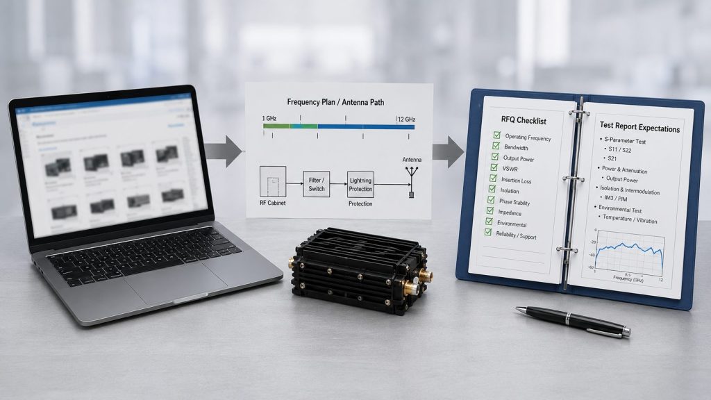
What should the RFQ include?
A stronger RFQ should include:
- Project type
- Target frequency range
- Target frequency points
- Required output
- Expected duty cycle
- Antenna type
- Feeder length
- Cooling method
- Supply voltage
- Control interface need
- VSWR / temperature / voltage protection
- Alarm feedback requirement
- Test report expectation
- Quantity
- Customization need
- Confidentiality requirement
If the project has moved from the term “drone jammer module” to RF core component selection, engineers should review the RF Power Amplifier Module selection guide before RFQ.
How can a source factory support the review?
As a source factory for RF Power Amplifier Modules and C-UAS core components, RF SKYPOWER can help integrators review frequency range, output target, duty cycle, antenna path, cooling condition, protection behavior, control interface, and repeatable test evidence.
Key Takeaway: The best next step is not a vague product request; it is a clear RFQ that defines how the module will be integrated and tested.
| RFQ Field | Why It Matters |
|---|---|
| Frequency range | Defines candidate module family |
| Output target | Defines RF power stage |
| Duty cycle | Defines thermal stress |
| Antenna path | Defines real load condition |
| Cooling method | Defines hot-state behavior |
| Protection needs | Defines safety response |
| Control interface | Supports system integration |
| Test report | Supports acceptance evidence |
This table turns a broad module search into a practical engineering RFQ.
FAQ
Is a drone jammer module a complete anti-drone system?
No. It is usually one RF-related component or power stage. A complete C-UAS system also needs detection, control logic, signal management, antennas, power supply, cooling, operator workflow, and acceptance evidence.
What should I check before requesting a drone jammer module quote?
Start with frequency range, required output, duty cycle, antenna path, cooling method, supply voltage, protection behavior, control interface, and test-report requirements. These details make the RFQ clearer.
Is an RF Power Amplifier Module the same as a jammer module?
No. An RF Power Amplifier Module is usually the controlled power stage inside a larger RF chain. It does not replace the signal source, antenna system, control logic, or system acceptance process.
Why are broadband RF PA modules used in C-UAS RF chains?
Broadband RF PA modules can support flexible multi-band architecture and reduce module-path complexity. However, target-frequency output, heat, VSWR behavior, and antenna-path performance still need verification.
What test data should support an anti drone module claim?
Look for target-frequency output, gain, gain flatness, current, duty cycle, temperature behavior, VSWR or reflected-power response, protection status, load condition, and S/N-linked reports.
Conclusion
A drone jammer module should be understood as an RF core component, not as a complete anti-drone system or a simple product label. Its real value depends on where it sits in the RF chain, how the RF Power Amplifier Module is selected, how the signal source and control logic connect, how the antenna path behaves, and whether output, duty cycle, cooling, protection, and test evidence match the project requirement.
This article reframed the term “drone jammer module” into engineering language: RF power stage, C-UAS RF module, anti drone RF module, broadband PA path, protection feedback, antenna compatibility, and RFQ-ready evidence. That shift helps engineers and buyers compare modules by system value rather than by vague product wording.
RF SKYPOWER provides RF Power Amplifier Modules and C-UAS core components for system integrators and professional security projects. If your team is reviewing RF core components, contact us today to discuss frequency range, output target, duty cycle, antenna path, cooling condition, protection logic, control feedback, and test-report expectations.
Reliable C-UAS RF integration starts with a clear module role, verified RF data, and a system architecture that can be tested before deployment.