










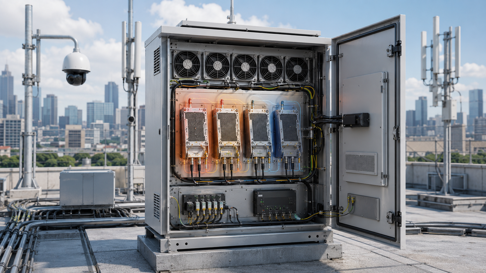
A multi-PA cabinet can pass a quick thermal check and still hide a shared-heatsink problem. Shared heatsink thermal zoning matters because one module may start from a warmer local baseplate, sit in a weaker airflow zone, or receive heat conducted from a neighboring high-duty PA even when the overall heatsink looks large enough.
That means a single cabinet-temperature reading, an open-door test, or a short single-PA run cannot show whether every module still has acceptable thermal margin after the real operating combination reaches a stable hot condition.
Before the layout is approved, the buyer needs to answer a more useful question: what evidence shows that each PA remains within its required hot-state limits when its own dissipation, neighboring heat, and the installed airflow path act together?
1. What Does a Shared Heatsink Mean in a Multi-PA Cabinet?
A shared heatsink is a thermal structure used by two or more RF PA modules. Depending on the mechanical design, this may be a common aluminum heatsink, copper spreading plate, cold plate, machined base, or another mounting structure that transfers heat from several modules toward the same cooling path.
Sharing the structure can reduce cabinet volume and simplify mechanical integration. But shared does not mean thermally equal.
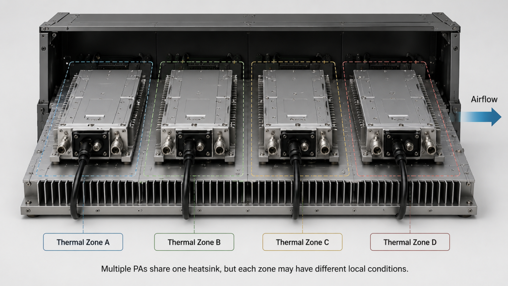
Each PA may operate under a different combination of:
- Output power
- Efficiency and resulting heat dissipation
- Frequency band
- Duty cycle
- Current draw
- Thermal-interface condition
- Mounting position
- Local airflow
- Neighboring heat sources
- Protection or derating boundary
A large common heatsink therefore cannot be approved only from its dimensions or average temperature.
The engineering review should instead ask:
- Which PA has the highest thermal dissipation under the intended operating condition?
- Which modules operate simultaneously?
- Which module sits upstream or downstream in the airflow path?
- Which region receives heat from neighboring modules?
- Where are the relevant temperature sensors located?
- Does each PA remain stable after the complete cabinet reaches its hot operating state?
| Shared-Heatsink Assumption | Better Engineering Check | Why It Matters |
|---|---|---|
| One large heatsink cools every PA equally | Review thermal dissipation and temperature by module zone | A local hotspot can be hidden by an acceptable average temperature |
| Visible heatsink size proves sufficient cooling | Review the complete heat path and operating condition | Heat removal depends on contact, spreading and airflow |
| One cabinet sensor represents every module | Map sensors to critical PA zones | A remote sensor may miss the hottest location |
| A PA that passes alone will pass in the cabinet | Compare single- and multi-module hot-state results | Neighboring modules can change the thermal starting condition |
The correct question is not whether the cabinet has a large enough piece of metal. It is whether the installed cooling structure provides enough margin at each relevant module position under the intended operating combination.
2. Why Can One PA Module Heat Another Module?
A PA does not heat only the area directly below its own baseplate.
Heat can spread laterally through the mounting plate or heatsink, while warm air from one section can change the cooling condition of another. The second PA may therefore begin its own high-power period from a higher thermal starting point than it would during an isolated bench test.
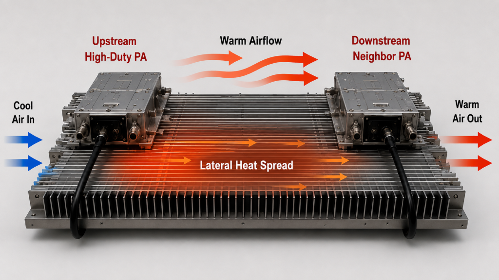
Possible coupling paths include:
- Heat spreading through the shared metal base
- Baseplate-to-heatsink conduction
- Differences in thermal pad or grease condition
- Uneven mounting contact
- Upstream-to-downstream warm airflow
- Hot-air recirculation
- Fan shadows or restricted fin passages
- Closely spaced high-duty modules
- Different duty-cycle overlaps
This matters when diagnosing an apparent PA problem.
Suppose one lower-power PA reaches an over-temperature warning only when a neighboring high-duty PA has already been operating. That observation does not by itself prove that the lower-power PA is defective.
The engineering team should compare at least:
- The same PA operating alone
- The same PA with neighboring modules active
- The zone temperature before its high-power period begins
- Its position in the cabinet
- Its current and output trend
- The timing of any protection event
If the fault follows the cabinet position or the neighboring operating state rather than the module itself, shared thermal conditions become part of the investigation.
The purpose of thermal zoning is therefore not merely to draw areas on a mechanical diagram. It is to identify how the installed thermal environment changes the operating condition seen by each module and whether the required hot-state limits are still maintained.
3. What Must a Thermal Zone Separate and Measure?
A useful thermal zone is a testable part of the cabinet whose heat source, airflow condition, sensor position and operating state can be identified.
It does not necessarily require a physical wall between modules.
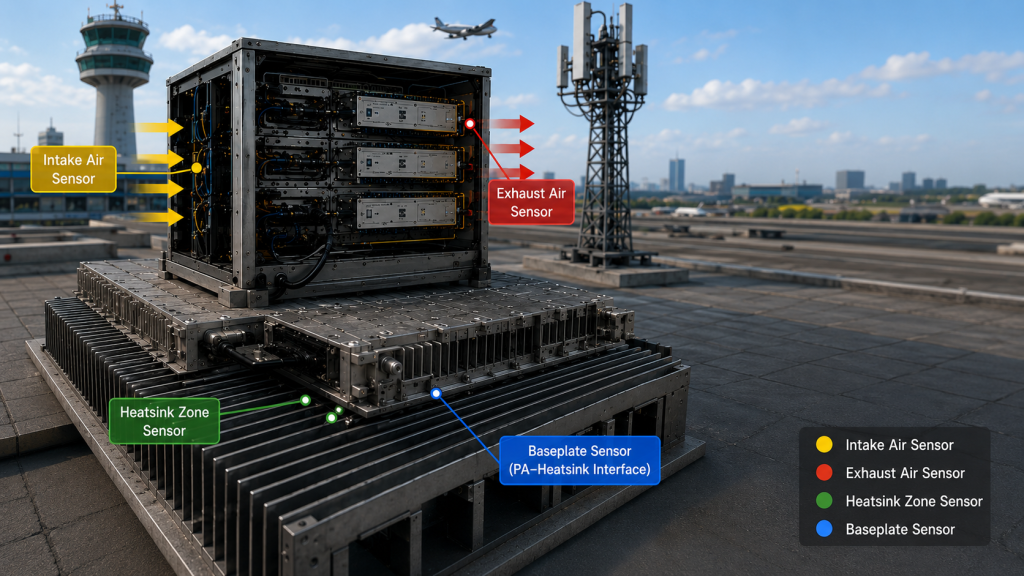
A zone can be defined around:
- One PA module
- A group of similar-duty PAs
- A high-dissipation region
- An airflow intake or exhaust region
- A downstream warm-air area
- A fan-shadow area
- A region affected by another cabinet heat source
Each zone should answer specific engineering questions.
Which heat source dominates this location?
The team should know whether the observed temperature is mainly associated with the PA installed in that position or whether neighboring devices materially change the thermal condition seen by that module.
Where is temperature actually measured?
A cabinet-air sensor, heatsink sensor and module-baseplate measurement do not represent the same location.
The test record should therefore state where each temperature value comes from rather than reporting a generic “cabinet temperature.”
What operating combination produced the result?
A zone-temperature value without module operating states is difficult to interpret.
The record should identify which PAs were active, their relevant duty-cycle condition and how long that operating state had been maintained.
Does the PA remain stable in that zone?
Temperature alone is not the final acceptance result.
The zone measurement should be reviewed together with:
- Hot-state RF output
- Current trend
- Protection or derating status
- Cooling condition
- Module position
- Neighboring module activity
The purpose is to make a thermal result locatable and repeatable instead of treating the whole cabinet as one uniform thermal environment.
4. Why Single-Module Hot Tests Can Miss Shared-Heat Risk
Testing one PA at a time is useful for module-level verification, but it does not reproduce every condition created by a shared heatsink.
A PA can behave normally when tested alone and experience a different thermal environment after other modules are operating on the same cooling structure.
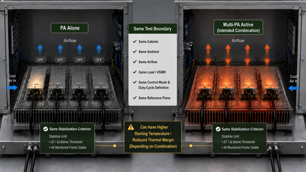
Common gaps include:
- Testing only one PA while adjacent modules are off
- Testing with the cabinet door open
- Recording output before thermal stabilization
- Ignoring duty-cycle overlap
- Recording only cabinet-air temperature
- Measuring exhaust air without checking local zones
- Using a cooling state different from the installed configuration
- Comparing tests performed under different ambient conditions
For a single-versus-multi-module comparison intended to isolate shared-heatsink effects, keep the ambient condition, RF load or VSWR boundary, cooling configuration and control mode, duty-cycle definition, output-measurement reference plane, and stabilization criterion consistent unless one of those variables is intentionally being evaluated.
Treat zone temperature, current, hot-state Pout, and protection behavior as measured results rather than controlled inputs.
Otherwise, a difference between two runs may show that the overall test conditions changed, but it cannot be attributed cleanly to shared-heatsink coupling.
For example, a short test immediately after cold start and a later closed-cabinet run do not isolate one variable. Temperature history, airflow, neighboring heat and operating duration have all changed.
Where hot-state output is part of acceptance, the team should define what “stabilized” means for that test rather than relying only on elapsed time. The requirement may be based on an agreed observation interval or on a defined temperature/output stability criterion appropriate to the project.
The same principle applies to fixed-site low-altitude security and C-UAS EW systems. When several modules operate for long intervals inside the final enclosure, acceptance should reproduce the installed airflow path, expected ambient boundary, realistic simultaneous operating combination and agreed stabilization condition rather than relying on a short open-cabinet run.
5. How to Diagnose Shared Heatsink Thermal Problems
The first protection alarm should not automatically become the root-cause conclusion.
Before changing the layout, fan setting, module position, mounting pressure or thermal interface, record the baseline condition. If several variables are changed before the original condition is documented, the next test may no longer isolate what caused the initial problem.
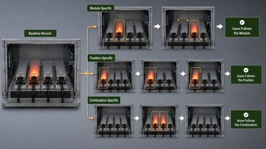
A practical diagnostic order is:
- Confirm the affected module’s frequency, output target and duty-cycle condition.
- Record its current draw and hot-state output trend.
- Identify which neighboring modules were active before and during the event.
- Record module S/N and physical slot or mounting position.
- Compare relevant baseplate and heatsink-zone temperatures.
- Check the thermal-interface installation and mounting condition.
- Confirm the actual airflow path through the heatsink fins.
- Check for cable blockage, fan shadows or warm-air recirculation.
- Compare the temperature-sensor position with the suspected hotspot.
- Review protection or derating logs against neighboring module activity.
- Repeat the same PA alone under comparable test boundaries.
- Repeat the intended multi-module operating combination after stabilization.
This order helps separate three different possibilities:
Module-specific behavior
The same PA shows the problem in different cabinet positions under comparable conditions.
Position-specific behavior
Different modules show a similar problem when installed in the same thermal zone.
Combination-specific behavior
The problem appears only when particular neighboring modules or duty cycles overlap.
Those outcomes lead to different engineering actions. A module issue should not be “fixed” by changing the cabinet if the fault follows the hardware, and a cabinet thermal problem should not be blamed on the first PA that reports an alarm.
6. What Evidence Proves Shared-Heatsink Thermal Zoning?
A mechanical drawing can show where the modules are installed, but it does not prove how the cabinet behaves after the shared cooling structure reaches its operating condition.
Useful evidence should connect the thermal result to an identifiable module, location and test boundary.
For each relevant PA, record as appropriate:
- Module S/N
- Slot or physical position
- Frequency band
- Target or measured output
- Duty-cycle condition
- Simultaneous operating combination
- Baseplate temperature
- Heatsink-zone temperature
- Intake and exhaust temperature where relevant
- Cabinet temperature
- DC voltage and current trend
- Hot-state RF output
- Protection or derating status
- Fan or cooling condition
- Thermal-interface condition
- Temperature-sensor position
- Ambient temperature
- Test duration or stabilization criterion
- RF load or VSWR condition
- RF output measurement reference plane
- Single-module versus multi-module comparison
If external cable, attenuator, coupler or connector losses are corrected in the reported RF output, the test record should also make clear whether the value is measured directly or corrected to an agreed reference plane.
That prevents a thermal comparison from being confused with a change in RF measurement method.
Shared-Heatsink Thermal Zoning Evidence Table
| Acceptance Question | Weak Evidence | Better Evidence | What the Better Evidence Can Show |
|---|---|---|---|
| Is every critical PA zone represented? | One cabinet temperature | Sensor locations tied to module positions and zone temperatures | Whether a local hotspot is hidden by the cabinet average |
| Does one PA influence another? | Single-module heat test | Comparable single- and multi-module hot-state trends under controlled boundaries | Whether neighboring operation changes the installed thermal condition |
| Is airflow represented realistically? | Open-cabinet test | Final cooling path under closed-cabinet conditions | Whether enclosure resistance or recirculation changes the result |
| Is hot-state output comparable? | One RF power number | Pout with operating state, stabilization condition and reference plane | Whether RF performance remains consistent under the defined thermal boundary |
| Can a protection event be traced? | Alarm screenshot | S/N, slot, temperature trend, neighboring state and protection log | Whether the event follows the module, position or operating combination |
| Can the result be reproduced later? | Unidentified test photo | S/N-linked report with test boundaries and configuration | Whether production, service or acceptance teams can repeat the condition |
The evidence does not need to prove that every point on a shared heatsink has the same temperature. It should prove that the critical module zones are known and that the intended operating combination does not produce an unacceptable thermal, RF-output, or protection result within the defined test boundary.
When thermal-zoning requirements affect module selection or acceptance, define the cooling method, module count, simultaneous duty-cycle condition, protection boundary and required hot-state evidence before selecting custom RF power amplifier modules.
7. How Should Thermal Zones Guide the Cabinet Layout?
Thermal zoning is most useful before module positions, airflow and sensor locations are locked.
The purpose is not to design the entire heatsink from one rule. It is to prevent the mechanical layout from creating an operating condition that the final acceptance test cannot control or explain.
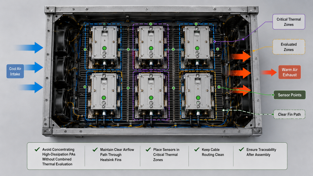
Useful layout checks include:
- Avoid concentrating multiple high-dissipation modules in one local zone without evaluating their combined thermal load and simultaneous operating condition.
- Consider separating high-duty and intermittent-duty modules where the operating combination makes this useful.
- Define airflow direction before final PA placement.
- Check whether downstream modules receive warmer inlet air.
- Keep critical heatsink passages clear of avoidable cable blockage.
- Place temperature sensors where they represent critical zones rather than convenient mounting points.
- Define how combined operation affects derating or protection limits.
- Leave enough traceability in the layout to associate module S/N, position and measured temperature.
Frequency grouping should influence thermal zoning only where different PA blocks produce meaningfully different thermal dissipation, current draw or duty-cycle overlap.
The detailed RF block arrangement belongs in the RF PA frequency-block plan. For thermal zoning, the important question is whether those operating groups create different conditions on the shared cooling structure.
Likewise, thermal-interface selection, mounting flatness and general heatsink construction should be reviewed as part of the full RF PA heatsink design. This page’s narrower concern is what changes when several PA modules share that thermal path.
A layout is therefore not better simply because the modules fit neatly. It is better when the expected heat sources, airflow path, measurement zones and combined operating states can still be verified after assembly.
8. What Should the RFQ Define for Shared-Heatsink Approval?
Terms such as “good cooling,” “large heatsink,” or “no over-temperature” are not precise acceptance requirements.
A multi-PA RFQ should define enough operating and measurement boundaries for the supplier and buyer to judge the same condition.
Shared-Heatsink RFQ Checklist
| RFQ Item | What to Define | Why It Matters | Expected Evidence |
|---|---|---|---|
| Module count and position | Number of PAs and intended slot or mounting map | Defines the heat-source arrangement | Cabinet layout or slot map |
| Frequency and RF operating point | Band, target Pout, and required measurement reference plane for each PA | Defines the RF operating condition; thermal dissipation must be evaluated from DC input and RF output or validated supplier thermal data rather than Pout alone | RF output, Vdc/Idc, and hot-state thermal record |
| Duty cycle | Expected operating state and simultaneous overlap | Defines combined thermal stress | Multi-module operating record |
| Shared cooling structure | Heatsink, plate or cold-plate arrangement | Defines the common thermal path | Mechanical or thermal-zone drawing |
| Thermal interface | Relevant TIM and mounting method | Influences baseplate-to-heatsink transfer | Assembly requirement or record |
| Airflow | Fan path, intake, exhaust and enclosure state | Defines heat removal from the shared structure | Closed-cabinet cooling record |
| Sensor locations | Measurement points by critical zone | Prevents reliance on one convenient temperature | Sensor map |
| Ambient and stabilization | Required ambient boundary plus test duration or stabilization criterion | Defines when hot-state evidence is valid | Stabilized thermal record |
| RF load / VSWR condition | Required load boundary during the test | Prevents different RF loading from being mixed with thermal comparison | Test-condition record |
| Pout reference plane | Where RF output is measured or corrected to | Makes hot-state output records comparable | Traceable RF power record |
| Protection behavior | Relevant over-temperature, voltage, current or derating condition | Shows whether combined operation approaches a protection boundary | Logged status or alarm record |
| Traceability | S/N, slot, zone and test configuration | Supports reproduction and later service review | S/N-linked test report |
A stronger RFQ therefore replaces weak statements with measurable conditions.
Instead of:
“Shared heatsink acceptable.”
Define the module combination and require comparable hot-state evidence.
Instead of:
“No over-temperature.”
Define ambient, cooling condition, simultaneous operation, stabilization criterion, sensor position and the protection boundary being checked.
Instead of:
“Output power meets specification.”
Define which module, operating state, load condition and measurement reference plane the output requirement refers to.
The goal is not to make the RFQ unnecessarily complicated. It is to remove the ambiguities that would otherwise allow a single-module or cold-state result to be interpreted as proof of the final multi-PA cabinet condition.
FAQ
Can multiple RF PA modules share one heatsink?
Yes, provided the installed shared cooling condition is verified rather than assumed. The review should consider each module’s thermal dissipation, position, airflow, duty-cycle overlap, relevant zone temperature, hot-state RF performance and protection status under the intended operating combination.
A large shared heatsink by itself does not prove that every PA has the same thermal margin.
How do I know if one PA is heating another PA?
Compare the same module under controlled single-module and multi-module conditions while recording module position, zone temperature, neighboring operating state, current, RF output and protection status.
If the temperature or protection behavior changes when a neighboring PA operates while the other relevant test boundaries remain controlled, shared-zone heating becomes a credible cause to investigate.
If the symptom follows one cabinet position across different modules, the position and cooling path deserve particular attention.
The comparison should be completed before concluding that either the PA or the shared heatsink is the root cause.
What should the RFQ define before shared-heatsink approval?
At minimum, define the PA count, position, frequency and RF operating point, duty-cycle combination, cooling structure, airflow condition, relevant ambient boundary, temperature-sensor locations, stabilization criterion, RF load or VSWR condition, Pout reference plane, protection requirements and required test traceability.
Where thermal dissipation must be compared, include DC voltage/current or validated supplier thermal data rather than relying on RF output power alone.
Those conditions turn “shared cooling is acceptable” into a result that the buyer and supplier can both verify.
Conclusion
Shared heatsinks need thermal zoning because one common cooling structure does not guarantee one common thermal condition for every PA.
A neighboring high-duty module, lateral heat spreading, airflow history, mounting position or sensor location can change the thermal environment seen by another PA. For that reason, single-module or cold-state results should not automatically be treated as proof of final multi-module cabinet performance.
The practical acceptance boundary is clear: identify the critical thermal zones, test the intended module combination under controlled ambient, cooling, RF-load and stabilization conditions, record Pout at an agreed measurement reference plane, and connect temperature, DC input, RF output and protection evidence to each module’s S/N and position.
If those boundaries are defined and the multi-module hot-state evidence remains acceptable, the shared-heatsink arrangement can be considered thermally acceptable for the defined operating condition. That conclusion should not be extended to operating combinations, ambient limits or cooling states that were not covered by the acceptance evidence.
For an RFQ review, contact RF SKYPOWER with your module count, frequency bands, target output and required RF measurement reference plane for each PA, simultaneous operating condition, duty cycle, ambient boundary, cabinet layout, shared-heatsink structure, thermal-interface method, airflow direction, RF load or VSWR requirement, temperature-probe locations, hot-state stabilization criterion, protection requirements and required S/N-linked test evidence.