










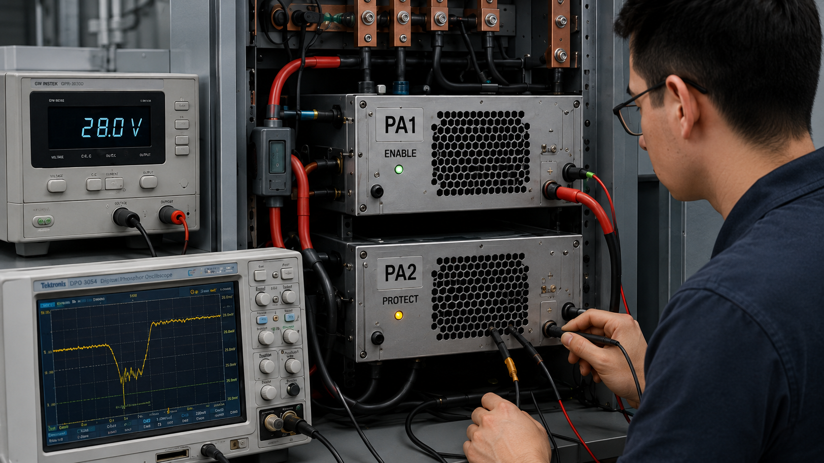
A multi-PA cabinet can show the expected DC voltage at the source and still develop a shared DC bus problem only when several modules use the same distribution path. The overlooked question is not simply whether the source has enough total watts, but what each PA actually sees when another load changes current.
If PA2 alarms when PA1 enables, PA2 may appear faulty. But if the symptom follows a branch, cabinet slot, or multi-channel load condition rather than the module S/N, replacing the amplifier may not solve the problem.
Before blaming the affected PA, the buyer needs to answer one question: what measurements show whether the disturbance originates inside the module or is being transferred through the shared DC bus and return path?
1. What Does a Shared DC Bus Actually Include?
A shared DC bus is the power-delivery network used by two or more PA modules or related cabinet loads.
The relevant path may include:
- Battery, alternator, external source, or DC-DC converter
- Main positive distribution path
- Fuse, relay, contactor, or protection device
- Distribution block or busbar
- Branch wiring and connectors
- PA positive input
- Designated DC return conductors
- Shared return connection back to the source
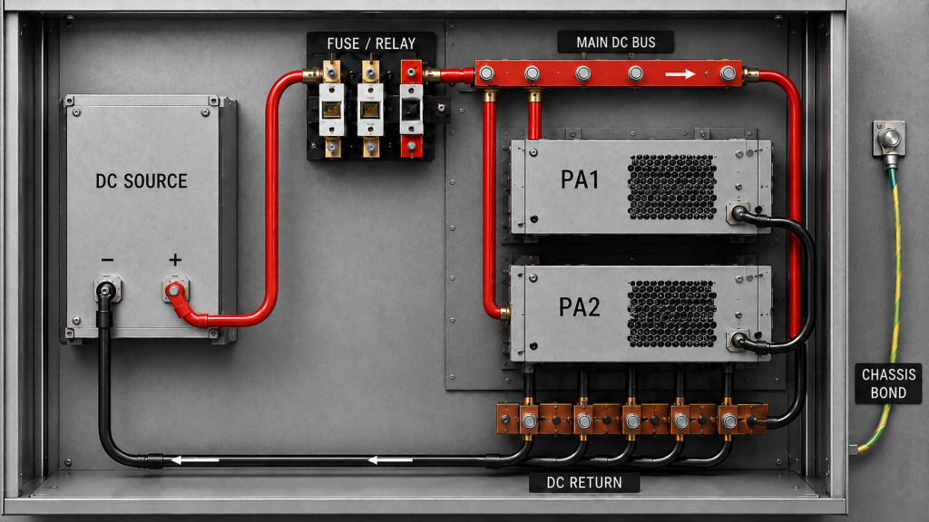
Every conductor, connector, fuse, relay, busbar, and return path has some impedance. When current changes, that impedance can create a voltage change elsewhere in the network.
A shared DC bus should therefore be defined around the intended power-delivery and DC-return paths.
Chassis bonds, signal references, RF shields, and communication grounds may interact with the same electrical system, but they should not automatically be treated as the same node or as normal PA return conductors.
The first step is to map the actual power path from the source to each PA input and back through the intended DC return.
Do not stop at the voltage shown on the power supply.
The engineering question is:
What electrical condition does each PA see at its own terminals when the rest of the cabinet changes state?
2. Which Load Transitions Actually Stress a Shared DC Bus?
RF PA current draw is not one fixed number.
The bus can change significantly when a module is:
- Enabling
- Entering RF transmit
- Changing RF output
- Operating continuously or intermittently
- Recovering from protection
- Operating while neighboring PAs also draw current
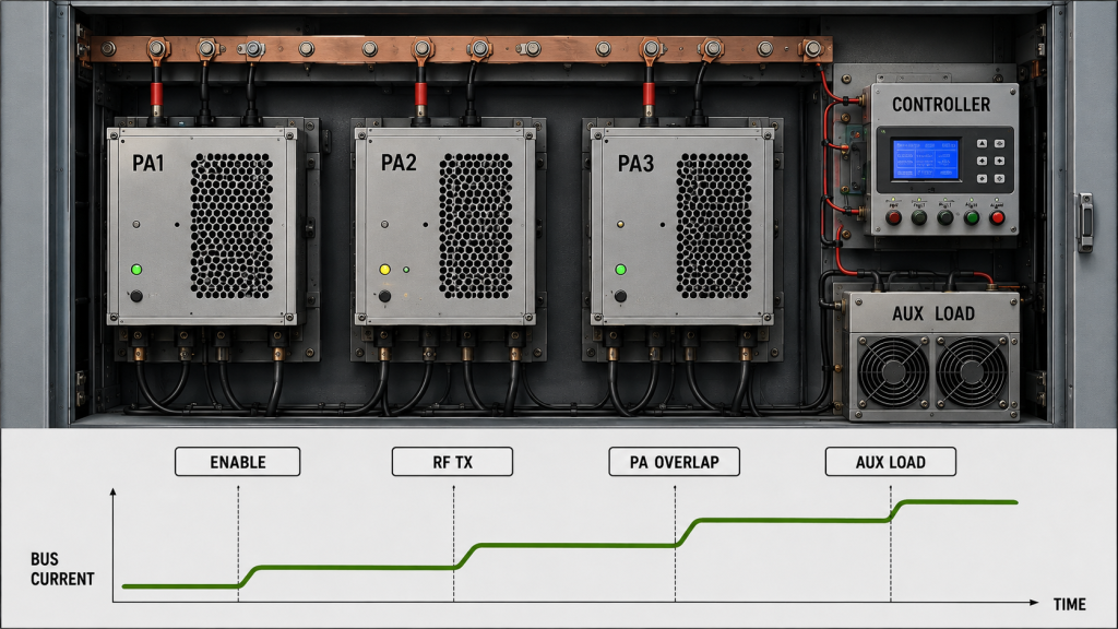
Other loads such as fans, controllers, SDRs, active RF devices, and DC-DC converters can also affect the bus.
For shared-bus diagnosis, the most useful question is:
Which load transition occurred immediately before the affected voltage, alarm, reset, or RF-output change?
Useful events to isolate include:
- One PA enabling
- Several PAs enabling simultaneously
- A large RF output transition
- Duty-cycle overlap
- An auxiliary load starting
- A protection or recovery event
- A vehicle-state change
Continuous current and transient current should not be treated as the same requirement.
A cabinet may support the sustained current of several modules but still experience a short disturbance when they enable together. A harmless startup event also does not prove that the distribution path can support the required continuous load.
Record the relevant event duration or measurement window.
If the broader problem is general PA output reduction caused by the DC power chain rather than cross-load interaction, use the separate RF PA DC power troubleshooting review.
This page focuses on what changes because several loads share the same distribution network.
3. How to Measure Shared-Bus Sag and Transients at the PA Input
A DC source can appear normal while the affected PA sees a different voltage.
That is why one reading at the power supply is not enough.
Useful measurement points include:
- Source or DC-DC converter output
- Main cabinet distribution node
- Affected PA input terminals
- Triggering PA input or branch
- Relevant DC return points
The most important measurement is usually the voltage at the PA terminals during the event.
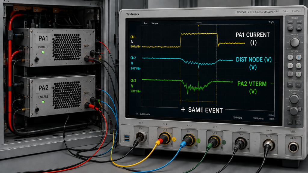
A source reading taken before the load step, or a PA reading taken after recovery, cannot show what happened during the disturbance.
Correlate Current and Voltage on the Same Time Basis
Record the triggering current step and the affected PA-terminal voltage on the same time basis.
For short transients, capture the triggering current together with the critical source, distribution-node, and PA-terminal voltages on a common time basis wherever practical.
For example:
- PA1 enables
- PA1 current rises
- Shared distribution voltage changes
- PA2 terminal voltage changes
- PA2 reports an alarm or RF-output change
Measurements from separate operating events may still help with screening, but they are weaker evidence for proving the propagation path of one specific disturbance.
Distinguish Sustained Sag From Short Transients
A shared bus can experience:
- Sustained voltage drop
- Short startup sag
- Converter recovery
- Relay or switching transients
- Load-dependent ripple
- Repetitive duty-cycle disturbances
A transient record is useful only when the measurement point, amplitude, duration, operating sequence, load state, triggering event, and relevant recovery behavior are known.
An average 28 V reading cannot describe a short load-step disturbance.
Separate Sustained Voltage Acceptance From Transient Acceptance
Do not use one voltage number to represent every DC-bus condition.
For sustained or quasi-steady operation, define the minimum qualified PA-terminal voltage under the approved load condition.
For short load-step events, define a separate transient envelope that may include:
- Permitted voltage excursion
- Event duration
- Recovery criterion
- Triggering load condition
- Approved operating state
The transient boundary should come from the qualified module or system requirement, not an arbitrary percentage of nominal source voltage.
A short excursion and a sustained undervoltage condition are not automatically equivalent.
The same principle applies when reviewing 28 V RF PA voltage margin: source voltage, distribution voltage, and PA-terminal voltage are different measurement points.
4. How Can a Shared Return Path Make One Load Affect Another?
Shared-bus interaction does not occur only on the positive supply path.
A changing PA current can create a voltage difference across shared return impedance, which may alter the reference seen by another circuit if the relevant current paths overlap.
The sequence can look like this:
PA current step → shared return voltage change → local reference shift → another circuit sees a different electrical condition
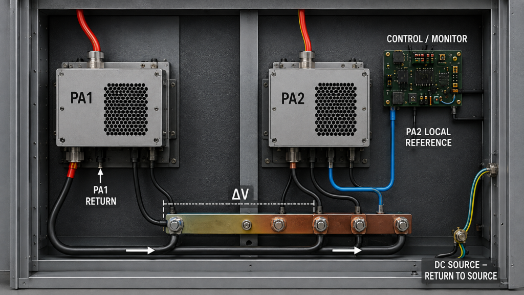
Possible symptoms include:
- Controller reset
- Protection indication
- Communication disturbance
- Measurement inconsistency
- Apparent PA fault
- RF-output change
This does not mean that every alarm is a grounding problem.
The return path becomes relevant when a symptom appears only under particular shared-load combinations.
Useful checks include:
- Which loads share the same return conductor?
- Where do branch returns join?
- Is PA current flowing through a path also used as a sensitive reference?
- Does the symptom follow a branch or cabinet position?
- Does changing the load combination change the symptom?
- Are chassis and signal-reference connections being confused with the intended PA DC return?
The complete grounding architecture—including DC return, chassis bond, RF shield, signal reference, and instrument ground—belongs in the RF PA grounding guide.
Here, the narrower question is whether overlapping return impedance allows one load transition to alter the electrical condition seen by another device.
5. How to Separate a PA Fault From Shared-Bus Interaction
Do not change several variables immediately after the first alarm.
Before changing cable paths, branch assignments, grounding, enable timing, protection settings, or module position, record the baseline condition.
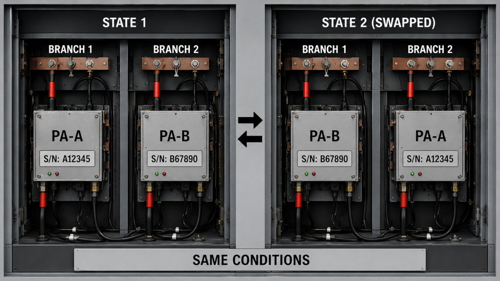
When comparing module, branch, or load-combination behavior, keep these conditions consistent unless one is intentionally being tested:
- Source or vehicle state
- RF operating point
- RF load or VSWR condition
- Enable sequence
- Relevant cooling state
- Measurement points
- Protection configuration
- Other major cabinet loads
A practical diagnostic sequence is:
- Record the affected PA S/N and cabinet slot.
- Record source voltage and affected PA-terminal voltage.
- Record total cabinet current and relevant per-PA current.
- Identify which load transition occurs before the symptom.
- Record simultaneous or staggered enable state.
- Record protection or alarm status.
- Record RF output if the symptom includes RF-performance change.
- Repeat the affected PA alone under the same controlled boundaries.
- Repeat the intended multi-load operating combination.
- If practical, exchange modules or branches while keeping the other test boundaries unchanged.
- Compare whether the symptom follows the module, branch, slot, or load combination.
Fault Pattern Table
| Observed Pattern | What It Suggests | Next Measurement |
|---|---|---|
| The same PA shows the problem in different branches | Module-specific behavior becomes more likely | Compare terminal voltage, current, protection status, and RF output under controlled conditions |
| Different PAs show the problem on the same branch or slot | Branch or distribution-path behavior becomes more likely | Measure branch voltage drop, connector path, protection devices, and return path |
| The problem appears only when another PA enables | Shared-bus interaction becomes credible | Correlate triggering current with affected PA-terminal voltage and alarm timing |
| The problem appears only during a particular multi-PA combination | Load-combination interaction becomes credible | Reproduce the exact operating sequence and compare per-PA current and bus voltage |
| Source voltage remains normal but PA-terminal voltage changes | Local distribution impedance becomes more likely | Compare source, distribution-node, and PA-terminal voltage during the same event |
| Alarm timing matches a return-path disturbance | Shared-reference or return interaction becomes possible | Compare intended DC return, chassis bond, and sensitive reference paths |
These patterns are diagnostic clues, not final proof.
A branch-related symptom does not automatically identify the connector, fuse, cable, relay, or return path as the root cause. Likewise, a load-combination-specific fault does not prove that the PA modules themselves are healthy.
The purpose is to determine where the investigation should continue.
6. What Evidence Proves Shared DC Bus Interaction?
A screenshot of “28.0 V” is weak evidence.
A useful diagnosis should connect the electrical state, load condition, affected module, and event timing so the disturbance can be reconstructed.
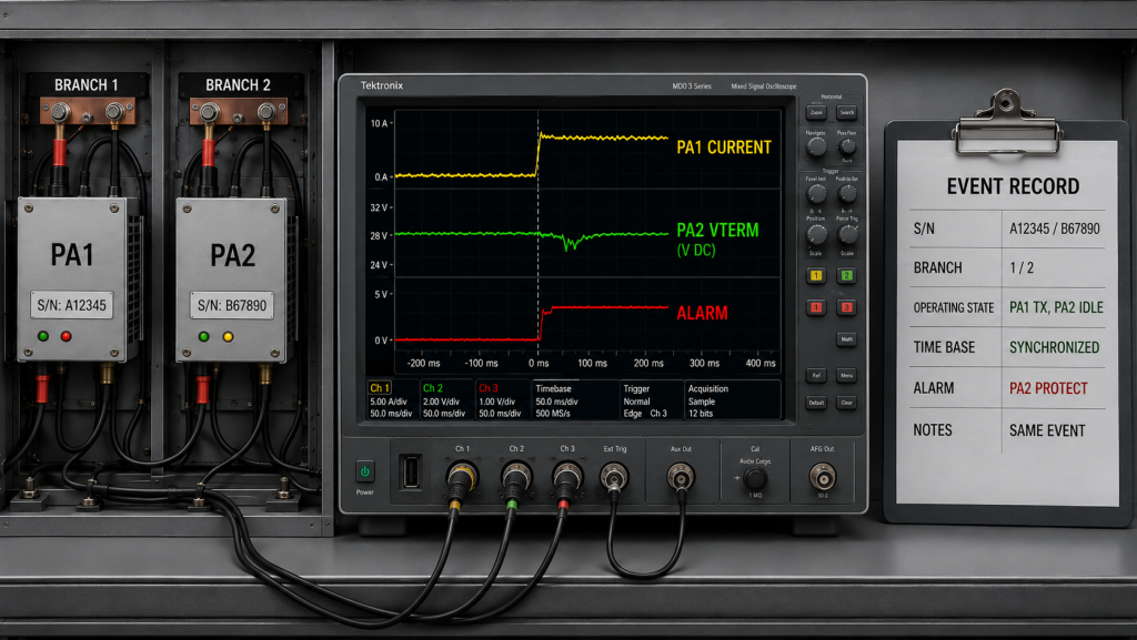
Record as appropriate:
- Source or converter voltage
- Main distribution-node voltage
- Affected PA-terminal voltage
- Per-PA and total cabinet current
- Continuous versus transient current condition
- Module S/N
- Cabinet slot or branch
- Simultaneous or staggered enable state
- RF operating state and duty cycle
- RF output if relevant
- Protection or alarm status
- Triggering event
- Ripple or transient measurement point
- Event amplitude and duration
- Recovery behavior where relevant
- Vehicle operating state
- DC return configuration
- Relevant grounding or reference condition
- Test timestamp or synchronized event record
For short transients, the strongest evidence captures the triggering current and relevant voltages on a common time basis.
Vehicle-state testing matters only where the real system is expected to operate under more than one source condition, such as engine running, idle, battery-only, or external-source operation.
Only required deployment states should become acceptance boundaries.
Shared DC Bus Evidence Table
| Acceptance Question | Weak Evidence | Better Evidence | What the Better Evidence Can Show |
|---|---|---|---|
| Did the source remain stable? | One source-voltage reading | Source voltage captured during the load event | Whether the upstream source changed during the disturbance |
| What did the affected PA actually see? | Nominal 28 V specification | PA-terminal voltage captured during the event | Whether local distribution behavior changed the module input condition |
| Did another load trigger the event? | Separate current and alarm records | Synchronized triggering-current and affected-voltage/alarm record | Whether the events are correlated |
| Does the fault follow the module? | One failed test | S/N and branch comparison under controlled conditions | Whether behavior is more likely module-specific or installation-specific |
| Is the issue tied to one branch? | Cabinet-level voltage only | Branch voltage, connector path, and return-path comparison | Whether local distribution impedance is involved |
| Is a transient involved? | Average multimeter reading | Time-resolved record with measurement point, excursion, duration, and recovery | Whether a short disturbance is hidden by the average value |
| Can the result be accepted? | “No reset observed” | Defined sustained-voltage boundary, transient envelope, protection limits, and approved operating combination | Whether the tested condition meets the agreed requirement |
| Can the test be repeated later? | Unidentified screenshot | S/N-linked test record with configuration and operating sequence | Whether production or service teams can reproduce the condition |
Evidence should define both what was measured and what constitutes an acceptable result.
That may include:
- Minimum sustained PA-terminal voltage
- Permitted transient excursion
- Transient duration or recovery criterion
- Permitted protection behavior
- Required RF performance during the event
- Operating combination covered by the test
- Whether simultaneous enable is allowed
- Whether a defined vehicle state is part of acceptance
“No shutdown” is not automatically the same as sufficient electrical margin.
When shared-bus behavior affects module selection or approval, define the sustained PA-terminal voltage boundary, transient current and voltage conditions, simultaneous-load state, protection behavior, and required test evidence before selecting custom RF power amplifier modules.
7. What Should the RFQ Define for Shared DC Bus Approval?
Terms such as “28 V system,” “enough current,” “stable power,” or “staggered startup” are not complete acceptance requirements.
The RFQ should define the electrical event and the pass boundary used by both buyer and supplier.
Shared DC Bus RFQ Checklist
| RFQ Item | What to Define | Why It Matters | Expected Evidence |
|---|---|---|---|
| DC source range | Required source or converter operating range | Defines the upstream supply condition | Source-voltage record |
| PA count and operating combination | Which PAs can operate simultaneously | Defines the real shared load | Multi-PA operating record |
| Per-PA current | Continuous and relevant transient current demand | Separates sustained load from short load events | Per-PA current record |
| Total cabinet current | Expected combined operating condition | Defines overall bus loading | Total-current record |
| Sustained PA-terminal voltage | Minimum qualified PA-terminal voltage under the defined sustained load | Confirms that distribution loss does not move the PA outside its approved operating boundary | Terminal-voltage record under the defined load |
| Transient voltage behavior | Permitted voltage excursion plus event duration or recovery criterion | Separates short transient behavior from sustained undervoltage | Time-resolved voltage and triggering-current record |
| Enable sequence | Whether simultaneous enable is allowed or sequencing is guaranteed | Defines startup interaction | Enable timing and current record |
| Distribution path | Busbar, branch cable, fuse, relay, connector, and protection path | Identifies common and local impedance | Distribution drawing or test record |
| DC return path | Intended PA return and branch-return topology | Defines possible shared-return interaction | Return-path drawing |
| Ripple / repetitive disturbance | Measurement point, operating state, and permitted boundary | Makes repetitive disturbance acceptance measurable | Time-resolved test record |
| Vehicle state | Required engine-running, idle, battery-only, or external-source condition | Prevents one source state from being treated as universal | State-specific test record |
| Protection behavior | Allowed alarm, reset, derating, or recovery condition | Defines what counts as a pass | Logged protection status |
| Traceability | S/N, slot, branch, and test configuration | Allows reproduction and later service diagnosis | S/N-linked report |
Do Not Use Staggered Enable to Hide an Unaccepted Condition
Staggered enable can reduce the magnitude of a combined current step.
But it is an approved mitigation only when the real control architecture guarantees that sequence in every accepted operating state.
If simultaneous enable is permitted, the shared bus must still be verified under that condition.
Where the sequence is controller-defined, verify the AT command timing and enable sequence separately from the DC-bus pass/fail result.
Otherwise, a laboratory test can pass only because the sequence removed a load event that may still occur in the deployed system.
Define the Electrical Condition at the PA, Not Only at the Source
A requirement such as:
“28 VDC input”
does not define what the PA must receive during the worst accepted operating combination.
A stronger requirement defines:
- Source operating range
- Distribution condition
- Simultaneous-load state
- Minimum sustained PA-terminal voltage
- Permitted transient envelope
- Measurement point
- Event duration or recovery criterion where relevant
- Pass/fail boundary
That turns “the power supply is large enough” into a condition that can actually be verified.
FAQ
Can several RF PA modules share one 28 V DC bus?
Yes, provided the distribution network is verified for the required simultaneous load, sustained and transient current, PA-terminal voltage, return-path condition, and protection behavior.
Enough nominal source power does not by itself prove that every PA sees an acceptable electrical condition when other loads change state.
Why can one PA alarm when another PA turns on?
When one PA enables, its current step can create a voltage change across shared distribution or return impedance.
Another PA may then see a temporary terminal-voltage or reference change even though it did not initiate the disturbance.
To test this, correlate the triggering PA current with the affected PA-terminal voltage, alarm timing, branch, and module S/N while keeping the other relevant boundaries controlled.
What evidence proves a shared DC bus problem?
The strongest evidence is repeatable correlation between a defined load event and a disturbance that follows the shared distribution path, branch, slot, or operating combination rather than the affected module alone.
Useful evidence includes synchronized current and voltage measurements, PA-terminal voltage, S/N and branch traceability, protection logs, transient timing, and defined sustained and transient pass criteria.
Conclusion
A shared DC bus interaction becomes credible when a voltage change, reset, alarm, or RF-performance disturbance tracks a branch, slot, load combination, or synchronized current event rather than the affected PA S/N under otherwise controlled conditions.
Diagnosis should begin by measuring what the PA actually sees at its terminals while another load changes state, then determining whether the symptom follows the module, branch, or operating combination.
Acceptance should separately define the sustained PA-terminal voltage boundary and the transient voltage envelope, together with current demand, enable logic, return path, protection behavior, and the exact operating combination covered by the test.
A result obtained under staggered enable, a different vehicle state, or a changed branch assignment should not be extended to an operating condition that the deployed system still permits but the test did not reproduce.
For an RFQ review, contact RF SKYPOWER with your vehicle DC voltage range, PA count and output targets, simultaneous-enable logic, per-PA sustained and transient current requirements, DC-DC and distribution topology, branch cable/fuse/relay details, return-path architecture, minimum sustained PA-terminal voltage, permitted transient envelope, RF load or VSWR boundary, protection requirements, and required S/N-linked test evidence.