


28V RF power amplifiers should be chosen only after you confirm that the power system can hold enough voltage margin under real full-load conditions. A supply label that says 28V does not prove that the amplifier input still sees stable 28V after current demand, cable drop, terminal resistance, relay paths, DC distribution boards, and multi-module operation are added.
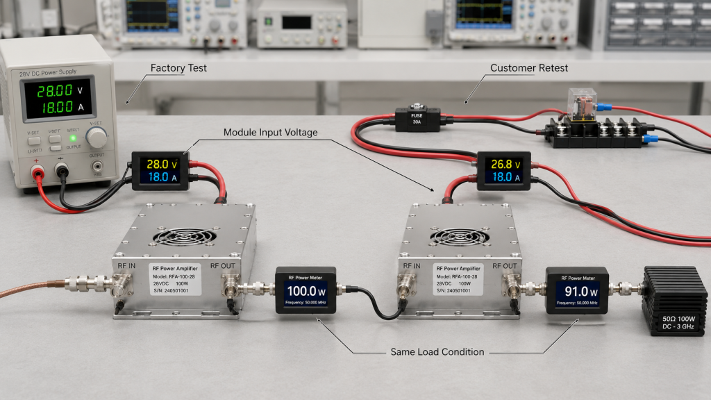
For a system integrator, the practical risk is simple: the amplifier may pass a factory test on a stable bench supply, then show lower output, voltage alarms, control instability, or inconsistent retest data after installation. That does not always mean the RF module is weak. It may mean the DC input condition was never defined as part of the selection process.
A professional RF Power Amplifier Supply Voltage review should connect frequency band, output power, full-load current, duty cycle, wiring path, power quality, thermal condition, and protection behavior before approval. Before you treat 28V supply as a wiring detail, it should be reviewed as part of module selection before final wiring, especially in C-UAS platforms where multiple RF channels may share the same power architecture.
1. Why Is 28V Supply Voltage a Selection Condition?
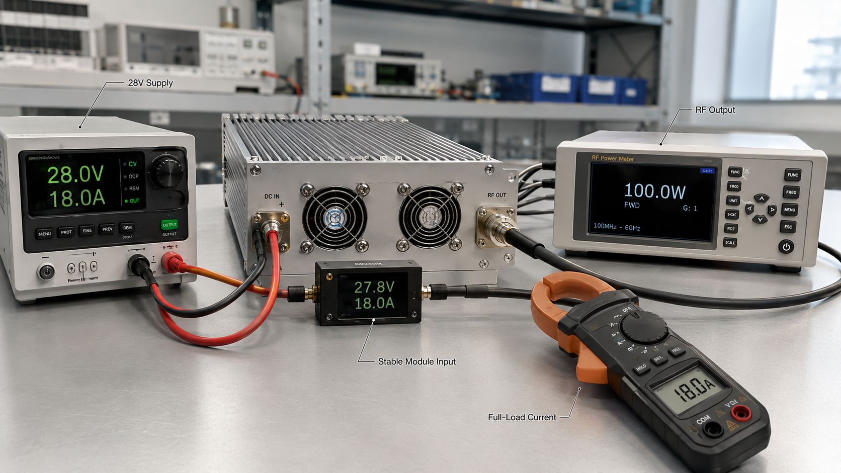
28V supply voltage is a selection condition because an RF Power Amplifier Supply Voltage rating only matters when the module can receive stable input power under the actual operating load. If you choose the amplifier first and check the power system later, you may approve a module that cannot sustain its rated output inside your cabinet, vehicle, fixed site, or multi-channel platform.
Here’s the engineering point: a power supply display may show 28V at the source, while the module input sees a lower voltage after current flows through the full DC path. That path may include cables, connectors, fuses, relays, control boards, and a DC bus shared by other loads.
What must be checked before approval?
You should check 28V supply voltage before final approval because the amplifier is a dynamic load, not a simple control board. Its current demand changes with output power, duty cycle, frequency range, and operating mode.
Key items include:
- Module input voltage range
- Recommended operating voltage
- Full-load current demand
- Cable and terminal voltage drop
- DC bus sharing with other channels
- Under-voltage and over-voltage thresholds
How does this affect system risk?
A stable laboratory result does not prove stable field behavior if the DC input condition changes. The risk becomes worse when the amplifier is installed far from the power source or connected through multiple distribution points.
Key Takeaway: Treating 28V supply as a selection condition helps you avoid approving an amplifier based on a power number that your real system cannot support.
| Selection item | Why it matters | Field risk if ignored |
|---|---|---|
| Module input voltage | Confirms the real voltage at the amplifier | Output drop |
| Full-load current | Shows actual power demand | Supply overload |
| DC path loss | Captures cable and terminal drop | Hidden under-voltage |
| Protection threshold | Defines safe operating limits | Repeated alarms |
This table shows why voltage review belongs in the selection stage, not after the cabinet is already wired.
2. How to Prevent Output Drops in RF Power Amplifiers
A 28V supply that looks stable can still fail an RF Power Amplifier Supply Voltage requirement if the module input drops during full-load output. The key difference is between static voltage and loaded voltage.
Here’s the field reality: many teams check the power supply screen, see 28V, and assume the amplifier is properly powered. But the amplifier does not operate from the screen value; it operates from the voltage available at its own input terminals while current is flowing.
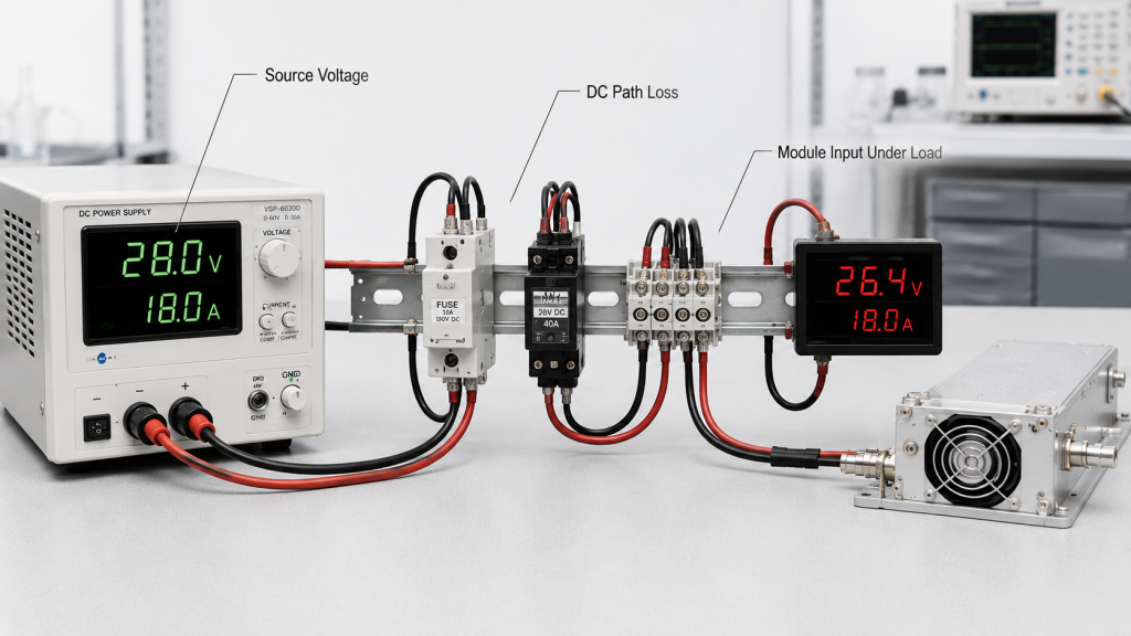
Where does the voltage drop come from?
Voltage drop often comes from normal system components that were not treated as part of the power chain. Each item may look small alone, but the combined effect becomes visible at high current.
Common sources include:
- Long DC cables
- Undersized wiring
- Fuse holders
- Relay contacts
- Terminal blocks
- DC distribution boards
- Aging connectors
How should engineers diagnose the issue?
If the RF output falls during full-load testing, the first step is not blaming the amplifier but learning how to check the power chain under real load. Measure voltage at the module input during standby, low power, full power, and simultaneous channel operation.
Key Takeaway: Loaded voltage tells you what the amplifier actually receives; source voltage only tells you what the power supply intends to deliver.
| Test point | What it tells you | Best use |
|---|---|---|
| Power supply output | Source condition | Basic setup check |
| DC bus input | Distribution condition | Cabinet-level review |
| Module input | Real amplifier condition | Full-load validation |
| During RF output | Dynamic voltage behavior | Acceptance testing |
This comparison helps you avoid confusing a healthy power supply with a healthy power path.
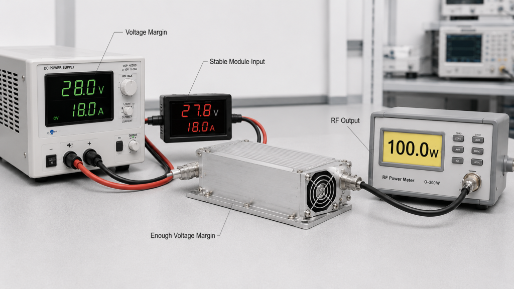
3. What Voltage Margin Means for RF Power Amplifiers
Voltage margin supports full RF output because an RF Power Amplifier Supply Voltage condition directly affects how much usable RF power the module can sustain. RF output power is converted from DC input energy, so a weak DC input path can limit the amplifier even when the selected RF power rating looks correct.
This is where system integrators should pay attention: selecting a 100W or 200W module does not guarantee antenna-side performance if the DC input collapses under load. DC supply margin and RF output margin must be reviewed together.
Why is DC margin different from RF margin?
DC margin is the power-side headroom that lets the amplifier receive stable voltage and current. RF margin is the output-side headroom that accounts for cable loss, antenna mismatch, heat, and real deployment loss.
You should separate the two:
- DC margin supports the amplifier input
- RF margin supports the usable output target
- Both are needed for stable field performance
- Neither one replaces the other
How does frequency range affect current demand?
Different frequency bands and module designs can have different efficiency and current behavior. After you match the operating band before power approval, the next question is whether the 28V system can support the required current across that band.
When voltage is unstable, it becomes harder to compare full-band gain behavior, especially near band edges where output variation may already be more visible.
Key Takeaway: Voltage margin protects the practical value of your selected RF power rating by helping the module hold output under real operating stress.
| Margin type | Side of system | Main question |
|---|---|---|
| Voltage margin | DC input | Can the module receive stable power? |
| Current margin | DC input | Can the supply support full load? |
| Power margin | RF output | Is there enough usable output after loss? |
| Thermal margin | System environment | Can output be sustained over time? |
This table keeps the approval discussion clear: the DC side and RF side are connected, but they are not the same problem.
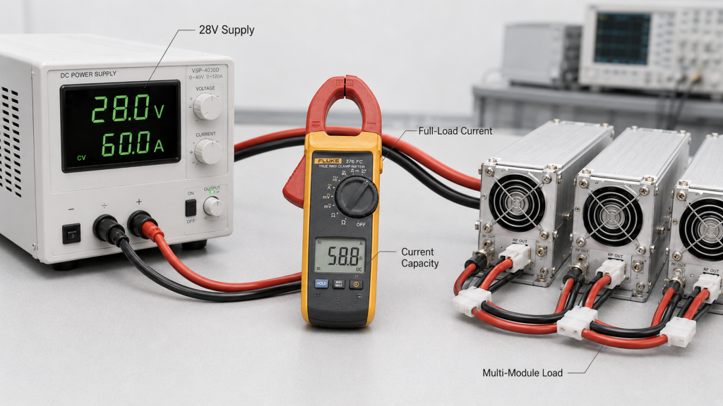
4. How to Size Current Capacity for RF Power Amplifiers?
Current capacity must be checked with 28V because an RF Power Amplifier Supply Voltage label does not prove that the supply can deliver the current required for full-load output. A 28V source with weak current capacity may still sag, heat up, trigger protection, or limit amplifier performance.
The practical risk is clear: voltage without current is not a complete power condition. In multi-channel systems, the total current demand can rise quickly when several modules operate together.
What current data should you request?
Before approving a module, ask for current demand under the conditions closest to your real use case. A single low-duty test point may not represent long-duty or simultaneous operation.
Useful data includes:
- Current at target output power
- Current at low, middle, and high band points
- Current during continuous operation
- Current during startup or enable sequence
- Current for simultaneous module operation
Why is power supply rating not enough?
A power supply rating may be measured under ideal cooling and load conditions. If it runs near its maximum rating for long periods, voltage stability and service life may suffer.
Key Takeaway: Checking current capacity prevents you from choosing a 28V supply that is correct on voltage but too weak for the amplifier’s real load profile.
| Current factor | Why it matters | What to confirm |
|---|---|---|
| Single-module load | Baseline demand | Full-output current |
| Multi-module load | Total system demand | Simultaneous current |
| Duty cycle | Average stress | Continuous capacity |
| Startup behavior | Transient load | Surge tolerance |
This table helps procurement and engineering teams ask for the right power data before the project moves into wiring and integration.
5. What Power Quality Affects RF Power Amplifiers
Ripple and transient response affect stability because an RF Power Amplifier Supply Voltage condition includes power quality, not only the average voltage number. A supply may read close to 28V while still producing ripple, noise, or short voltage dips that disturb output, control state, or protection logic.
Here’s the engineering point: high-power RF modules create changing current demand. If the power source cannot respond cleanly when the amplifier switches from standby to output, the module may see brief but important voltage movement.

What power quality items matter most?
You do not need to turn every RF buyer into a power supply designer. But you do need enough power quality information to know whether the DC source is suitable for high-current RF operation.
Check these items:
- Ripple level
- Load regulation
- Transient response
- Startup behavior
- Protection behavior
- DC bus noise from shared loads
Where can shared DC loads create problems?
A C-UAS platform may place SDR modules, control boards, fans, relays, detection units, and RF power channels on related power paths. A load change in one section can affect another if the DC architecture is not planned carefully.
Key Takeaway: Reviewing ripple and transient response helps you prevent unstable RF behavior that cannot be explained by voltage rating alone.
| Power quality factor | Possible symptom | Engineering check |
|---|---|---|
| Ripple | Output fluctuation | Measure under RF load |
| Slow response | Voltage dip at enable | Test switching states |
| Shared DC bus noise | Control instability | Separate or filter loads |
| Startup surge | Reset or alarm | Review startup sequence |
This table shows why a clean 28V number is useful, but not enough for RF power approval.
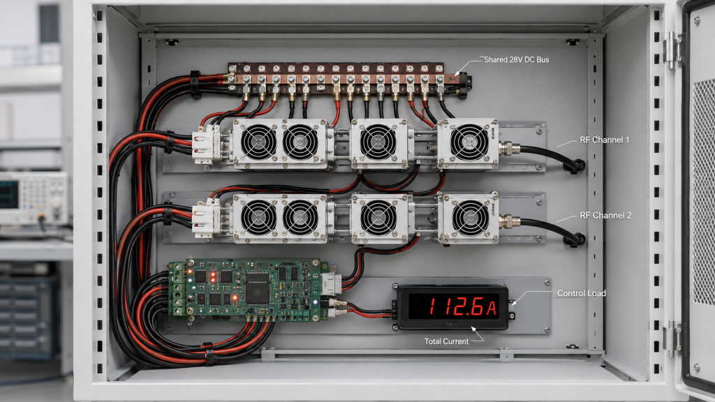
6. Why Do Multi-Channel C-UAS Systems Need More Margin?
Multi-channel C-UAS systems need more margin because an RF Power Amplifier Supply Voltage condition that works for one module may not work when several RF channels share the same DC architecture. A single-module bench test does not prove that all modules can sustain output together.
This is where system integrators should pay attention: in real C-UAS system integration, 28V supply stability must support multiple RF channels, SDR units, control boards, cooling loads, and protection logic at the same time.
What makes multi-channel loading different?
Multi-channel systems may not run every module at full output all the time. But if your mission profile allows simultaneous RF operation, the DC system must be checked against that condition.
You should define:
- Which modules can transmit together
- How long they can transmit
- Whether startup is simultaneous or sequenced
- Whether channels share one DC bus
- Whether control logic limits maximum load
How does deployment context change the risk?
For an airport perimeter deployment, supply voltage is part of system reliability because RF channels must remain predictable during long-duty operation. A channel that drops output under shared load can weaken the whole RF chain, even if the individual amplifier is not defective.
Key Takeaway: Multi-channel planning helps you avoid approving a power supply based on single-module data that does not match the real C-UAS operating mode.
| System condition | What to check | Risk if ignored |
|---|---|---|
| Single module | Individual current | Basic mismatch |
| Multiple modules | Total current | DC bus sag |
| Shared control load | Control stability | Reset or false alarm |
| Shared cooling load | Thermal power draw | Hidden power deficit |
This table makes the selection review more realistic for platforms that operate as systems, not loose collections of modules.
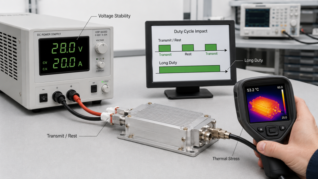
7. How Does Duty Cycle Change Voltage Requirements?
Duty cycle changes voltage requirements because an RF Power Amplifier Supply Voltage condition must support the amplifier for the actual transmit rhythm, not only a short test burst. Short output, intermittent output, and long-duty output create different current, heat, and voltage stability demands.
Here’s the field reality: a supply that looks acceptable during a short bench test may become unstable after long operation. Heat builds in the power source, wiring, terminals, and amplifier, and that can make voltage drop and protection behavior more visible.
What should you describe if duty cycle is unclear?
If you do not know the exact duty cycle percentage, describe the operating rhythm in practical terms. A good supplier can translate that into a more useful power review.
Share these details:
- Transmit time
- Off time
- Single run duration
- Daily operating pattern
- Continuous or intermittent operation
- Ambient temperature
- Cooling method
Why does long-duty output expose weak power design?
Long-duty output keeps current demand active for longer periods. That sustained load can warm cables, terminals, and power supplies, increasing resistance and reducing voltage stability.
Key Takeaway: Defining duty cycle helps you select a power system based on real operating stress instead of a short, clean, low-risk test condition.
| Duty profile | Power system stress | Selection concern |
|---|---|---|
| Short burst | Transient demand | Startup and response |
| Intermittent output | Repeated loading | Recovery and heating |
| Long-duty output | Sustained current | Continuous capacity |
| Multi-channel duty | Combined loading | Total DC margin |
This table helps you turn vague operating expectations into power conditions that can be reviewed before approval.
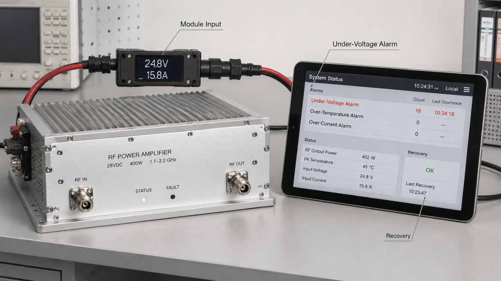
8. What Protection Alarms Mean for RF Power Amplifiers
Voltage protection should match field conditions because an RF Power Amplifier Supply Voltage limit is meant to protect the module from abnormal power, not act as a normal operating state. If the system runs too close to under-voltage or over-voltage thresholds, protection may appear repeatedly during real operation.
The practical risk is clear: protection alarms are not always module failures. They may be evidence that the power system, DC path, or operating mode is pushing the amplifier outside a stable input range.
What protection states should be monitored?
A good system should not only turn RF output on and off. It should also understand why output changes, especially when alarms appear.
Relevant states include:
- Under-voltage alarm
- Over-voltage alarm
- Temperature alarm
- VSWR or reflected power alarm
- Enable status
- Recovery condition
How should the controller use alarm feedback?
When voltage protection appears in the field, the controller should read protection and alarm status instead of treating reduced output as an unknown module failure. This makes troubleshooting faster and reduces unnecessary returns.
Key Takeaway: Matching protection thresholds with real field voltage behavior helps the system protect hardware without turning normal operation into repeated alarm recovery.
| Protection item | What it prevents | What to verify |
|---|---|---|
| Under-voltage | Weak or unstable operation | Worst-case voltage stays above limit |
| Over-voltage | Device stress or damage | Source stays within safe range |
| Temperature alarm | Heat damage | Cooling supports duty cycle |
| VSWR alarm | Reflected-power stress | Load path remains matched |
This table shows why voltage protection should be reviewed with the whole system, not only the amplifier datasheet.
9. How Should Factory Voltage and Customer Voltage Compare?
Factory voltage and customer voltage should compare under the same RF Power Amplifier Supply Voltage measurement point, load condition, current demand, and test duration. If these conditions differ, the output data may not be fairly comparable.
Here’s the engineering point: a factory may test the module with a stable supply, short DC path, controlled load, and known ambient temperature. A customer may retest through a long wiring path, shared DC bus, cabinet terminals, and different duty cycle.
What should a useful test report record?
A useful test report should make the DC input condition visible, not hidden. Without that information, it is difficult to separate module behavior from system power behavior.
Record these items:
- Power supply setting
- Voltage at module input
- Full-load current
- Measurement point
- Test duration
- Duty cycle
- Load condition
- Ambient temperature
- Protection status
Why does this matter for wideband testing?
To verify wideband performance with test evidence, the report should record not only frequency and output power, but also supply voltage, current, load condition, and test duration. Otherwise, a band-edge output change may be blamed on RF design when unstable DC input is part of the cause.
Key Takeaway: Matching factory and customer voltage conditions makes retesting more useful, reduces argument, and helps engineers identify the real cause of output differences.
| Test variable | Factory test | Customer retest |
|---|---|---|
| Voltage point | Module input preferred | Module input required |
| DC path | Short and controlled | Real system wiring |
| Load condition | Defined RF load | Same or documented equivalent |
| Duration | Recorded | Matched or explained |
This table helps both sides compare results based on shared conditions instead of assumptions.
10. How to Confirm 28V Margin for RF Power Amplifiers
You can confirm 28V margin before approval by reviewing RF Power Amplifier Supply Voltage, full-load current, duty cycle, DC path loss, power quality, protection thresholds, and multi-module operation as one approval package. The goal is not to overcomplicate procurement; the goal is to prevent preventable integration failures.
This is where a source-factory engineering review can help. RF SKYPOWER supports RF power amplifier module selection by reviewing frequency band, target output power, current demand, duty cycle, supply condition, thermal load, protection behavior, and C-UAS integration scenario before final confirmation.
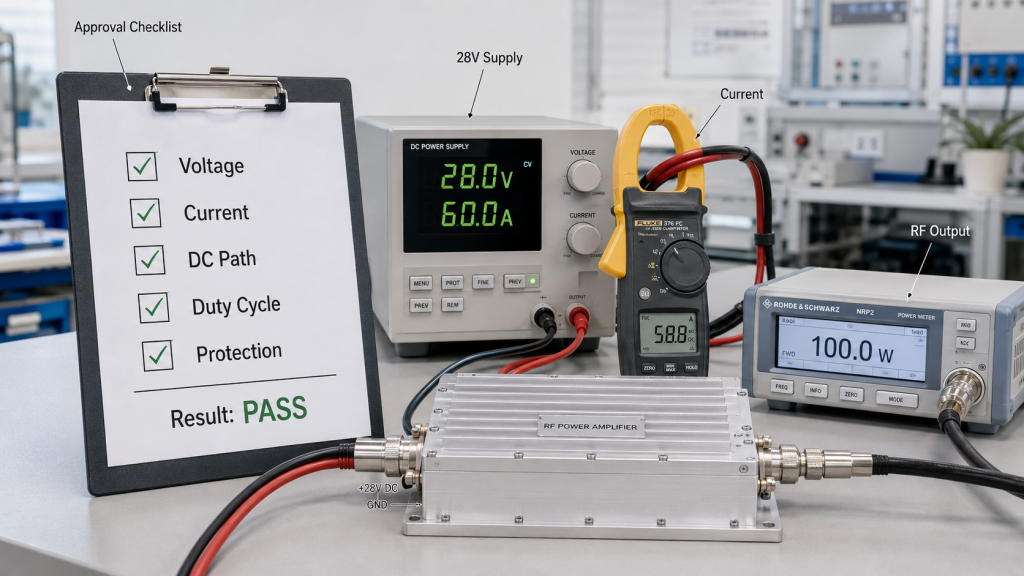
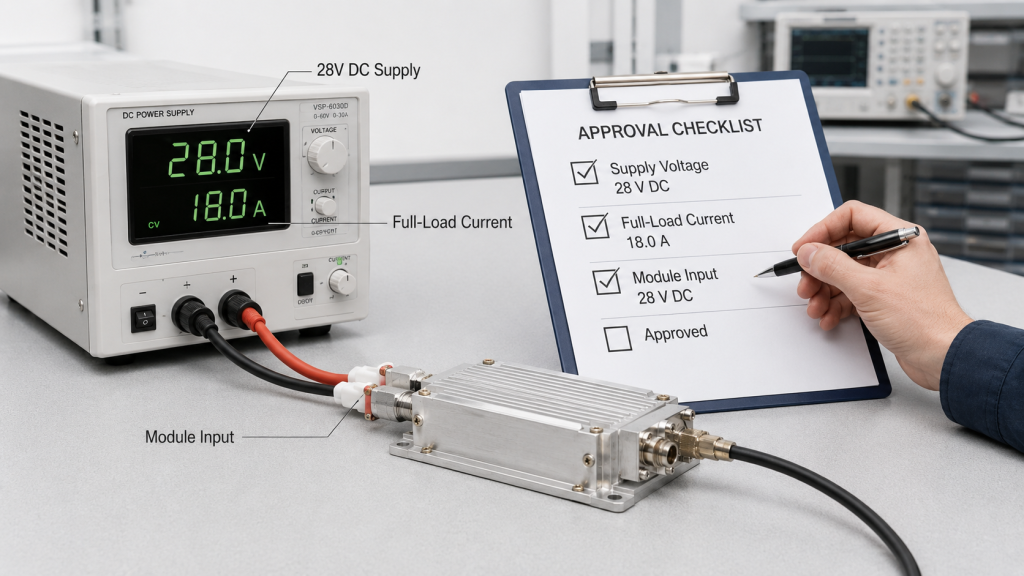
What should be in the approval checklist?
Your approval checklist should be practical enough for RF engineers, system integrators, and procurement reviewers to use together. It should connect the module datasheet with the real power architecture.
Include these items:
- Input voltage range
- Recommended 28V operating point
- Full-load current
- Power supply capacity
- Module input voltage under load
- Cable and terminal path
- Duty cycle and run time
- Simultaneous channel operation
- Ripple and transient response
- Test report power conditions
What decision does the checklist support?
The checklist helps you decide whether the amplifier, power supply, wiring path, control logic, and operating profile are aligned. If one item is weak, you can fix it before the system is already assembled.
Key Takeaway: Confirming 28V margin before approval reduces retest confusion, system rework, protection alarms, and field output instability.
| Approval area | Question to answer | Pass condition |
|---|---|---|
| Voltage | Is module input stable under load? | Within safe range |
| Current | Can supply support full demand? | Adequate margin |
| DC path | Does wiring create hidden drop? | Drop is measured and acceptable |
| Operation | Does duty cycle match power design? | Continuous needs are covered |
| Protection | Are alarm limits understood? | No routine threshold operation |
This table gives you a practical approval frame: do not approve the amplifier alone; approve the amplifier inside its real power system.
FAQ
Can I use any 28V supply for a 28V RF power amplifier?
No, you should not assume any 28V supply is suitable. The supply must provide stable module input voltage, enough current, acceptable ripple, proper transient response, and safe behavior under your real duty cycle.
How do I know if voltage drop is causing low output?
Measure voltage at the amplifier input during full RF output. If the power supply display stays near 28V but the module input falls under load, the DC path or supply capacity may be limiting output.
What’s the best way to size current capacity?
The best way is to start from the amplifier’s full-load current under your target frequency, output power, and duty cycle. Then add margin for simultaneous modules, startup behavior, cable loss, and long-duty thermal stress.
Can voltage protection be ignored if the module still works?
No, repeated voltage protection should not be treated as normal operation. It often means the power system is too close to the amplifier’s safe operating limit and should be reviewed before field deployment.
How do I compare factory test results with my own retest?
Compare the same measurement point, load condition, duty cycle, test duration, and module input voltage. If your DC path is different from the factory setup, document the difference before judging amplifier performance.
Conclusion
28V RF power amplifier selection should not stop at frequency range and target wattage. This article showed why supply voltage must be checked as a full-load system condition, how voltage drop hides inside the DC path, why current capacity and power quality matter, how duty cycle changes supply stress, and why protection alarms should be interpreted with real field voltage data.
For system integrators, RF engineers, and procurement reviewers, the practical lesson is clear: do not only ask whether the module accepts 28V input. Ask whether your complete system can keep enough 28V supply margin at the module input under full-load output, worst-case duty cycle, real DC wiring, and simultaneous RF channel operation.
RF SKYPOWER can help review frequency band, target output power, full-load current, 28V supply voltage, duty cycle, DC path loss, thermal condition, voltage protection status, and C-UAS integration scenario before final approval. If your project has not confirmed these power conditions yet, you can discuss your 28V supply conditions with our engineering team before committing to the final module configuration.
Stable RF output starts before RF testing; it starts with a power system that can prove the amplifier will receive what the mission expects it to deliver.