










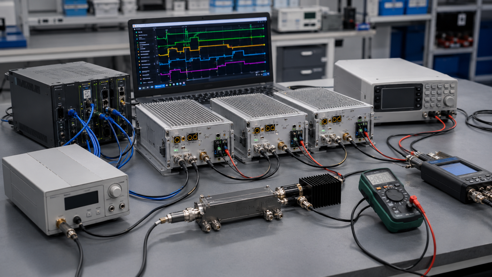
RF PA control interface faults often look like amplifier failure. The controller sends Enable but no RF appears, an alarm remains active after the load returns to normal, status data becomes stale, one channel responds to another module’s address, or false faults appear only when RF output starts.
Replacing the amplifier before capturing the control sequence can hide the real cause. The problem may sit in active-level wiring, command timing, module addressing, latched protection, reset order, PA-terminal voltage, signal grounding, harness routing, or EMI coupling rather than in the RF output stage.
This article provides a symptom-driven troubleshooting workflow. Before replacing RF Power Amplifier Modules, record the command timeline, interface levels, alarm and status states, DC behavior, RF output, load condition, temperature, and the exact event that triggered the fault.
1. What Symptoms Point to an RF PA Control Interface Fault
A control-interface fault is a mismatch between the controller command, the PA’s reported state, and the RF behavior measured after that command.
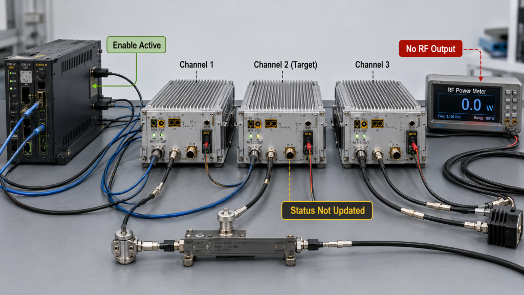
Typical symptoms include:
- Enable is active, but no RF output appears
- RF output appears only after an unexpected delay
- Alarm remains active after the original fault condition is removed
- Reset is accepted, but the PA does not recover
- Status reports Ready while no RF output is measured
- Status remains unchanged after the operating state changes
- One command affects the wrong module
- Two modules respond to the same address
- Communication works with RF off but fails after RF starts
- Repeated retries create a restart loop
- The PA works during bench testing but fails in the cabinet
- A fault appears only when several channels operate together
These symptoms do not automatically prove that the PA hardware is defective.
The same behavior may come from:
- Incorrect active-high or active-low logic
- Wrong default state during startup
- Missing or delayed Ready indication
- A latched alarm that requires a defined reset sequence
- An address or channel-mapping error
- A timeout shorter than the PA response time
- Duplicate commands or uncontrolled retries
- PA-terminal voltage drop
- Ground-reference shift
- RF coupling into the control harness
- An RF input or load condition that is not ready when Enable is asserted
The first task is to identify where the expected state sequence stops.
A typical control-state chain may include:
Command sent
→ Command accepted
→ PA enable started
→ Protection clear
→ Ready reported
→ RF output detected
→ RF output stable
Use only the states exposed by the actual interface. A discrete GPIO design may provide fewer observable steps than a digital command-and-status interface.
Before troubleshooting, compare those states with the documented RF PA control interface requirements for active levels, default states, alarm meanings, reset rules, and feedback scope.
Do not treat all available stages as one event. A controller may receive an acknowledgement before the PA is ready to generate stable RF output.
2. How to Capture the Failure Before Changing Hardware
Do not begin by replacing the PA or changing several settings at once.
Preserve the first failure state before:
- Moving the harness
- Changing controller code
- Reassigning module addresses
- Clearing the alarm
- Cycling DC power
- Changing the RF load
- Replacing the PA
- Updating firmware
- Shortening the timeout
- Increasing retry count
At minimum, record:
- Command and timestamp
- Target module or channel
- Enable level
- Available ACK and Ready state
- Alarm category
- Reset result
- PA-terminal voltage and current
- RF input and measured RF output
- Forward and reflected power
- Temperature and RF-off/RF-on condition
This is the minimum failure snapshot. Detailed interface versions, pinout revisions, retry values, cable routes, firmware information, and corrective-action records belong in the complete evidence package described later.
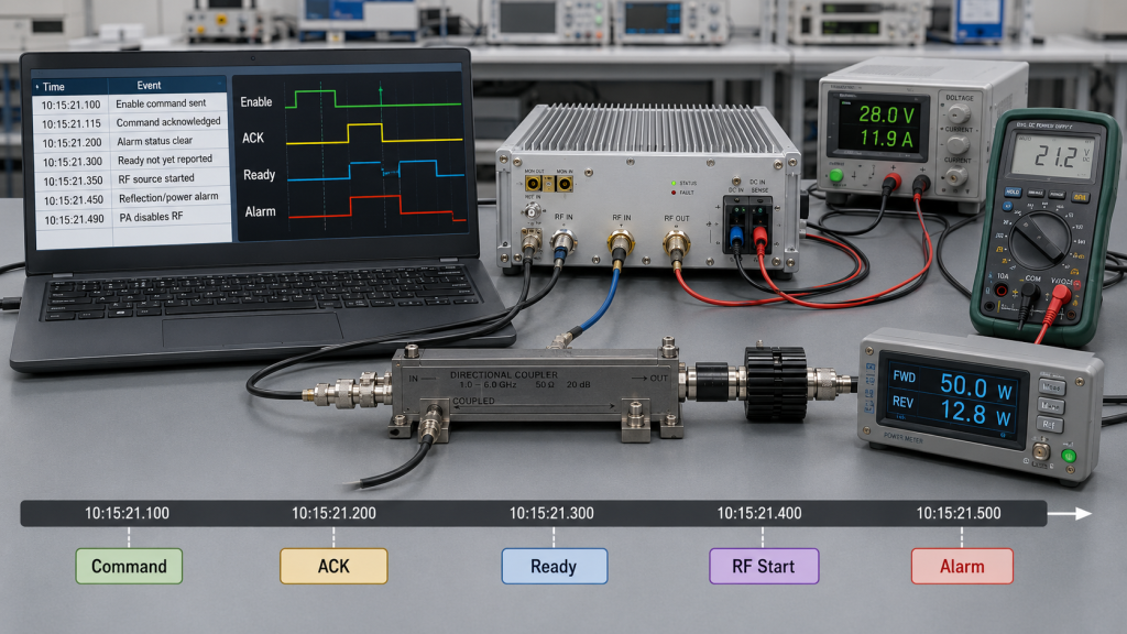
A single screenshot is rarely enough. The most useful evidence is a synchronized timeline showing what the controller sent, what the PA reported, and what the RF and DC measurements did at the same moment.
For example:
10:15:21.100  Enable command sent to Channel 3
10:15:21.115  Command acknowledged
10:15:21.220  Alarm status clear
10:15:21.310  Ready not yet reported
10:15:21.350  Controller starts RF source
10:15:21.410  Reflected-power alarm appears
10:15:21.430  PA disables RF
This sequence does not first point to a failed PA. It suggests that the RF source or load condition may have been applied before the required Ready state was confirmed.
Capture the original behavior before attempting a corrective action. Otherwise, the evidence needed to identify the real fault may disappear.
3. How to Diagnose Enable, Alarm, Status, and Reset Problems
Enable, Alarm, Status, and Reset should be diagnosed as one operating chain rather than four isolated signals.
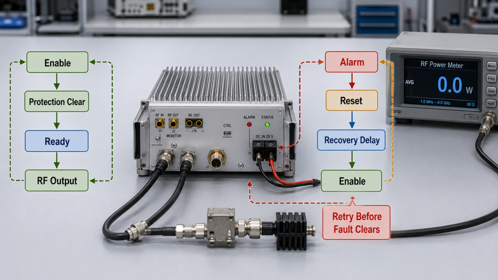
Enable is active but no RF output appears
Check in this order:
- Confirm the correct module address or physical channel.
- Confirm whether Enable is active-high or active-low.
- Measure the actual level at the PA connector.
- Check whether the PA acknowledged the command, where supported.
- Check whether the available protection status is clear.
- Check whether Ready was reported, where supported.
- Confirm stable PA-terminal voltage under the enable load.
- Confirm that RF input is present at the correct time.
- Confirm that the RF output load is connected and acceptable.
- Measure RF output with external equipment.
Enable may begin an activation sequence without proving that bias is ready, protection is clear, RF input is present, or stable output has been reached.
Some systems expose several separate states. Others provide only Enable and Alarm. The diagnostic process must follow the actual interface definition rather than assuming every PA offers the same telemetry.
Alarm remains active
First identify whether the alarm is:
- Real-time or latched
- General or category-specific
- Local or system-level
- Auto-clear or reset-required
- Associated with one module or a shared bus
Then check:
- Has the original fault condition disappeared?
- Is the RF load or VSWR now acceptable?
- Has temperature returned below the recovery boundary?
- Is PA-terminal voltage inside the permitted range?
- Is the alarm designed to clear automatically?
- Is Reset allowed while Enable remains active?
- Is the controller displaying cached status?
- Is the reset command reaching the correct module?
A reset command should not be used to hide an active fault. If the original condition remains, the alarm should return.
Status does not match RF behavior
Status feedback may represent:
- Command state
- Internal bias state
- Protection state
- Estimated forward power
- Calibrated detector output
- Ready state
- Last stored value
- Periodically updated telemetry
It may not be equivalent to a calibrated RF power measurement.
Check:
- Status source
- Update interval
- Timestamp
- Scaling
- Channel identity
- Address mapping
- Calibration
- Data type
- Whether the value is live or cached
Use external RF measurement equipment when confirming whether output is actually present.
Reset creates a restart loop
A restart loop often follows this pattern:
Fault
→ Reset
→ Immediate Enable
→ Same condition returns
→ Fault
→ Reset
Check:
- Whether Reset removed the root cause
- Whether Enable returns too quickly
- Whether the controller waits for the required completion state
- Whether retry delay is sufficient
- Whether the same address receives duplicate commands
- Whether repeated faults should force a latched-off state
- Whether DC voltage recovers before restart
- Whether the RF source and load are ready
A safe recovery sequence should prevent automatic retries from repeatedly stressing the PA.
RF PA Control Interface Symptom Matrix
| Symptom | First Evidence to Check | Likely Diagnostic Branch | Do Not Assume |
|---|---|---|---|
| Enable active but no RF | Ready, protection state, Vdc, RF input, output timing | Startup sequence, DC, or RF path | PA output stage failed |
| Alarm will not clear | Fault source, latch behavior, reset order | Protection and recovery | Reset command is defective |
| Status is stale | Address, timestamp, polling interval, timeout | Communication timing | Module stopped updating |
| Wrong channel responds | Module ID, bus address, channel map | Address or mapping fault | Wrong PA was installed |
| False alarm appears only during RF | Signal ground, cable route, shielding, RF leakage | Grounding or EMI | Alarm circuit is defective |
| Repeated restart loop | Fault log, retry interval, re-enable rule | Reset and recovery logic | Automatic restart is safe |
4. How to Separate Communication Timing from PA Hardware Failure
Communication problems should be isolated before the PA is replaced.
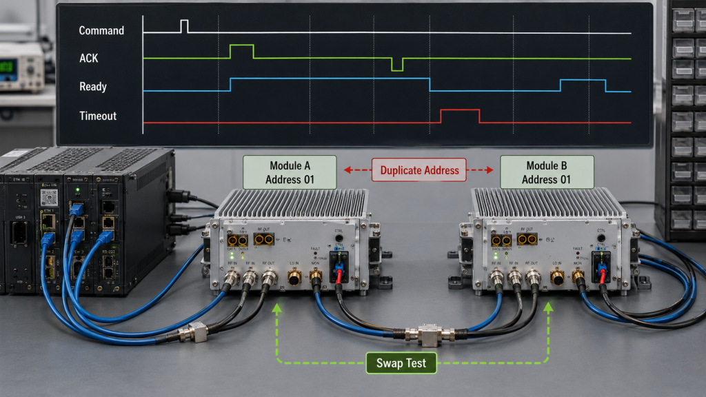
Common causes include:
- Wrong baud rate
- Wrong parity or frame format
- Wrong module address
- Duplicate address
- Incorrect channel map
- Command sent to the wrong bus
- Timeout shorter than the PA response time
- Polling too frequently
- Retry loop without delay
- Command accepted but operation not complete
- Stale status returned from the controller cache
- Protocol or firmware version mismatch
Check identity before behavior
For a multi-module system, verify:
- Physical module label
- Serial number
- Bus address
- Logical channel number
- Frequency-band assignment
- Controller channel map
- Returned identity or version data, where supported
A command that appears unsuccessful may simply have been sent to a different module.
Where supported, read back module identity before enabling RF.
Separate acknowledgement from completion
An acknowledgement may mean only:
The command was received.
It may not mean:
The PA completed the requested state change.
Depending on the available interface, the controller may need to wait for:
- Protection clear
- Bias ready
- Channel ready
- Temperature acceptable
- RF ready
- Stable output
When the fault appears during startup, compare the actual response time with the controller timeout.
Detailed AT command timing faults should be reviewed separately when ACK, Ready, Timeout, Retry, or multi-channel startup order is involved.
Test one command at a time
During diagnosis:
- Disable automatic retries.
- Test one module.
- Send one command.
- Record the complete available response.
- Wait for the defined completion state.
- Measure DC and RF behavior.
- Repeat with the same timing.
- Add other modules only after the single-module path is stable.
This method helps separate protocol errors from shared-bus or simultaneous-start problems.
Check whether the problem follows the module or the channel
A controlled swap test changes one variable at a time.
Perform swap tests only when the replacement channel, RF load, DC supply, cooling, input-drive limits, frequency range, and control-interface definition are compatible with the module under test.
Possible tests include:
- Keep the controller channel and replace only the PA.
- Keep the PA and move it to another compatible known-good channel.
- Keep both and change only the control cable.
- Keep the hardware and change only the module address.
- Keep the control path and use a verified RF load.
If the fault stays with the channel, investigate the controller, wiring, address map, or DC path.
If the fault follows the module under the same verified conditions, the PA becomes a stronger hardware suspect.
5. How to Check DC, Grounding, Wiring, and EMI Causes
A control-interface fault may originate outside the communication protocol.
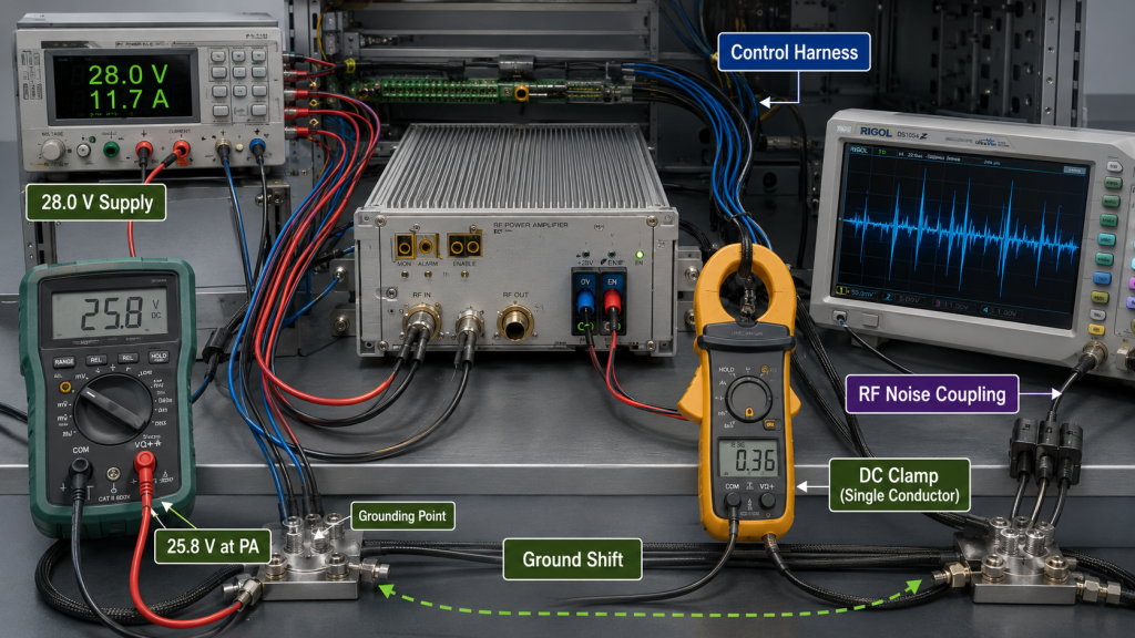
Check PA-terminal voltage during the fault
Control behavior can become unstable if voltage falls during:
- Enable
- RF startup
- High-current output
- Several simultaneous channels
- Fan activation
- Relay switching
Record voltage at the PA power terminals rather than relying only on the supply display.
If the fault occurs together with output loss, unstable startup, or repeated protection, separate RF PA output drops from DC power issues from the interface diagnosis.
Check active levels at the PA connector
For discrete signals such as Enable, Alarm, Ready, or Reset, verify:
- High and low voltage levels
- Default state during controller boot
- Pull-up or pull-down location
- Signal reference
- Input current
- Open-drain or push-pull behavior
- Whether the signal floats during cable disconnection
- Whether the state changes during RF transmission
Measure at the PA connector. A correct controller output does not prove that the same level reaches the module after a long harness or shared ground path.
Check grounding and signal reference
Suspect a grounding or reference problem when the fault appears only after:
- RF output starts
- PA current rises
- A cabinet door closes
- One cable is moved
- Multiple channels operate
- A long control cable is connected
- Another high-current load switches
Check:
- Shared DC return
- Signal-ground reference
- Ground voltage difference
- Shield termination
- Cable routing
- Common-mode coupling
- Connector retention
- Cabinet bonding
Detailed RF PA grounding and signal-reference faults should be reviewed when control levels shift or false alarms appear under RF load.
Check EMI and harness routing
RF leakage or switching noise can affect:
- Alarm lines
- Reset lines
- UART or RS485 communication
- Analog detector feedback
- Temperature feedback
- Module identification
- Controller inputs
Use practical checks:
- Separate control cables from RF output cables
- Avoid long parallel cable runs
- Check shield continuity
- Inspect connector backshells
- Confirm cabinet entry bonding
- Compare RF-off and RF-on behavior
- Test at different output levels
- Test one channel and then multiple channels
If the fault threshold follows RF output power rather than command timing, an EMI or grounding cause becomes more likely.
6. What Evidence to Collect Before Replacing the PA
The minimum snapshot in H2-2 preserves the original fault. The following checklist is the complete evidence package used to compare systems, assign corrective action, or decide whether module replacement is justified.
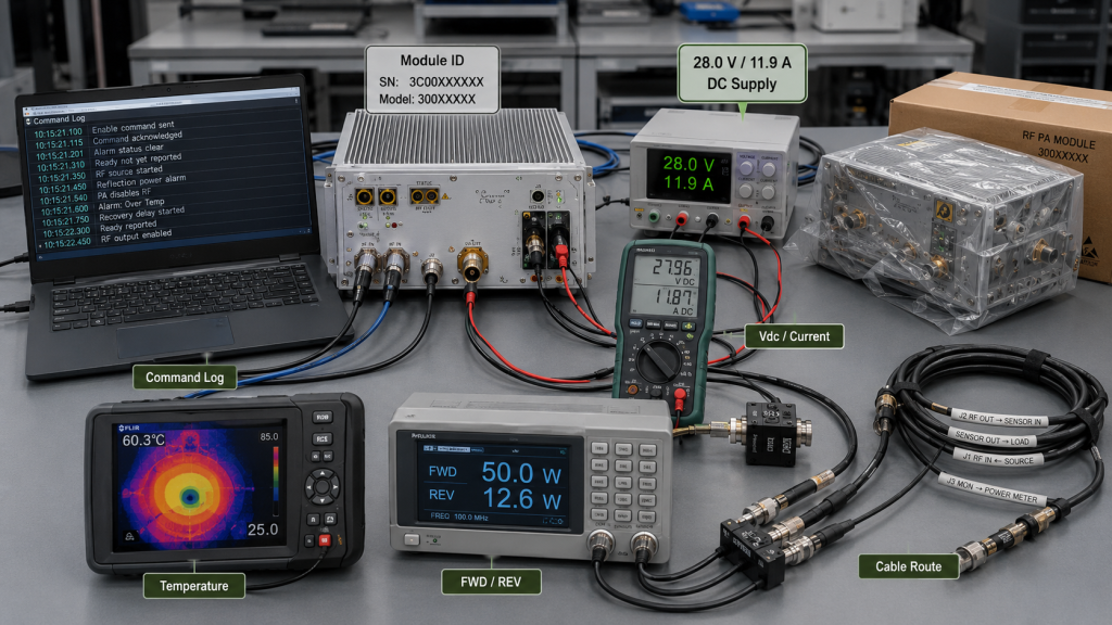
Do not replace the module only because:
- Enable produced no immediate RF
- An alarm appeared
- Status looked wrong
- Communication timed out once
- Reset did not clear the fault
- Another PA worked in a different setup
Control-Interface Fault Evidence Checklist
Module and Interface Identity
- Module model
- Module serial number
- Controller model
- Controller firmware version
- PA interface or firmware version
- Pinout revision
- Interface type
- Module address
- Channel map
Command and Timing Evidence
- Command sequence
- Command timestamps
- Enable level
- Available ACK response
- Available Ready response
- Timeout value
- Retry value
- Reset sequence
- Recovery delay
Alarm and Status Evidence
- Alarm category
- Latched or auto-clear behavior
- Status value
- Status timestamp
- Status update interval
- Reset result
- Protection state
- Repeated-fault behavior
Electrical and RF Evidence
- PA-terminal voltage
- PA current
- RF input state
- RF output
- Forward power
- Reflected power
- RF load or VSWR
- Module temperature
- Cooling condition
Wiring and Environment
- Control cable length
- Cable route
- Shield arrangement
- Signal-ground arrangement
- Connector condition
- RF-off result
- RF-on result
- Single-channel result
- Multi-channel result
Corrective Action and Pass Criteria
- Corrective action tested
- One variable changed at a time
- Result before and after the change
- Final root-cause conclusion
- Required recovery behavior
- Final pass criteria
The evidence should answer:
- Did the controller send the correct command?
- Did the PA receive it through the defined interface?
- Did the PA complete the requested state transition?
- Was the available protection status clear?
- Were DC, RF input, load, cooling, and temperature conditions valid?
- Did external measurement agree with the reported state?
- Did the fault follow the module, channel, cable, or operating condition?
Only after these checks isolate the fault to the module should the PA be treated as the likely hardware cause.
FAQ
Why does Enable go active but no RF output appear?
Enable may start the activation sequence without proving that protection is clear, the PA is Ready, RF input is present, the load is acceptable, or stable output has been reached. Check the states exposed by the actual interface and compare them with external DC and RF measurements.
Why does an RF PA alarm return after Reset?
Reset clears the stored fault state, not necessarily the fault cause. If voltage, temperature, reflected power, timing, or wiring remains outside the permitted boundary, the alarm should return.
Why do false control faults appear only during RF output?
RF output increases current and electromagnetic activity. The resulting voltage drop, ground-reference shift, RF coupling, shield current, or cable interference can disturb control and feedback signals even when communication works normally with RF off.
Conclusion
An RF PA control-interface fault should be diagnosed from the complete command, status, DC, RF, load, and timing sequence. Preserve the original failure first, then change one variable at a time to determine whether the fault follows the module, controller channel, address, cable, DC path, RF load, timing rule, grounding condition, or EMI environment.
RF SKYPOWER can review an RF PA control-interface fault before module replacement or cabinet rewiring. Submit the module model and serial number, interface type, pinout revision, active levels, module address, command and status logs, Enable and Reset sequence, alarm state, PA-terminal voltage and current, RF output condition, cable length, grounding arrangement, load or VSWR state, temperature, and the exact fault timeline.
Contact RF Engineering Team to separate controller, timing, power, wiring, EMI, RF-path, and PA hardware causes before the wrong component is replaced.