










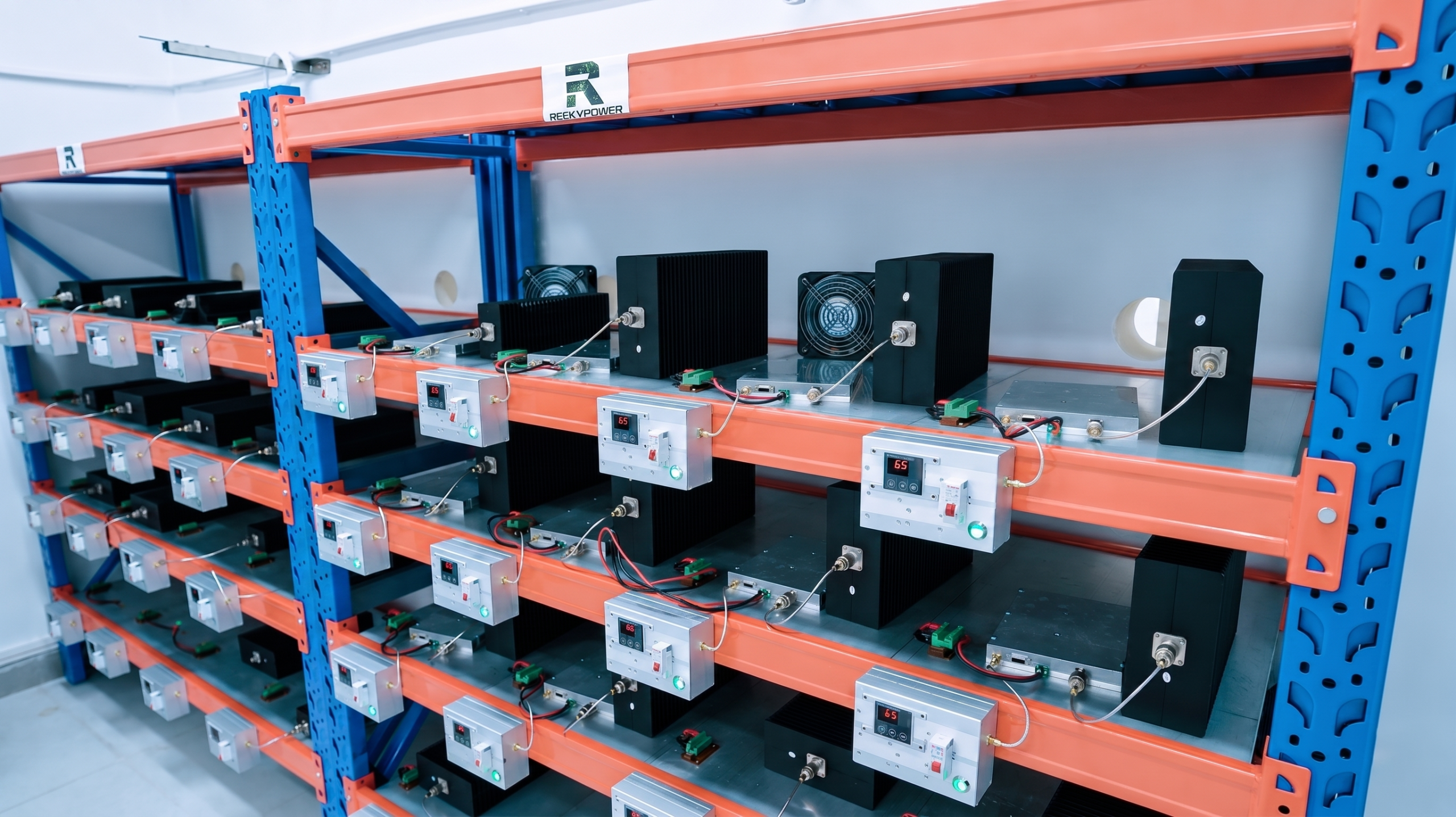
RF PA post-burn-in efficiency can appear to change even when the module itself has not materially drifted.
If the pre-burn-in and post-burn-in measurements use different thermal states, RF reference planes, loads, supply conditions, or output criteria, the changed percentage may describe a changed test setup rather than a changed PA.
The opposite problem is also possible: final Pout may still look acceptable while higher drive or DC current reveals that the operating point has shifted.
Before shipment acceptance, what must remain comparable—and which before-and-after measurements actually prove whether RF PA efficiency changed after burn-in?
1. What Must Stay Controlled Before Comparing Pre- and Post-Burn-In Efficiency?
A burn-in pass and an efficiency comparison answer different questions.
Burn-in records whether the module completed the required stress condition without prohibited behavior.
A post-burn-in efficiency comparison asks whether the defined efficiency metric changed under comparable operating and measurement conditions after the burn-in stress.
Pre- vs Post-Burn-In Efficiency Comparison Controls
| Comparison Item | What Must Remain Comparable | Risk if It Changes |
|---|---|---|
| Unit identity | Same module and S/N | Different DUTs are compared |
| Frequency | Same required test point | Different operating point changes efficiency |
| RF input condition | Same Pin rule, waveform, duty cycle, and defined PA-input reference plane | Gain or input-path changes may be hidden or exaggerated |
| RF output plane | Same corrected PA-port reference plane | RF path loss may look like PA drift |
| DC supply and boundary | Same defined Vdc condition and module-input measurement boundary | The DC denominator becomes non-comparable |
| Load | Same defined load or VSWR condition | Pout and current may shift |
| Thermal state | Same defined stabilization rule | Hot-state behavior may be mistaken for permanent drift |
| Measurement chain | Same or demonstrated-equivalent method | Instrument or path error may look like PA change |
This is why RF output after burn-in should be verified with the same reference-plane and operating-condition discipline used for the efficiency retest.
Pre-burn-in, hot-end, and final post-burn-in are not the same state
Three measurements may exist in one burn-in workflow:
- Pre-burn-in baseline — the defined reference condition before stress.
- Burn-in hot-end observation — PA behavior while the module is still in the accumulated thermal or electrical stress condition.
- Final post-burn-in retest — the shipment-acceptance measurement after the module reaches the defined final test condition.
These results serve different purposes.
A hot-end efficiency value can reveal behavior under sustained stress.
A final post-burn-in value shows whether the module still meets the agreed acceptance condition after burn-in.
Do not treat the hot-end value and final retest value as interchangeable.
2. How Should RF PA Efficiency Be Recalculated After Burn-In?
The efficiency metric must remain the same before and after burn-in.
For an illustrative module DC-to-RF efficiency metric:
Module DC-to-RF Efficiency (%) = Pout,PA-port / Pdc,module × 100%
For a module with one regulated DC input representing the complete defined electrical boundary:
Pdc,module = Vdc × Idc
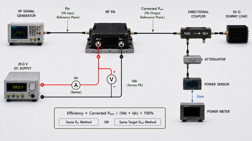
If several DC rails are included inside that module boundary, the applicable DC input powers should be summed rather than represented by one V × I term.
The RF numerator should remain fixed to the same corrected PA output reference plane.
A PA-port value should not be compared with a cabinet-output, feeder-end, or antenna-end value as though they were the same Pout.
If PAE, drain efficiency, or another metric is used instead, retain that metric’s own RF terms and DC measurement boundary for both tests.
Illustrative example—not RF SKYPOWER product test data
Suppose the required corrected PA-port output is 100 W.
Before burn-in:
Vdc = 28.0 V
Idc = 8.0 A
Pdc = 28.0 × 8.0 = 224 W
Module DC-to-RF Efficiency ≈ 100 / 224 × 100% ≈ 44.6%
After burn-in, suppose the same corrected 100 W PA-port output requires:
Vdc = 28.0 V
Idc = 8.5 A
Pdc = 28.0 × 8.5 = 238 W
Module DC-to-RF Efficiency ≈ 100 / 238 × 100% ≈ 42.0%
The numerical change deserves review.
It does not by itself prove permanent degradation.
The comparison is meaningful only if frequency, Pin method and input reference plane, RF output reference plane, Vdc condition, DC boundary, waveform, duty cycle, load, thermal state, and measurement method are comparable.
Same Pin or same Pout?
A project should state which comparison method is being used.
Same-Pin comparison
Keep Pin comparable at the defined PA input reference plane and use the same waveform and duty-cycle condition, then record:
- corrected Pout;
- Vdc;
- Idc;
- efficiency;
- temperature;
- protection state.
This method can expose changes in gain, output, and electrical burden at the same drive condition.
Same-target-Pout comparison
Adjust Pin at the defined PA input reference plane according to the agreed procedure until the same corrected PA-port output is reached, then record:
- required Pin;
- Vdc;
- Idc;
- efficiency;
- temperature;
- protection state.
This method can reveal whether more drive or DC power is required to reproduce the same RF output.
Neither method should be silently substituted for the other.
The report should state which acceptance method was used.
3. Which Post-Burn-In Changes Need Engineering Review?
A changed efficiency percentage is only one observation.
The stronger question is whether other RF, DC, thermal, or protection measurements changed with it.
Useful post-burn-in review signals include:
- increased Idc at a comparable operating point;
- increased Pin required for the same target Pout;
- reduced corrected Pout at the same Pin;
- temperature behavior that differs under the same cooling condition;
- unexpected protection or alarm activity;
- or a pre/post change that fails the predefined acceptance decision rule.

For complete burn-in procedure and monitoring requirements, keep the stress process in the dedicated RF PA batch burn-in workflow rather than recreating it inside the efficiency comparison.
A changed result is evidence—not automatically a root cause
Suppose post-burn-in Idc is higher.
Possible explanations may include:
- a real module operating-point change;
- different Pout;
- different Pin;
- a different thermal state;
- changed supply voltage;
- measurement uncertainty;
- or another changed test condition.
The same caution applies to temperature and protection logs.
A hotter post-burn-in result does not automatically prove efficiency degradation if cooling or ambient conditions changed.
A protection event does not automatically prove permanent aging.
Before assigning a cause, correlate the result with the complete test condition.
Measurement uncertainty belongs in the acceptance rule
A very small pre/post difference should not automatically be treated as module drift.
Define the acceptance limit and decision rule before testing, including how measurement uncertainty will be applied. Then use that same rule for every pre/post comparison.
This prevents an unexpected result from being judged by a different rule after the measurement is complete.
4. What Evidence Must Be Tied to Each Module S/N?
Post-burn-in efficiency evidence is strongest when the pre-test and post-test records belong to the same identified module.
At minimum, the record should connect the S/N to:
- hardware version where applicable;
- test-report version;
- frequency;
- actual Pin at the defined PA input reference plane;
- corrected PA-port Pout;
- Vdc;
- Idc;
- efficiency metric;
- RF and DC measurement boundaries;
- waveform and duty cycle;
- load or VSWR condition;
- temperature or agreed thermal state;
- burn-in duration and condition;
- protection or alarm record;
- and final acceptance result.
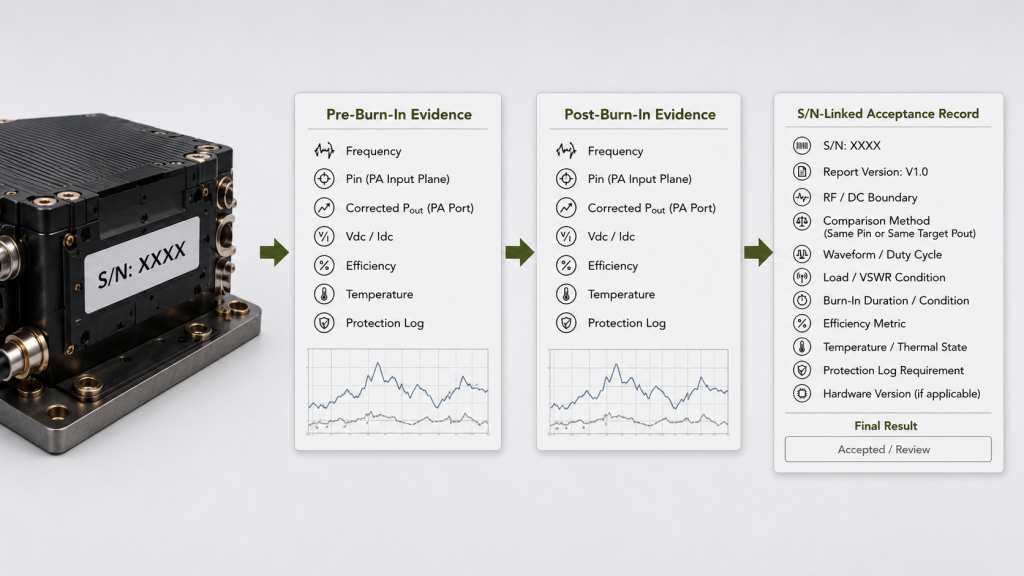
Where test-report revision control matters, keep the baseline and final evidence traceable through the RF power amplifier test report rather than comparing screenshots or unlabeled spreadsheets.
The purpose of S/N traceability is not administrative completeness.
It answers a practical question:
Did this specific module retain an acceptable operating point after the defined burn-in condition?
That also makes supplier comparison more meaningful.
Two suppliers should not be compared by a single “post-burn-in efficiency” percentage unless the metric, RF input and output reference planes, Pin/Pout comparison rule, Vdc condition, DC boundary, waveform, duty cycle, thermal state, load, and burn-in condition are comparable.
5. What Should the RFQ Define for Post-Burn-In Efficiency Acceptance?
“Burn-in passed” is not a complete post-burn-in efficiency requirement.
The RFQ should define what will be measured before burn-in, what will be measured afterward, and how the result will be judged.
Post-Burn-In Efficiency Acceptance Evidence
| Evidence | Pre-Burn-In | Post-Burn-In | Acceptance Rule |
|---|---|---|---|
| Corrected Pout | Recorded at defined PA-port plane | Repeated at same plane | Within agreed RF limit |
| Pin | Recorded at defined PA input plane under stated comparison method | Repeated or adjusted by same rule | Change reviewed where applicable |
| Vdc / Idc | Recorded at defined module boundary and Vdc condition | Repeated under same condition | No unacceptable electrical drift |
| Efficiency | Same metric and equation | Recalculated using same method | Meets the predefined acceptance decision rule |
| Thermal condition | Defined stabilization state | Same acceptance state | Comparable condition achieved |
| Protection status | Recorded | Recorded | No unexplained prohibited event |
| S/N evidence | Baseline linked to unit | Final data linked to same unit | Complete traceability |
For a practical RFQ, specify:
- required frequency points;
- efficiency metric and equation;
- corrected PA-port Pout;
- same-Pin or same-target-Pout comparison method;
- available or controlled Pin at the defined PA input reference plane;
- Vdc condition and Idc measurement boundary;
- waveform and duty cycle;
- burn-in duration;
- cooling condition;
- load or VSWR boundary;
- pre-burn-in stabilization state;
- burn-in hot-end monitoring requirement;
- final post-burn-in stabilization rule;
- allowed Pout, current, and efficiency drift;
- measurement-uncertainty decision rule;
- protection-log requirement;
- and S/N-linked test-report format.
The broader shipment-release criteria should remain consistent with the C-UAS RF PA acceptance checklist rather than letting a single efficiency result become the complete acceptance decision.
When comparing RF Power Amplifier Modules, require pre- and post-burn-in efficiency data under the same defined RF, DC, waveform, load, and thermal boundaries rather than accepting a generic “burn-in passed” statement.
FAQ
Can an RF PA pass burn-in but still fail the efficiency retest?
Yes.
Burn-in completion and post-burn-in efficiency acceptance are different checks.
A module may complete the defined stress period without a prohibited event but still show a pre/post change in Pout, Pin, Idc, efficiency, temperature, or another acceptance parameter that fails the predefined acceptance rule.
Should pre- and post-burn-in efficiency be compared at the same Pin or the same Pout?
Either method can be useful if it is defined before testing and used consistently.
A same-Pin comparison shows how output and electrical burden change at the same drive condition.
A same-target-Pout comparison shows whether additional drive or DC power is required to reproduce the same corrected RF output.
In either case, Pin must refer to the defined PA input reference plane.
Does a post-burn-in efficiency change prove permanent aging damage?
No—not by itself.
A changed efficiency result is an observation.
Before attributing it to permanent module degradation, confirm that the RF input and output reference planes, DC boundary, Vdc condition, waveform, duty cycle, thermal state, load, comparison method, and measurement uncertainty are controlled or properly accounted for.
Conclusion
A completed burn-in record does not by itself prove that RF PA efficiency remained unchanged.
Post-burn-in efficiency can support shipment acceptance only when the pre- and post-burn-in measurements use the same defined efficiency metric, PA input and output reference planes, DC boundary and supply condition, waveform, duty cycle, load condition, thermal rule, and comparison method.
The burn-in hot-end result and the final post-burn-in retest should also remain separate: one describes behavior under accumulated stress, while the other determines whether the module meets the agreed final acceptance condition.
A changed efficiency percentage deserves engineering review when comparable evidence also shows changes in Idc, required Pin, corrected Pout, thermal behavior, or protection activity. The final decision should use the acceptance limit and measurement-uncertainty rule defined before testing rather than assigning a root cause from the percentage alone.
For post-burn-in efficiency acceptance, send RF SKYPOWER the required frequency points, efficiency metric, PA-port Pout, PA-input Pin reference plane and comparison rule, Vdc and Idc boundary, waveform and duty cycle, burn-in duration, cooling condition, load or VSWR boundary, thermal stabilization rule, allowed drift, measurement-uncertainty decision rule, protection-log requirement, and S/N-linked report format.
Those definitions make the before-and-after result suitable for an engineering acceptance decision instead of turning “burn-in passed” into an unsupported efficiency claim.