











A C-UAS RF PA acceptance process can include a valid factory RF test and still leave the buyer with an unresolved shipment decision. The measured power may be acceptable, while the delivered serial number, hardware state, stress record, protection evidence, or integration boundary is governed by a different acceptance requirement.
The risk is not simply missing paperwork. For a custom RF Power Amplifier Module entering a C-UAS project, the buyer needs to know which evidence is mandatory for release, which evidence applies to each individual unit, and which evidence applies only to a batch, configuration, or project-level requirement.
Before the shipment is released, what must the acceptance checklist prove—and which missing evidence should actually block release under the agreed acceptance plan?
1. Why a Passed RF Test Is Not Yet a Shipment Release Decision
An RF test report answers a specific question:
What was measured on a defined unit or test sample under defined conditions?
A shipment release decision is broader.
If the agreed RFQ or acceptance plan also requires identity, traceability, configuration, stress, protection, integration, or documentation evidence, a valid RF power result does not by itself establish shipment release.If those reliability requirements are still being defined before supplier approval, first use the RF power amplifier reliability before RFQ framework to align the operating boundary, evidence conditions, and evidence scope before applying this shipment-release checklist.

The acceptance checklist should connect three things:
- What the project required
- What evidence was produced
- Which release decision that evidence supports
Different projects may use different evidence structures. One may require final RF measurements for every delivered serial number, while another may combine per-unit RF measurements with batch-level stress evidence and configuration-level protection validation.
Neither structure should be presented as evidence for a scope it does not cover.
Use a Practical Evidence-Scope Framework
For this checklist, it is useful to separate evidence into four practical scopes:
| Evidence scope | What it applies to | Typical purpose |
|---|---|---|
| Per-unit | One delivered S/N | Links measurements or release records to one physical unit |
| Batch-level | A defined production lot or batch | Supports evidence that applies to multiple units under an agreed batch plan |
| Configuration-level | Hardware, BOM, firmware, protection logic, or approved revision | Confirms the technical state followed by the delivered hardware |
| Project-level | RFQ, limits, test points, reference planes, environmental or interface requirements | Defines how acceptance is performed and judged |
This is a practical organizational framework, not a universal industry classification. The exact terminology and required evidence should follow the agreed RFQ or acceptance plan.
Sampling and qualification are not separate evidence scopes:
- sampling defines which units were tested;
- qualification defines what design, process, or configuration was validated;
- evidence scope defines what population or boundary the result legitimately supports.
Evidence from one scope should not be presented as proof for another.
2. How to Link the Delivered S/N to the Correct Acceptance Evidence
The first acceptance question should be:
Which physical RF PA does this evidence belong to?
Depending on the agreed plan, useful identity evidence may include:
- model or part number;
- serial number;
- hardware revision;
- firmware or control version where applicable;
- approved configuration or BOM revision;
- production lot or batch identification where relevant;
- final inspection or release record.
The purpose is to prevent measurements, inspection records, or configuration evidence from becoming detached from the delivered hardware.
For detailed report checks, see the RF PA test report verification.
When One Report One Unit Applies
When unit-level production acceptance is required, the required evidence should remain traceable to the delivered serial number.
A practical chain is:
One Unit → One Serial Number → Required Test Dataset → Release Record → Traceable Acceptance Evidence
This does not mean every possible test must be repeated on every unit.
It means that any result described as unit-level evidence should actually be linked to that delivered S/N. Batch-level, configuration-level, and project-level evidence should remain identified according to their actual scope.
If sampling or qualification is used, the covered units, configuration, or project boundary should be stated separately.
For deeper traceability checks, see the traceable RF PA test evidence chain.
3. What RF Test Boundaries Must Match Before Release
A measured RF value is useful only when the buyer knows what condition and measurement boundary produced it.
Relevant items may include:
- frequency or required frequency points;
- actual input drive where relevant;
- output power;
- gain;
- Vdc and Idc;
- load condition;
- duty cycle or CW condition;
- thermal state;
- cooling condition;
- test duration where relevant;
- measurement reference plane;
- cable, connector, attenuator, coupler, or other path corrections where applicable.
The exact list depends on the parameter being accepted.For gain-specific acceptance, use the RF power amplifier gain flatness check to align the frequency points, Pin/Pout reference planes, load, thermal state, and flatness reporting method before applying the acceptance limit.
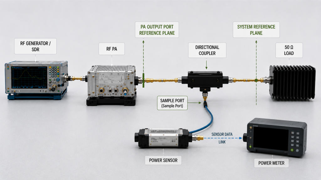
A meaningful RF output comparison requires the relevant frequency, operating condition, correction method, and measurement reference plane to be defined consistently.
For C-UAS projects that require point-by-point wideband review, C-UAS wideband RF PA performance verification shows how to connect project-defined frequencies, Actual Pin, Pout reference planes, operating conditions, and evidence scope before treating the wideband performance requirement as satisfied.
Do Not Mix Measurement Reference Planes
A power value measured at the PA output port is not automatically the same as a value measured after a cable, coupler, filter, feeder, or antenna path.
If the requirement is specified at the PA port, downstream path loss should not be silently included in the PA result.
If the requirement is specified at another system reference plane, the relevant RF-path loss or correction method must be defined before the result is compared with the requirement.
For installed-path decisions, see the RF PA feeder cable loss check.
A Test Result Should Prove Only What Was Tested
A result from one frequency, load, thermal state, or operating condition should not automatically be expanded into a claim covering conditions that were not tested.
The acceptance checklist should distinguish:
- measured result;
- corrected result;
- nominal specification;
- project target;
- guaranteed requirement where contractually defined;
- engineering inference.
These terms are not interchangeable.
4. Which Stress, Thermal, and Protection Evidence Belongs in the Acceptance Pack
When the project includes stress, thermal, or protection requirements, the checklist should identify the required evidence scope and the validation method used within that scope.
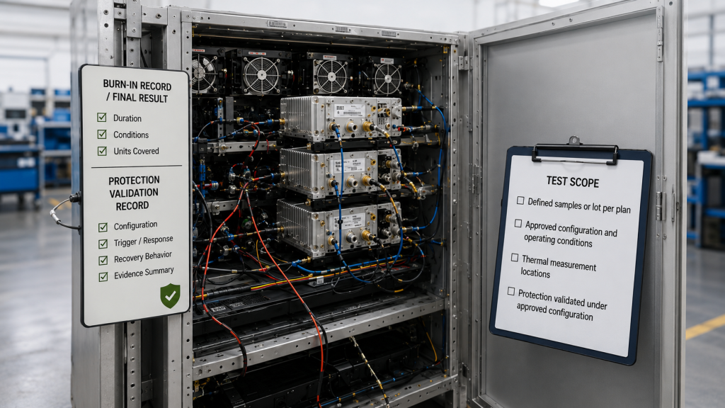
Burn-In and Stress Evidence
Depending on the approved plan, burn-in evidence may need to identify:
- covered units or samples;
- RF and DC operating condition;
- duty cycle;
- thermal or cooling condition;
- duration;
- monitoring method;
- alarms or interruptions;
- final result.
A batch or sampled burn-in record can support batch-level evidence when that is the agreed structure. It should not be described as per-unit burn-in evidence unless the delivered S/N was actually included.
For detailed burn-in evidence, see RF PA batch burn-in validation.
Thermal Evidence
A thermal result should identify:
- where temperature was measured;
- relevant RF operating condition;
- cooling boundary;
- ambient or inlet-air condition where required;
- stabilization or test-duration rule;
- protection behavior where applicable.
A cold-state pass should not automatically be treated as stabilized hot-state evidence. An external surface temperature should not automatically be treated as transistor junction temperature or an internal protection-sensor reading.
Protection Evidence
Protection evidence should remain tied to the approved configuration and validation scope.
Depending on the project, the acceptance pack may identify:
- required protection function;
- threshold or configuration file;
- hardware or firmware state;
- test condition;
- trigger behavior;
- response;
- recovery or reset behavior;
- validation scope.
A configuration-level validation may be sufficient for some projects, while others may require additional unit-level verification.
For controlled threshold files or protection settings, see RF PA alarm threshold files before acceptance.
5. Which Integration Boundaries Must Match the Delivered Configuration
A C-UAS RF PA may pass its factory RF test while the delivered configuration still creates an integration mismatch.
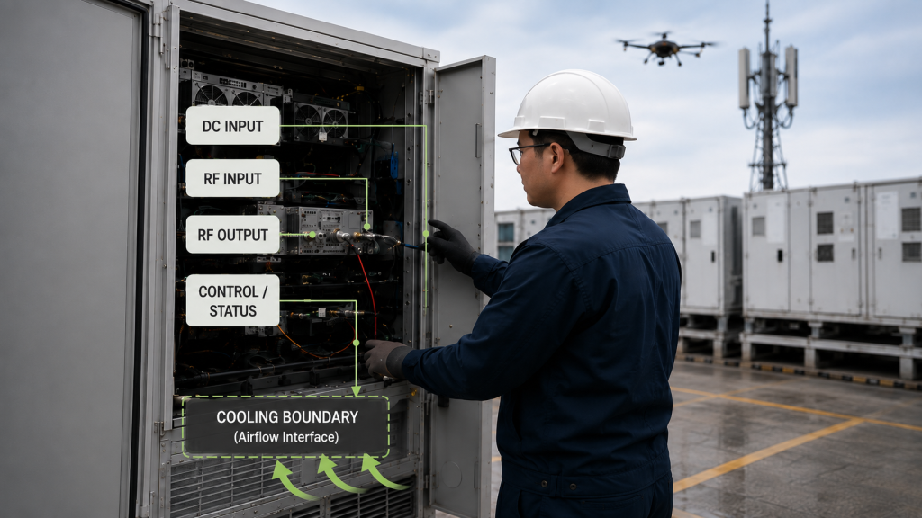
Shipment acceptance should therefore verify the interfaces the buyer actually depends on, such as:
- DC input voltage and connector;
- current requirement;
- RF input and output interfaces;
- mechanical mounting;
- cooling method;
- airflow or cold-plate boundary where applicable;
- control, alarm, or status interface;
- communication protocol where required;
- delivered cable or harness configuration;
- mechanical envelope.
The checklist should focus on whether the delivered configuration matches the approved project interface.
Configuration Changes Must Remain Traceable
If a relevant hardware, BOM, firmware, interface, or manufacturing change occurred after approval, the shipment record should identify the applicable revision and the evidence required by the project.
A change is not automatically a failure.
The acceptance question is whether the delivered configuration remains covered by the approved technical and evidence boundary.
6. Build the Acceptance Pack Around the Release Decision
The checklist should not ask only:
“Do we have a report?”
It should ask:
“Does the available evidence satisfy the agreed release requirements for this shipment?”
| Acceptance area | Evidence scope | Evidence to verify | Release rule |
|---|---|---|---|
| Unit identity | Per-unit | S/N, model, applicable configuration | Must match delivered hardware |
| RF performance | Per-unit or batch-level, as specified | Defined measurements under agreed RF test boundaries | Must meet applicable RFQ / acceptance limits |
| Configuration | Configuration-level | Hardware, BOM, firmware, interface, or approved revision | Must match approved state or accepted change |
| Burn-in / stress | Per-unit or batch-level, as specified | Covered units, conditions, duration, and result | Must follow agreed stress and sampling plan |
| Thermal | As specified | Defined thermal point, condition, and acceptance rule | Must follow agreed thermal boundary |
| Protection | Per-unit or configuration-level, as specified | Required function, threshold, response, and validation record | Must follow approved protection plan |
| Integration interfaces | Configuration-level or project-level | Power, RF, control, cooling, and mechanical interfaces | Must match approved integration boundary |
| Shipment documents | Per-unit, batch-level, or project-level, as required | Test reports, packing data, and release records | Must satisfy agreed document package |
This is a practical framework, not a universal industry standard.
The important point is that each required item has a defined evidence scope and a defined release consequence before the shipment is judged.
7. How to Define Release Status Before Testing
If a project uses Pass, Review, and Hold, those statuses should be defined in the RFQ, acceptance plan, or other agreed documentation before testing begins.
Other projects may use different terminology.
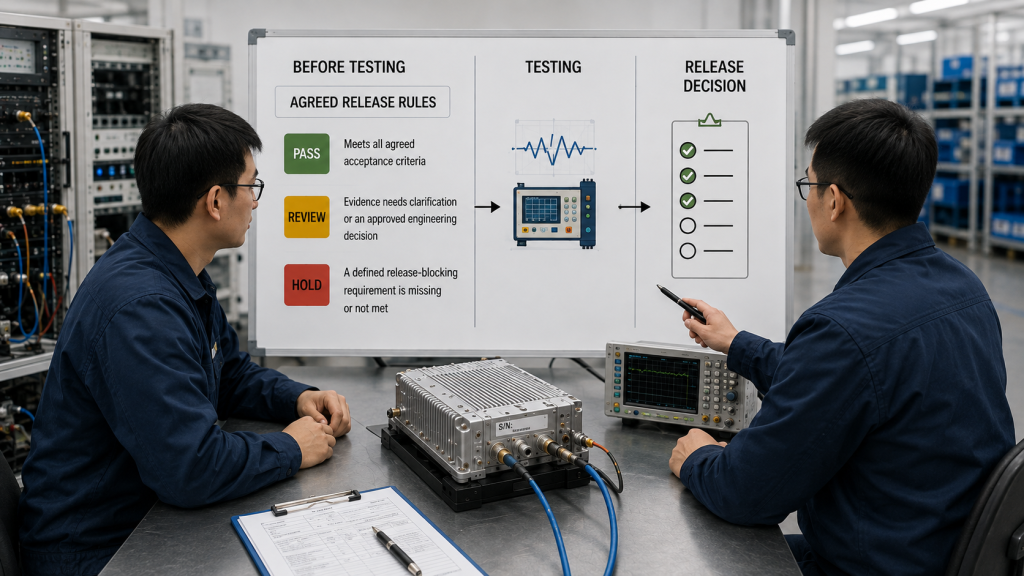
The agreed release logic should identify:
- which evidence is mandatory;
- which limits create a failure;
- which missing items may enter engineering review;
- whether re-test is allowed;
- whether corrective evidence can close an open item;
- which conditions block shipment release.
The following is only an example:
| Status | Example meaning | Typical next action |
|---|---|---|
| Pass | Required evidence is complete and agreed limits are met | Release according to project process |
| Review | Evidence needs clarification or an approved engineering decision | Review before release |
| Hold | A defined release-blocking requirement is missing or not met | Do not release until resolved |
The actual status names and rules must follow the agreed project documentation.
A missing unit-linked RF report, for example, may be a Hold item in a project requiring per-unit final acceptance. In another approved structure, the relevant evidence may be batch-level and not require an individual report for every delivered S/N.
8. Final Buyer Check Before Shipment Release
Before release, the buyer should be able to confirm:
- which S/Ns and configurations are being delivered;
- which evidence is per-unit, batch-level, configuration-level, or project-level;
- whether required frequencies and RF reference planes are defined;
- whether raw and corrected measurements are distinguished;
- whether relevant RF, DC, load, duty-cycle, cooling, and thermal conditions are documented;
- what burn-in, thermal, and protection scope was agreed;
- whether required integration interfaces match the delivered configuration;
- which items are mandatory for release, review, or hold.
If these answers are clear, the checklist can support a defensible shipment decision.
If evidence scopes are mixed or release rules remain undefined, adding more test screenshots may not solve the underlying acceptance problem.
FAQ
Is an RF PA test report enough for shipment acceptance?
Not necessarily. A valid RF test report proves the measurements it contains under the documented conditions. If the agreed acceptance plan also requires identity, configuration, stress, protection, integration, traceability, or shipment documentation, those items must be evaluated separately.
Does every delivered RF PA need its own test report?
Only when the agreed structure requires unit-level evidence for that result. Batch-level, configuration-level, and project-level evidence should remain identified according to their actual scope.
Who should define Pass, Review, and Hold criteria?
If those status names are used, their criteria should be defined in the RFQ, acceptance plan, or other agreed project documentation before final results are judged.
Conclusion
A C-UAS RF PA acceptance checklist should prove more than whether an amplifier produced RF power on a factory bench.
Before shipment release, the checklist should connect project requirements to the correct evidence scope: per-unit, batch-level, configuration-level, or project-level. Sampling and qualification may determine how evidence is generated, but they should not be confused with the scope that evidence actually supports.
RF measurements must retain the conditions needed to interpret them correctly, including frequency, operating condition, correction method, thermal state, load condition, and measurement reference plane. Unit-level claims should remain linked to the delivered serial number, while broader evidence should remain identified according to its actual scope.
Release terminology and blockers should also be defined before final acceptance. If a project uses Pass, Review, and Hold, those statuses should follow the agreed project rules rather than being treated as universal industry standards.
Before requesting shipment approval, define the required frequency points, target output and measurement reference plane, quantity, duty cycle, Vdc, load or VSWR boundary, cooling condition, control interface, protection requirements, evidence scope, S/N traceability rule, and required acceptance-report format.
For a custom RF Power Amplifier Module, include these requirements in the RFQ so the requested module configuration and shipment evidence are evaluated against the same acceptance plan. Contact us with your frequency range, target output, quantity, duty cycle, DC supply, cooling method, control interface, VSWR boundary, and required test-report format for your C-UAS RF PA project.