










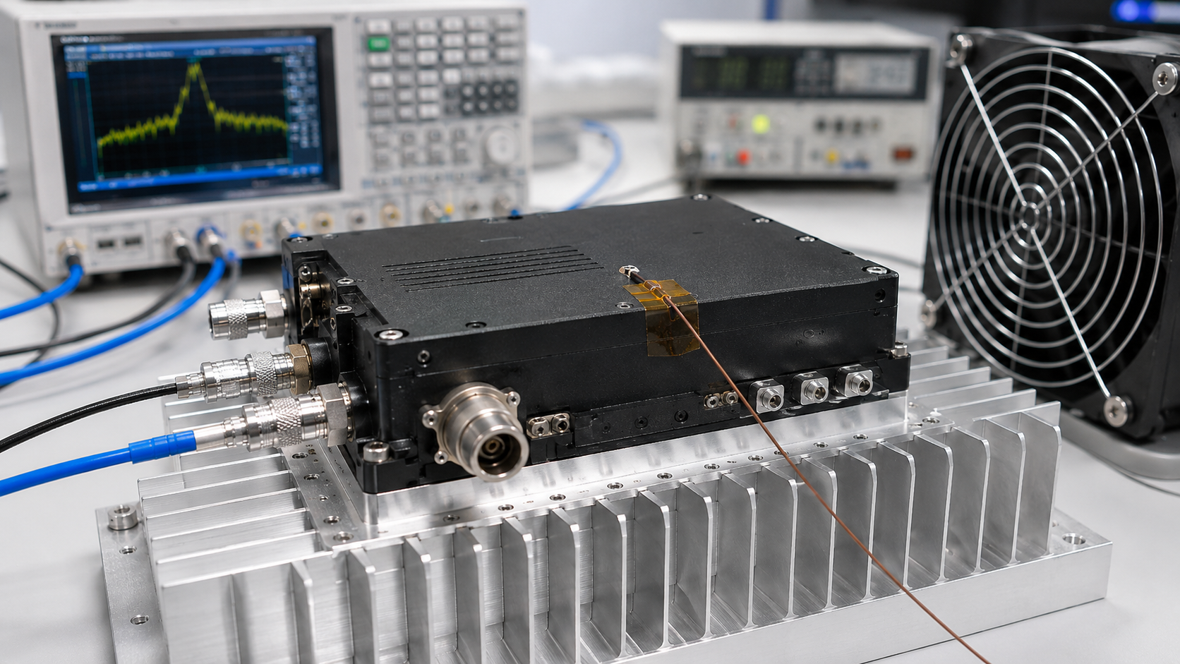
An RF PA temperature probe reading can look precise enough for thermal approval even when the measurement point behind that number has not been clearly defined.
That becomes a serious acceptance problem when a factory test measures the module case, an integration test measures the heatsink, and a vehicle team records cabinet air temperature. The numbers may all be real, yet they may not be directly comparable.
Before a buyer accepts or rejects the thermal result, which measurement point and operating boundary must be defined so both sides are evaluating the same condition?
1. Why RF PA Thermal Readings Become Misleading Without a Defined Measurement Point
A temperature probe, thermocouple, or surface sensor measures temperature at a specific physical location. That location may be the module housing, copper base, heat spreader, heatsink, air inlet, air outlet, cabinet wall, or another defined surface.
The number itself does not identify which thermal condition it represents.
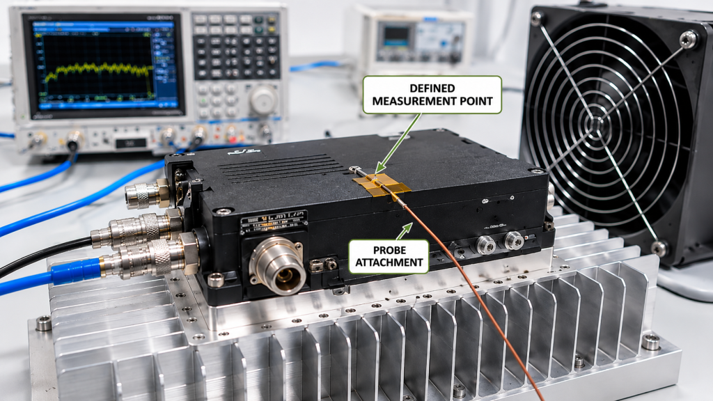
For example, a report may show an apparently acceptable temperature while the probe is attached to a relatively cool edge of the housing. Another test may show a higher value because the probe is closer to the main heat-flow path. Both readings can be physically valid at their own measurement points.
The problem starts when they are treated as if they describe the same thermal condition.
A temperature value therefore should not be interpreted without knowing:
- the exact measurement point;
- how the probe is attached;
- the RF operating condition;
- duty cycle;
- load condition;
- ambient or inlet-air condition;
- airflow and cooling boundary;
- test duration;
- output power and DC operating condition;
- protection behavior.
A defined measurement point is the first requirement for meaningful thermal evidence, but the point alone does not establish whether an RF PA has passed thermal acceptance.
The temperature must be interpreted together with the operating condition that created it.
2. What Each RF PA Temperature Probe Location Can—and Cannot—Represent
Different probe locations answer different engineering questions.
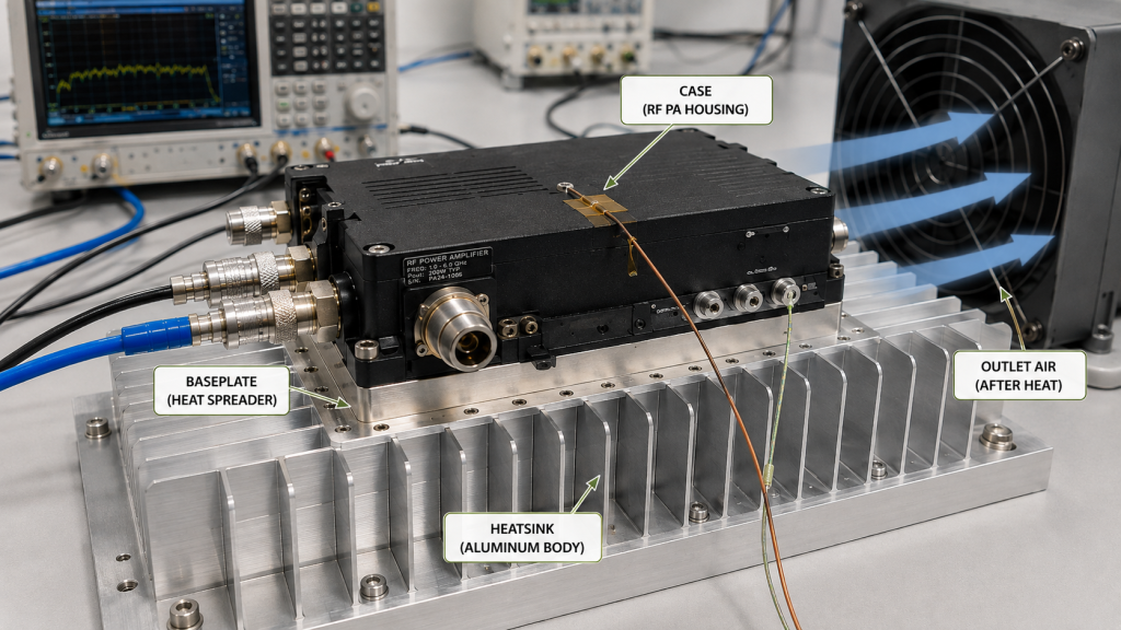
Module Case or Housing
A probe on the RF PA housing measures the surface temperature at that location.
It can help show how the module case responds as the amplifier heats, but one housing point should not automatically be treated as the hottest location on the module.
A housing-edge value and a value measured closer to the main heat-flow region may differ even during the same test.
Copper Base or Heat Spreader
A probe on the copper base or heat spreader can help evaluate the local thermal condition where heat is transferred away from the active RF section toward the cooling structure.
This can be useful when reviewing heat spreading, mounting contact, or the thermal interface.
However, an external surface temperature is still an external surface temperature.
A surface probe near the PA heat-source region can indicate local surface heating, but it does not by itself establish transistor junction temperature or the temperature seen by an internal protection sensor. Those quantities should only be compared when the relevant thermal path or correlation has been defined.
Heatsink Center and Heatsink Edge
A heatsink measurement can help show how the cooling structure responds to the PA thermal load.
The center and edge of the same heatsink may not operate at the same temperature. Their readings can be influenced by heat spreading, mounting position, fin geometry, airflow distribution, and the thermal interface between the module and heatsink.
When a test is intended to evaluate heat spreading, baseplate contact, mounting-interface behavior, or heatsink performance, define those measurement points as part of the RF PA heatsink design check before comparing factory and installed results.
Air Inlet and Air Outlet
Air temperature answers a different question from case or heatsink temperature.
An inlet-air measurement can describe the cooling air entering the thermal system. An outlet-air probe can show how the air temperature changes along the airflow path.
But outlet-air temperature alone does not quantify how much heat the cooling system removes. Quantifying heat removal requires additional information, including the relevant airflow rate and inlet-to-outlet temperature change.
The outlet-air reading also should not be treated as the PA device temperature or module case temperature.
Cabinet Air
Cabinet-air temperature describes the thermal environment around the module.
It can be important in an enclosed system, especially when several heat-generating components share the same space.
But a cabinet-air value cannot by itself prove that the RF PA case, baseplate, heatsink, or internal device temperature is acceptable.
There Is No Universal Probe Point
There is no single temperature-probe location that is correct for every RF PA test.
The appropriate point depends on what the test is intended to evaluate.
The buyer and supplier should therefore define whether the measurement is intended to represent:
- module-case temperature;
- a baseplate or heat-spreader condition;
- heatsink behavior;
- cooling-air condition;
- cabinet environment;
- or another project-specific thermal boundary.
The important question is not whether one probe point is universally right or wrong.
It is whether the selected point actually represents the condition being used for the acceptance decision.
3. How Probe Location Can Change an RF PA Acceptance Decision
A probe placed at a different point from the defined acceptance location may produce a valid local temperature reading while representing a different thermal condition from the one the test is intended to evaluate.
The resulting acceptance decision can therefore change even when the RF PA operating condition itself has not changed.
A defined probe location is necessary for interpreting an RF PA thermal result, but it is not sufficient for acceptance; the reading must also be tied to the operating condition and thermal boundary under which it was measured.
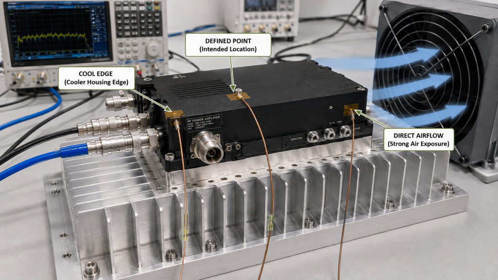
A common error is placing the probe on a cooler area of the housing. The temperature may appear acceptable while the thermal condition at another relevant location remains unknown.
Another error is placing a surface probe directly in a strong cooling-air path. The local measurement may stabilize quickly even though other parts of the cooling structure follow a different thermal trend.
A third error is comparing two different measurement locations as though they were the same result.
For example:
- the factory measures the module case;
- the integrator measures the heatsink;
- the installed system records cabinet air.
Those temperatures should not be compared directly as one thermal metric without a defined relationship between the measurement points.
Pass, review, and fail should therefore be assigned against a predefined measurement point, operating boundary, and project-specific acceptance limit.
A temperature limit defined for one location should not automatically be transferred to another location.
| What the buyer sees | What may be missing | Better evidence | Why it matters |
|---|---|---|---|
| Temperature looks acceptable | Probe may be on a cooler housing location | Mark the exact measurement point | The reported value may not represent the intended thermal condition |
| Stable temperature curve | Probe may be directly influenced by local airflow | Record probe position and airflow boundary | Local stability may not represent the complete cooling path |
| Factory and installed temperatures differ | Different measurement points or attachment methods may have been used | Define comparable measurement locations and attachment methods | Prevents false factory/field comparisons |
| No over-temperature alarm | External probe and internal protection sensor may monitor different locations | Review external temperature evidence together with the protection log | Absence of an alarm does not define the external thermal boundary |
| Report contains only one temperature value | RF, DC, mounting, duty cycle, and cooling conditions may be missing | Record the operating and thermal conditions with the temperature | Acceptance needs context, not an isolated number |
Temperature should also be reviewed with the RF and DC behavior of the amplifier.
For hot-state testing, useful evidence may include:
- frequency;
- input drive where relevant;
- output power;
- Vdc and Idc;
- load condition;
- duty cycle;
- ambient or inlet-air condition;
- cooling condition;
- temperature trend;
- test duration;
- alarm, rollback, or shutdown status.
If an over-temperature alarm appears while RF output still looks normal, review the RF PA thermal alarm together with probe location, temperature trend, airflow, and protection status before changing the acceptance limit.
This is also why RF PA power after thermal soak should be evaluated under a defined thermal boundary rather than from an isolated final power or temperature screenshot.
If a thermal result changes while the PA heats, the observation should first be treated as a test result. It should not automatically be assigned to a specific internal failure mechanism without additional evidence.
4. How to Keep Factory and Vehicle Thermal Results Comparable
Factory and installed-system tests do not need to reproduce every physical detail of each other.
But when their temperature results are compared directly, the relevant measurement boundaries must be equivalent or explicitly reconciled.
Factory and installed temperatures should be compared only when the measurement point, attachment method, operating condition, and relevant thermal boundary are equivalent or explicitly reconciled.
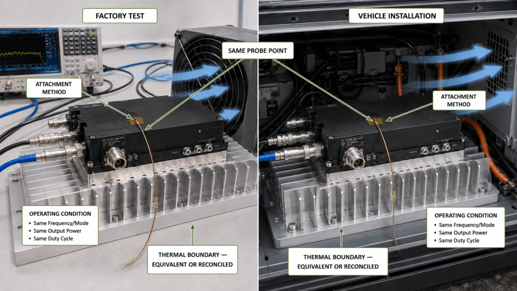
Four items deserve particular attention.
1. Use the Same Defined Measurement Point When Direct Comparison Is Required
A housing-edge temperature from a factory test should not be compared directly with cabinet-air temperature from a vehicle test and called the same result.
If a different measurement location must be used after integration, the report should identify that difference rather than hide it behind one generic “PA temperature” label.
2. Define the Probe Attachment Method
A probe held against a surface by tape, a clamp, an adhesive, or another sensor mounting method may not produce identical measurement behavior.
The report should therefore identify how the sensor is attached when repeatability matters.
When absolute temperatures are compared for acceptance, the sensor type and measurement method should also remain consistent or be documented.
Poor or changing physical contact can make a temperature trend difficult to interpret.
3. Keep the Operating Condition Comparable
The same measurement point can still produce different results when the operating condition changes.
Relevant conditions may include:
- output power;
- frequency;
- duty cycle;
- DC supply condition;
- load or VSWR boundary;
- test duration;
- ambient temperature;
- airflow;
- fan state;
- cabinet configuration.
Vehicle installations make these boundaries especially important because enclosure geometry, restricted airflow, nearby heat sources, and changing environmental conditions can differ substantially from an open bench.
The goal is not to force a vehicle installation to look like a factory bench.
The goal is to identify which conditions changed before deciding whether two temperature results contradict each other.
4. Separate the Measurement Point From the Complete Thermal Boundary
The probe point tells the buyer where the temperature was measured.
The thermal boundary explains the conditions around that measurement.
For an installed RF PA, the thermal boundary may include:
- mounting method;
- heatsink configuration;
- thermal interface;
- airflow path;
- fan condition;
- cabinet space;
- ambient or inlet-air temperature;
- duty cycle;
- nearby heat sources.
This distinction prevents one probe location from being treated as a complete description of the system.
5. What RF PA Temperature-Probe Evidence Should Be Defined in the RFQ
An RFQ that asks only for a “thermal test” or “temperature report” leaves too much open to interpretation.
The supplier may provide a legitimate temperature value, while the buyer assumes that the number represents a different measurement point or installed condition.
A weak requirement may simply say:
- thermal test required;
- temperature report required;
- module must operate in a vehicle installation.
None of these statements defines what the temperature actually represents.
Define the Thermal Evidence Before Testing
A stronger RFQ should define the evidence that will be used for approval before the test is performed.
At minimum, the buyer should decide which measurement point is relevant and which operating conditions must accompany that result.
| RFQ item | Customer input needed | What it establishes |
|---|---|---|
| Measurement point / thermal surface | Exact case, baseplate, heatsink, air, or other defined point | Which thermal condition the temperature reading represents |
| Probe attachment method | Defined sensor-contact or mounting method | How the measurement is physically obtained |
| Ambient or inlet-air condition | Defined test-environment temperature | The surrounding thermal condition |
| Airflow condition | Fan state, airflow path, or cabinet cooling boundary | How cooling is applied during the test |
| Duty cycle | CW or defined pulsed / on-off profile | The thermal loading condition |
| Frequency | Test frequency or required frequency points | Which RF operating condition produced the thermal result |
| Output power | Required RF output during the thermal test | Whether the thermal result corresponds to the intended RF load |
| Vdc / Idc | DC operating condition | Whether DC behavior is recorded with the thermal result |
| Load condition | Defined dummy load or RF path / VSWR boundary | The RF load used during testing |
| Test duration | Required operating period or stabilization rule | When the acceptance measurement is taken |
| Protection record | Alarm, rollback, shutdown, or recovery status where applicable | Whether protection behavior occurred during the test |
| Module S/N | Delivered-unit identity | Which physical unit the evidence belongs to |
The S/N requirement serves a different purpose from the probe-location requirement.
Probe location and operating conditions determine what the temperature reading represents; the module serial number determines which delivered unit the acceptance evidence belongs to.
If unit-level acceptance evidence is required, the RFQ can define a traceability chain such as:
One Unit → One Serial Number → One Thermal Dataset → One Test Report → Traceable Acceptance Evidence
That is an acceptance and documentation requirement. It should not be confused with the physical validity of the temperature measurement itself.
Define the Acceptance Boundary Before Seeing the Result
The RFQ should also define how the thermal result will be judged.
A project-specific limit should identify the measurement location to which the limit applies.
For example, a maximum value defined for a module-case point should not automatically be applied to:
- heatsink temperature;
- outlet-air temperature;
- cabinet-air temperature;
- or an internal sensor reading.
If the project uses more than one thermal point, the RFQ should identify which point is informational and which point is used for acceptance.
This makes later factory-to-system comparison much clearer.
FAQ
Is one temperature reading enough for RF PA thermal acceptance?
Not by itself. The report should identify where the temperature was measured, how the probe was attached, and the operating and thermal conditions under which the reading was obtained. Acceptance should then be based on the predefined limit for that measurement boundary.
Where should an RF PA temperature probe be placed?
There is no universal location for every project. The probe location should match the thermal condition being evaluated, such as module-case temperature, baseplate behavior, heatsink performance, cooling-air condition, or cabinet environment. An external surface probe should not automatically be treated as a transistor junction-temperature measurement or internal protection-sensor reading.
What should an RFQ define for repeatable RF PA thermal testing?
Define the measurement point, probe attachment method, ambient or inlet-air condition, cooling and airflow boundary, duty cycle, frequency, RF output, Vdc / Idc, load condition, test duration or stabilization rule, protection record, acceptance limit, and required unit traceability.
Conclusion
RF PA temperature probe location should be defined before thermal acceptance because each measurement point represents a different part of the thermal system.
The exact physical point, probe attachment method, operating condition, thermal boundary, and applicable acceptance limit should be identified before factory and installed results are compared. A module-case temperature should not automatically be treated as heatsink temperature, cabinet-air temperature, transistor junction temperature, or the reading of an internal protection sensor.
A defined probe location is therefore necessary, but meaningful thermal approval also requires the RF, DC, load, cooling, duty-cycle, ambient, duration, and protection conditions that created the result.
Before an RFQ or thermal-acceptance review, prepare the required frequency points, target RF output, duty cycle, Vdc / Idc condition, module mounting method, heatsink and airflow boundary, ambient-temperature range, temperature-probe locations, probe attachment method, test duration or stabilization requirement, protection limits, and required S/N-linked report format.
For a custom RF Power Amplifier Module, include these conditions in the RFQ so the required factory test boundary, installed-system comparison, and thermal acceptance evidence are defined before approval.
Contact RF SKYPOWER with the RF operating requirements and thermal-test boundary required for your project.