










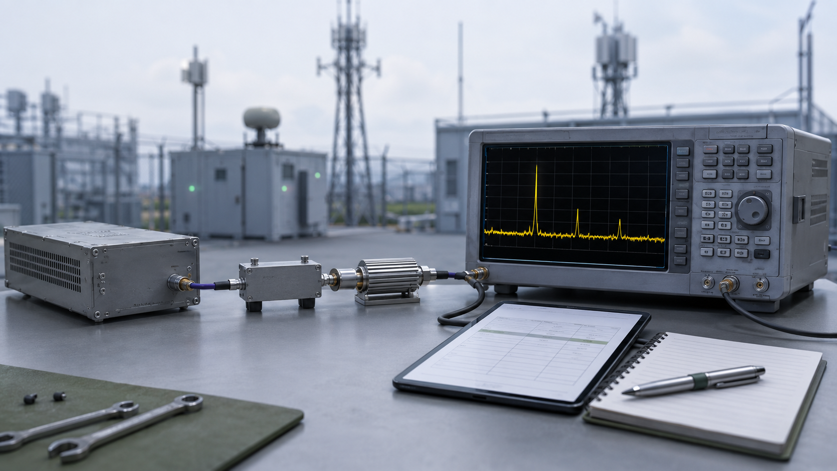
A clean harmonic screenshot can still be weak acceptance evidence when the analyzer settings and RF sample path are not traceable. RBW setting is part of that boundary, but one marker value does not show whether two harmonic results were measured under equivalent conditions.
This matters when a result sits near the harmonic limit or when a factory report and field retest disagree. A changed marker does not by itself prove whether the RF PA changed or the measurement condition changed.
So what must be fixed and recorded before an RF PA harmonic result can support a real pass/fail decision?
1. Why a Harmonic Screenshot Is Not Enough for Acceptance
A spectrum screenshot can show a fundamental signal and harmonic markers, but the image alone may not show how those values were produced.
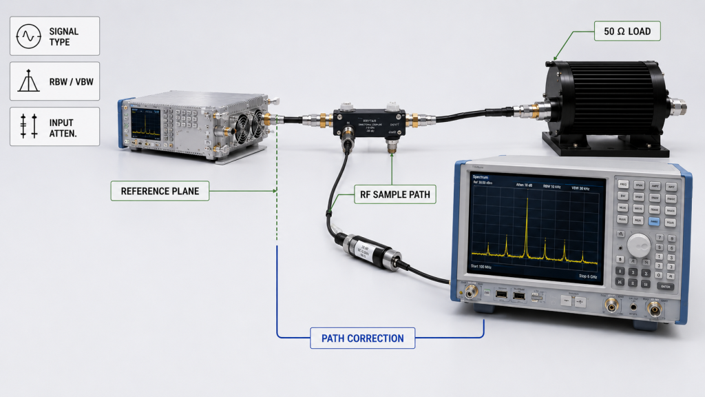
For RF PA acceptance, the measurement record may need to identify:
- signal type: CW, pulsed RF, or modulated;
- fundamental frequency;
- harmonic order and harmonic frequency;
- Pout or defined RF operating condition;
- harmonic limit;
- whether the limit is specified in dBm or dBc;
- RBW and VBW;
- detector, trace, or averaging mode;
- span and sweep or acquisition condition;
- analyzer input attenuation and reference level;
- RF sample-path configuration;
- frequency-specific path correction;
- declared measurement reference plane;
- analyzer identity and calibration evidence;
- unit S/N.
Without those conditions, two similar screenshots may not represent equivalent measurements.
A clean trace therefore does not, by itself, prove that the RF PA meets the required harmonic limit.
Absolute dBm and Relative dBc Are Different Acceptance Quantities
The report should state whether the harmonic requirement is an absolute level in dBm or a relative level in dBc.
For a stable discrete CW test, when the corrected fundamental and harmonic are both referenced to the same declared plane:
Harmonic dBc = Corrected Harmonic Level in dBm − Corrected Fundamental Level in dBm
This relationship is meaningful only when both values belong to the defined measurement condition and the applicable frequency-dependent corrections are known.
For pulsed or modulated signals, do not automatically apply this marker-based relationship if the acceptance procedure defines an integrated, channelized, or other bandwidth-dependent measurement. Use the power definition and measurement bandwidth specified for that test.
A dBc result is incomplete when the fundamental reference, reference plane, or correction basis is missing.
2. What RBW Changes—and What It Does Not
Resolution bandwidth defines the analyzer bandwidth used around a measured spectral component.
Changing RBW can affect:
- frequency resolution;
- displayed noise contribution;
- separation of nearby spectral components;
- sweep or acquisition time;
- the appearance of low-level signals near the analyzer or measurement-system floor.
But RBW does not change the harmonic generated inside the RF PA.
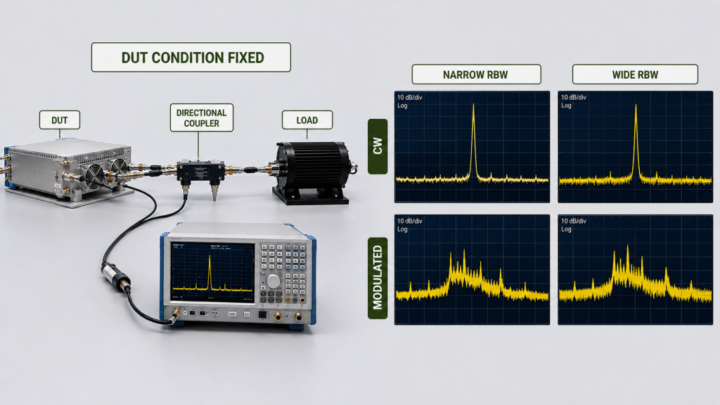
For a stable discrete CW harmonic, RBW should not be treated as a mechanism that changes the PA’s generated harmonic level.
If the measured amplitude moves materially after RBW changes, review the measurement method before assigning the difference to the PA. Relevant checks include:
- signal bandwidth;
- detector or trace mode;
- averaging;
- sweep or acquisition state;
- analyzer or measurement-system floor;
- analyzer linearity;
- sample-path correction.
CW, Pulsed, and Modulated Signals Need Different Interpretation
A stable single-tone CW harmonic can behave like a discrete spectral component.
Pulsed or modulated RF may distribute spectral energy over a wider bandwidth, so changing RBW can change how much energy appears in an individual marker or measurement bin.
A marker-based CW harmonic method and a bandwidth-defined or integrated measurement are therefore not automatically interchangeable.
The acceptance procedure should define the signal type and measurement method used.
RBW Does Not Work Alone
RBW is only one analyzer setting.
VBW, detector or trace mode, averaging, span, sweep time, input attenuation, and reference level can also affect how the result is displayed or measured.
A narrower RBW generally requires more sweep or acquisition time. If acquisition settings are manually shortened, confirm that the trace has reached the required measurement state before using the marker for acceptance.
The goal is not to force one universal analyzer setup. It is to make the measurement recipe reproducible.
3. What Can Make a Harmonic Pass/Fail Result Misleading
A harmonic marker can cross a limit because of a real DUT difference, a measurement-condition difference, or both.
Before assigning the result to the RF PA, check the complete measurement boundary.
The Fundamental Reference May Be Missing
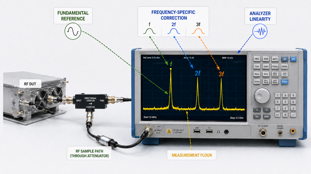
For a dBc requirement, the harmonic result depends on the fundamental reference.
A report that shows only:
Second harmonic: −60 dBc
is incomplete if the buyer cannot determine:
- which fundamental result was used;
- whether it was raw or corrected;
- where it was referenced;
- how the harmonic itself was corrected.
A relative result needs a traceable reference.
The Sample-Path Correction May Be Wrong at the Harmonic Frequency
A spectrum sample path can include:
- directional coupler;
- attenuator;
- RF cable;
- adapters;
- connectors;
- other fixture components.
Their behavior can change with frequency.
If the fundamental is at f, the second harmonic is at 2f and the third harmonic is at 3f.
A correction established at the carrier frequency should not automatically be reused at the second or third harmonic.
The spectrum sample path must remain characterized or otherwise valid at each measured harmonic frequency.
The reported fundamental and harmonic values should be traceable to the declared measurement reference plane using the correction applicable to each frequency.
The broader high-power RF PA test should keep corrected fundamental power, harmonic or spurious results, analyzer coverage, and sample-path correction tied to the same operating condition.
The Analyzer Can Contribute Its Own Distortion
A high-power RF PA should be sampled through a measurement path that keeps the analyzer input within its intended operating range.
Even then, the analyzer can contribute distortion if the internal signal level is too high.
If the apparent harmonic changes when analyzer input attenuation is changed while the DUT operating condition remains fixed, check for analyzer-generated distortion before assigning the harmonic to the PA.
More attenuation can also reduce measurement margin for a very low harmonic, so analyzer linearity and the analyzer or measurement-system floor should be considered together.
A Low Marker Can Be Limited by the Measurement Floor
If a harmonic is close to the analyzer or measurement-system floor, the marker may not support the precision implied by the displayed value.
The report should show enough measurement context to establish whether the harmonic had sufficient margin for the required acceptance decision.
Harmonic Measurement Failure Modes
| What the buyer sees | Possible measurement issue | Evidence to check | Acceptance risk |
|---|---|---|---|
| Harmonic marker changes after RBW changes | Measurement bandwidth, detector, sweep state, or signal bandwidth may differ | RBW, signal type, detector, trace mode, acquisition settings | Two results may not be directly comparable |
| Harmonic changes when analyzer attenuation changes | Analyzer-generated distortion may be contributing | Input attenuation, reference level, repeated measurement with DUT unchanged | Apparent harmonic may not come only from the PA |
| Very low harmonic sits near the analyzer or measurement-system floor | Measurement margin may be insufficient | RBW, attenuation, trace state, floor level | Reported value may overstate measurement confidence |
| dBc result cannot be reconstructed | Fundamental reference or reference plane is missing | Corrected fundamental, corrected harmonic, declared reference plane | Relative limit cannot be audited |
| 2f or 3f result uses the same correction as the carrier | Frequency-dependent sample-path response may be ignored | Coupler, attenuator, cable, calibration or characterized path data | Corrected harmonic level may be wrong |
| Factory and field markers differ | DUT conditions, measurement recipes, or RF paths may not be equivalent | Operating condition, signal type, load, analyzer settings, sample path, correction | Difference may be incorrectly assigned to the PA |
This table identifies what should be checked; it should not be used to assign a root cause from one screenshot.
4. How to Compare Factory and Field Harmonic Results
A field retest does not become directly comparable with a factory test simply because both measurements use a spectrum analyzer.
For direct comparison, check whether both tests used equivalent:
- RF PA operating condition;
- fundamental frequency;
- signal type;
- Pout or drive condition;
- harmonic order;
- dBm or dBc definition;
- fundamental reference;
- declared reference plane;
- RBW and VBW;
- detector or trace mode;
- averaging;
- span and acquisition condition;
- input attenuation and reference level;
- RF sample path;
- frequency-specific correction;
- load condition.
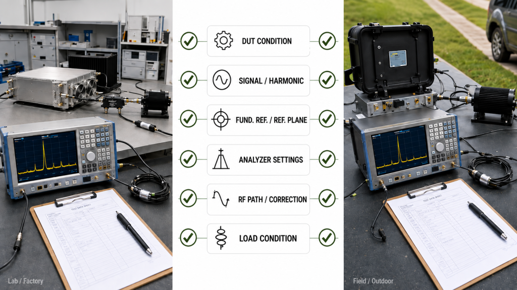
Factory and field harmonic results are directly comparable only when the DUT operating condition, signal type, fundamental reference, harmonic order, load boundary, measurement path, correction basis, declared reference plane, and relevant analyzer settings are equivalent.
If the results disagree, preserve both measurement records before changing analyzer settings or adjusting the RF PA.
At minimum, retain:
- raw analyzer result;
- harmonic frequency;
- analyzer settings;
- sample-path configuration;
- correction applied;
- declared reference plane;
- corrected harmonic result;
- fundamental reference where dBc is used;
- module S/N.
Changing the test recipe until two screenshots look similar removes the evidence needed to understand why they differed.
What Harmonic Test Evidence Should the Report and RFQ Define?
A useful harmonic acceptance record should make the measurement reproducible and the pass/fail calculation auditable.
Harmonic evidence should also sit within the broader C-UAS RF PA acceptance checklist, where the RF result, measurement boundary, and S/N-linked shipment evidence are reviewed together.
| Evidence item | What should be recorded | Why it matters |
|---|---|---|
| Unit identity | RF PA S/N where unit-level acceptance is required | Links the evidence to the tested unit |
| Signal type | CW, pulsed RF, or modulated | Defines how the spectral result should be interpreted |
| Fundamental frequency | Exact test frequency | Defines the carrier |
| RF operating condition | Required Pout, Pin, or defined drive condition | Keeps the PA operating point comparable |
| Harmonic order / frequency | Required harmonic and actual measurement frequency | Connects analyzer coverage and correction to the correct frequency |
| Limit format | dBm or dBc | Defines the acceptance quantity |
| Fundamental reference | Corrected fundamental value where dBc is used | Allows the relative result to be reconstructed |
| Declared reference plane | Plane represented by corrected fundamental and harmonic levels | Prevents analyzer-input, sample-port, and PA-output values from being treated as equivalent |
| RBW / VBW | Applied bandwidth settings | Defines measurement resolution and filtering |
| Detector / trace mode | Detector, trace, or averaging mode | Keeps interpretation consistent |
| Span / acquisition condition | Span, sweep time, or relevant acquisition state | Supports repeatability |
| Input attenuation / reference level | Analyzer input settings | Helps assess linearity and measurement floor |
| RF sample path | Coupler, attenuator, cable, adapters, and fixtures | Defines how the analyzer receives the RF sample |
| Frequency-specific path correction | Correction applicable at the measured frequency | Connects raw analyzer data to the declared plane |
| Analyzer identity / coverage | Analyzer ID and applicable frequency range | Confirms equipment identity and harmonic-frequency coverage |
| Calibration evidence | Applicable analyzer calibration record or status | Supports calibration traceability |
| Raw / corrected harmonic result | Original analyzer result and final corrected value | Preserves the calculation path |
| Final judgment | Pass, review, or other defined disposition | Connects evidence to the acceptance decision |
For a stable discrete CW test using dBc, the report should allow this evidence chain to be reconstructed:
DUT Operating Condition → Fundamental Frequency → Harmonic Frequency → Raw Analyzer Result → Frequency-Specific Path Correction → Declared Reference Plane → Corrected Harmonic Level → Corrected Fundamental Reference → dBc Result → Applicable Limit
For pulsed or modulated tests, use the spectral power definition and measurement bandwidth required by the applicable acceptance procedure.
Where acceptance is required per delivered unit, that evidence should remain linked to the unit S/N and its test record:
One Unit → One S/N → One Test Dataset → One Test Report → Traceable Acceptance Evidence
This does not require every project to use the same report format.
What the RFQ Should Define
If harmonic evidence is part of module approval, the RFQ should define, where relevant:
- fundamental frequencies;
- signal type;
- required Pout or drive condition;
- harmonic orders and limits;
- dBm or dBc definition;
- fundamental reference for dBc;
- declared reference plane;
- required RBW / VBW or acceptable measurement method;
- detector / trace / averaging requirement;
- harmonic frequency coverage;
- analyzer linearity requirement where applicable;
- RF sample-path configuration;
- frequency-specific correction method;
- load condition;
- required raw and corrected data;
- unit-level traceability;
- test-report format.
This prevents unlike measurement methods or correction bases from being treated as equivalent.
When harmonic evidence is part of module approval, define the signal condition, harmonic limits, analyzer settings, declared reference plane, spectrum-path correction, and S/N-linked report requirement before selecting the RF PA module.
FAQ
Is a Harmonic Screenshot Enough for RF PA Acceptance?
Not by itself.
A screenshot may omit the signal type, RBW, detector, input attenuation, fundamental reference, declared reference plane, RF sample path, or correction used to produce the final result.
The acceptance record should preserve enough information to reconstruct the measurement and judgment.
Can Changing RBW Change a CW Harmonic Reading?
RBW changes measurement resolution, noise bandwidth, and sweep behavior, but it does not change the harmonic generated by the RF PA.
For a stable discrete CW harmonic, a material change in measured amplitude after changing RBW should trigger a review of the measurement method before the change is assigned to the PA.
Why Can Factory and Field Harmonic Results Disagree?
The two tests may use different DUT conditions, signal types, fundamental references, reference planes, analyzer settings, RF sample paths, correction data, or loads.
A different harmonic marker therefore does not automatically prove that the PA itself changed.
What Should the RFQ Define for Harmonic Testing?
The RFQ should define the signal condition, fundamental frequencies, harmonic orders and limits, dBm or dBc basis, fundamental reference, declared reference plane, relevant analyzer settings, sample-path correction, load condition, and test-report traceability.
For pulsed or modulated signals, the applicable power definition and measurement bandwidth should also be defined.
Conclusion
An RBW setting does not change the harmonic generated by an RF PA. It is one part of the measurement method used to resolve and evaluate that harmonic.
A defensible harmonic pass/fail decision requires the DUT operating condition, signal type, harmonic definition, fundamental reference, analyzer settings, measurement floor, sample-path correction, load boundary, and declared reference plane to be clear enough to reproduce the result.
For a stable discrete CW harmonic, a large change in marker amplitude after changing RBW should first trigger a review of the measurement method. The same applies when changing analyzer input attenuation changes the apparent harmonic: analyzer-generated distortion should be checked before assigning the result to the DUT.
At 2f, 3f, or other harmonic frequencies, sample-path correction and analyzer coverage must apply at the actual harmonic frequency rather than being assumed from the carrier setup.
For pulsed or modulated signals, use the spectral power definition and measurement bandwidth required by the acceptance procedure rather than automatically applying a discrete-CW marker method.
For an RFQ that requires traceable RF PA harmonic evidence, provide the fundamental frequencies, signal type, required Pout condition, harmonic orders and limits, dBm or dBc definition, fundamental reference, declared reference plane, analyzer settings, RF sample path, correction method, load condition, and required unit-level test report.
Contact RF SKYPOWER with these acceptance requirements before the harmonic test procedure is finalized.