










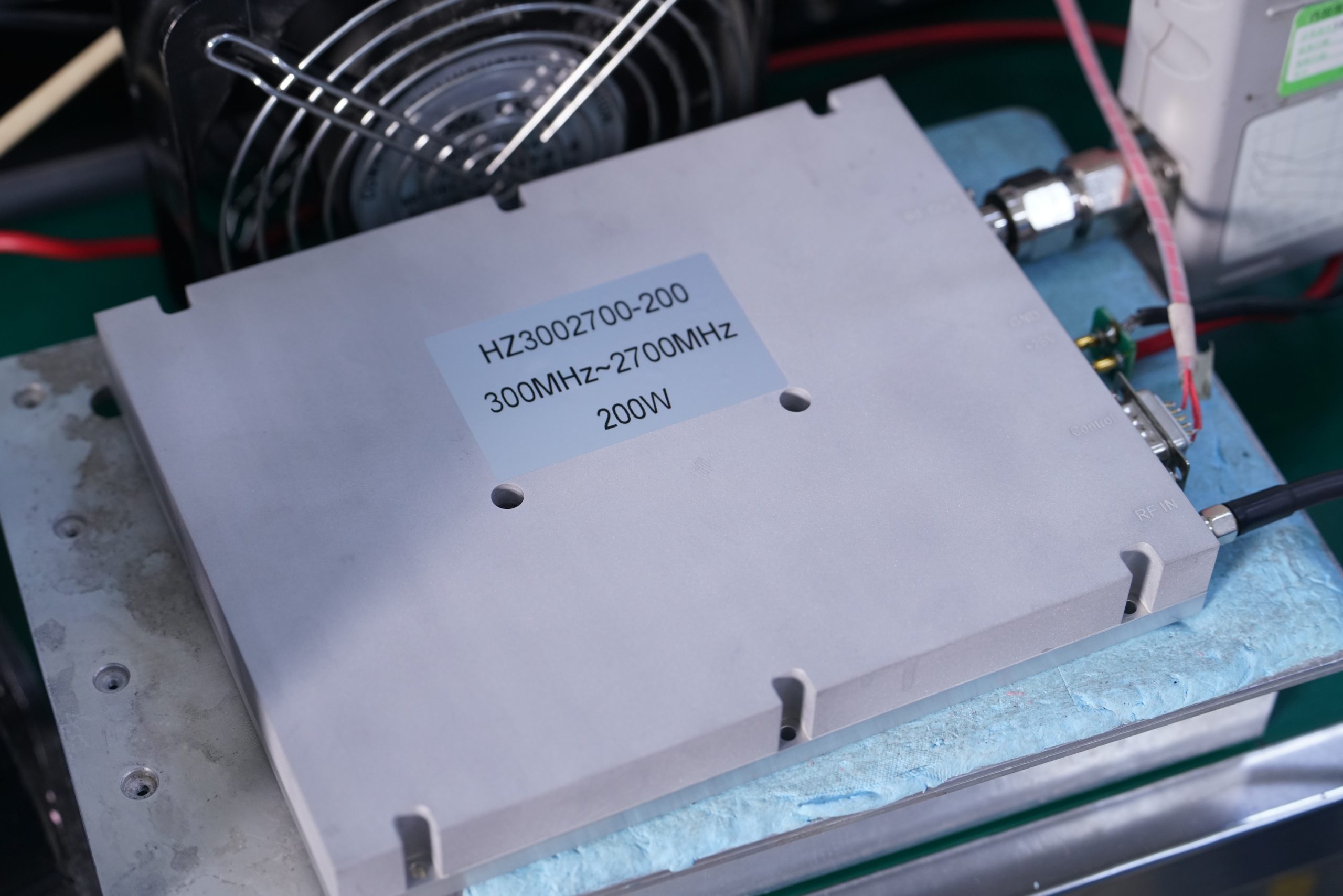
A wideband high-power RF PA test should prove more than whether the amplifier reaches its rated output at one frequency.
A strong power reading may still leave several approval questions unanswered. The input match may vary across the operating band. The required drive level may be unclear. The displayed output may not be corrected to the PA connector. Harmonic behavior may change near rated power. A short cold-state result may also fail to represent sustained operation after heat builds up.
Rated power identifies an output class. Shipment approval requires traceable evidence across the RF input, PA output, DC supply, cooling condition, spectral behavior, protection state, and serial number of the delivered module.
1. Why Rated Power Is Only the Start of RF PA Approval
A rated output value does not describe the complete operating window of a wideband high-power amplifier.
Before using a power figure for project approval, the buyer should determine whether it represents:
- a minimum specified output;
- a typical output value;
- a result from one frequency;
- a short-duration measurement;
- or sustained continuous-wave operation.
These descriptions are not interchangeable.
A typical power value should not automatically become the minimum project requirement. A center-frequency result should not be treated as full-band evidence. A short measurement should not represent output after the amplifier has reached its normal hot-state condition.
Every usable output result should be connected to:
- tested frequency;
- actual power at the PA input connector;
- corrected power at the PA output reference plane;
- DC voltage at the PA terminals;
- operating current;
- load condition;
- cooling method;
- operating duration;
- and thermal state.
Frequency coverage also needs a defined boundary.
If the complete catalog bandwidth is being approved, testing should include representative frequencies and relevant band edges. If the amplifier will operate only within assigned project bands, the approval test should at least cover every required frequency and any points where gain, output, efficiency, or thermal margin may be more demanding.
Supply and cooling conditions are equally important. A module operating on an adequate laboratory heatsink may not behave the same way inside a restricted cabinet with warmer inlet air, reduced airflow, voltage drop, or recirculated heat.
For this reason, RF Power Amplifier Modules should be reviewed through defined input, output, load, thermal, and evidence boundaries rather than rated watts alone.
2. What a Complete Factory Test Sequence Should Establish
A complete factory test sequence should move from the small-signal baseline to high-power output, spectral behavior, and shipment evidence. Each stage answers a different approval question.
The process normally begins with a small-signal gain sweep. This measurement shows how amplification changes across the required frequency range and helps identify local dips, unusual variation, or differences between tested units.
Input VSWR is then checked at the PA input connector. This confirms whether the amplifier presents an acceptable match to the signal source, SDR, or driver. It does not describe the matching condition of the output cable, filter, feeder, or antenna.
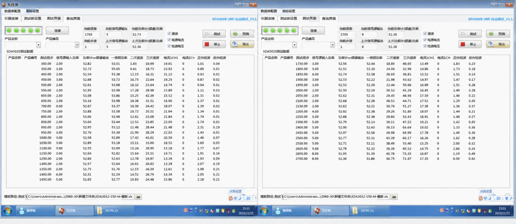
After the input baseline has been established, the test moves to high-power operation. Actual input power must be defined at the PA input reference plane, while output power must be corrected to the PA output reference plane.
Spectral verification is performed under the defined high-power condition. The fundamental output, harmonics, and non-harmonic spurious signals should be measured through a calibrated sample path and compared with their applicable limits.
These stages answer four separate questions:
- Does gain remain within its specified range across the required frequencies?
- Does the PA input provide an acceptable match to the source or driver?
- Can the amplifier deliver the required output under the defined RF, DC, load, cooling, and duration conditions?
- Does the output spectrum remain within the required harmonic and spurious limits near rated power?
One factory test example uses a 300–2700 MHz, 200 W wideband module. The process includes a VNA gain sweep, an input-VSWR check, and a transition to output-power and harmonic testing.
The same approval logic applies to other wideband high-power frequency ranges and output classes. Test frequencies, drive levels, output targets, cooling conditions, and acceptance limits may change, but the evidence categories remain separate.
Completing the measurement sequence does not automatically complete shipment approval. The final package must connect each result to recorded conditions, correction values, applicable limits, and the serial number of the actual module being shipped.
3. Why Gain and Input VSWR Need Separate Small-Signal Verification
Small-signal gain and input VSWR establish the amplifier’s input baseline before high-power behavior is evaluated.
The gain sweep shows how much the PA amplifies an input signal and how that amplification changes with frequency. This helps the integrator estimate an initial SDR or driver range and identify frequency points that may require closer review.
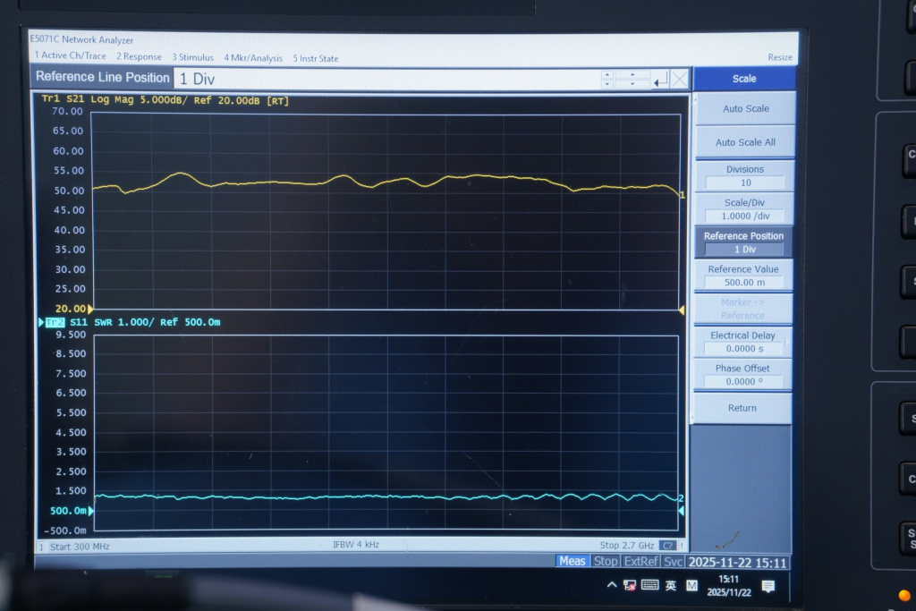
Small-signal gain cannot determine the final full-power drive requirement by itself.
Near rated output, the required input may change because of:
- gain compression;
- operating frequency;
- supply voltage;
- temperature;
- output target;
- and unit-to-unit variation.
Final input power must therefore be confirmed during the high-power test.
A gain trace that appears normal at a low VNA input level does not prove that the amplifier reaches its rated output. It establishes small-signal transfer behavior under the recorded sweep condition.
Input VSWR answers a different question: how well does the PA input accept energy from the source or driver?
A poor input match can reflect part of the drive signal back toward the source. This may reduce the power entering the amplifier and make the signal-generator display a misleading indicator of actual PA input power.
The measured input VSWR for one tested unit may be better than the specified product limit. That unit-level result can be recorded in its report, but it should not replace the formal limit applied to the product or shipment.
Input VSWR must also remain separate from output-path VSWR. The PA input measurement does not prove the matching condition of the output cable, filter, feeder, connector, or antenna.
High-power behavior requires a separate swept-frequency full-power RF PA test under the required output, supply, load, cooling, and duration conditions.
4. Why Input and Output Reference Planes Change Every Result
The signal-generator display is not automatically the RF power delivered to the PA input connector. The analyzer display is also not automatically the corrected output at the PA connector.
A reference plane is the physical point where a measurement is defined.
For amplifier testing, the two most important reference planes are normally:
- the PA input connector for actual input power;
- the PA output connector for corrected amplifier output.
Between the generator and PA input, the source path may contain cables, adapters, switches, attenuators, couplers, connectors, or a driver stage.
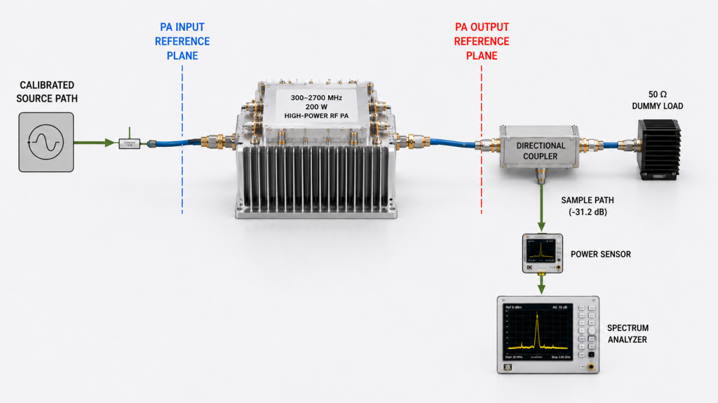
Each component can add gain or loss, and that value may change with frequency. All calibrated source-path gain and loss must therefore be included when actual input power is calculated.
An incorrect input reference can create:
- a false gain calculation;
- an incorrect driver requirement;
- an unfair comparison between modules;
- or a misleading relationship between input and output power.
A usable input record should identify:
- signal-generator setting;
- source-path gain and loss;
- actual power at the PA input connector;
- frequency-dependent correction;
- calibration date and validity;
- and the defined input reference plane.
The same principle applies at the output.
A spectrum analyzer or power sensor cannot normally accept the direct output of a high-power amplifier. A directional coupler, attenuator, adapter, and cable reduce the sampled signal to a safe measurement level.
The complete sample-path correction must be applied before the result is reported at the PA output reference plane.
The report should distinguish between:
- the level displayed by the instrument;
- the total correction applied to the sample path;
- and the corrected result at the PA output connector.
Without this separation, two laboratories may report different output or harmonic values even when the amplifier itself has not changed.
5. Why Reaching Rated Power Does Not Complete the Spectrum Check
Reaching the required RF output does not complete approval. Harmonic and spurious behavior must also be measured at the defined high-power operating condition.
The fundamental is the intended RF output. The second harmonic appears at twice the fundamental frequency, while the third harmonic appears at three times the fundamental frequency.
Non-harmonic spurious signals are unwanted outputs that do not follow those simple multiples.
A PA may show acceptable small-signal behavior while producing different harmonic or spurious levels near rated continuous-wave output. Spectral performance should therefore be measured at the required high-power state rather than inferred from a VNA trace.
A useful spectral record should include:
- fundamental frequency;
- corrected fundamental power at the PA output reference plane;
- harmonic or spurious frequency;
- corrected unwanted-signal level;
- calculated result in dBc;
- sample-path correction;
- applicable limit;
- equipment configuration and calibration validity;
- and pass-or-fail conclusion.
The unit dBc expresses an unwanted signal level relative to the fundamental output. Harmonics and non-harmonic spurious signals are separate acceptance items and should not be combined into a general statement such as “the spectrum is normal.”
In the 300–2700 MHz, 200 W test example, the second- and third-harmonic limits are specified at −10 dBc, while non-harmonic spurious output is specified separately at −60 dBc under the defined 200 W continuous-wave condition. These values belong to that example and should not be applied automatically to another module or project.
One spectrum-analyzer screenshot at one frequency supports only the recorded frequency, power condition, correction state, and analyzer configuration. It cannot prove full-band spectral compliance.When harmonic acceptance depends on analyzer configuration, verify the RBW setting together with the signal type, detector or trace mode, input attenuation, declared reference plane, and frequency-specific correction before comparing marker results.
Instrument coverage also matters.
At a 2700 MHz fundamental, the second harmonic appears at 5400 MHz and the third harmonic at 8100 MHz. The analyzer, directional coupler, attenuator, cables, and calibration data must remain valid at those higher frequencies.
The same principle applies to any wideband high-power PA: the measurement path must cover the unwanted-signal frequency, not only the fundamental operating range.
6. Why Different RF PA Tests Must Stay Separate
Small-signal, high-power, harmonic, mismatch, and hot-state tests answer different approval questions. One result should not be used as a substitute for another.
A VNA gain trace cannot prove rated output. A high-power reading cannot prove input VSWR. One harmonic result cannot prove all spurious behavior. A cold-state result cannot prove sustained output after heat builds up.
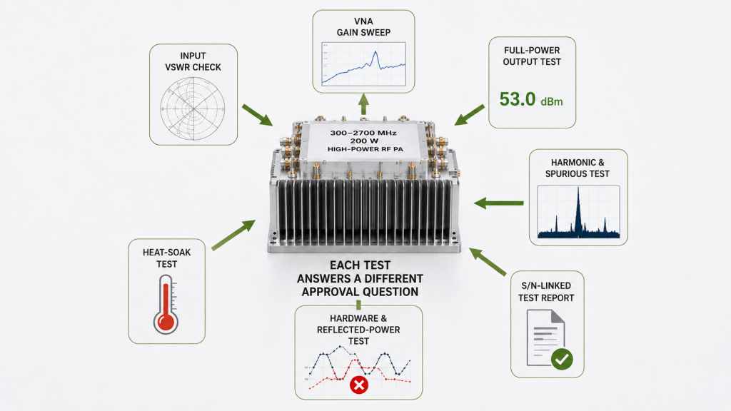
What Each Test in a Wideband High-Power RF PA Approval Process Proves
| Test shown or required | What it proves | What it does not prove |
|---|---|---|
| VNA gain sweep | Small-signal gain and frequency variation | High-power output |
| Input VSWR sweep | Matching condition at the PA input | Output-path or antenna VSWR |
| High-power test at recorded frequencies | Output capability at those frequencies and conditions | Performance at untested frequencies or conditions |
| Harmonic test | Harmonic level at the recorded frequency and power state | All spurious signals or full-band compliance |
| DC voltage and current record | Supply condition and DC input demand | Thermal stability |
| Hot-state test | Output, current, and protection behavior after heat accumulates | Cold-start behavior or full environmental qualification |
| Mismatch test | Reflected-power and protection behavior under the recorded mismatch | Normal high-power operation into a matched load |
| S/N-linked report | Results correspond to one tested module | Performance under every field installation |
Separate records also help distinguish test-path, supply, thermal, mismatch, and module-related causes during engineering review.
7. What Minimum Evidence Should Be Available Before Shipment
Shipment approval does not require the customer to define every laboratory setting. The supplier should convert the basic project requirements into a suitable test plan and provide enough evidence for the buyer to review the delivered module.
At minimum, the customer normally needs to provide:
- required operating frequency range or priority frequency points;
- minimum output requirement;
- available DC supply condition;
- expected operating duty;
- known cooling or installation constraints.
If a condition has not yet been finalized, it can remain project-defined and be reviewed during the RFQ stage.
The supplier should then define and record the relevant test frequencies, input drive, reference planes, load condition, operating duration, path corrections, and acceptance limits.
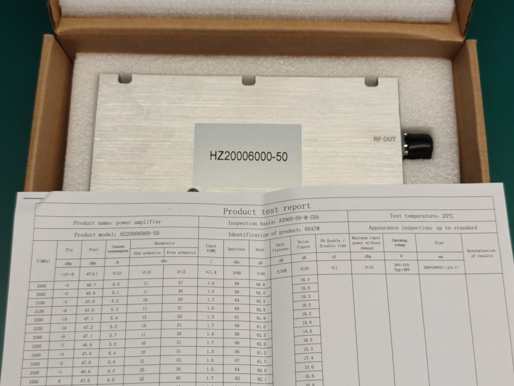
Minimum Shipment Evidence
A practical shipment test package should include:
- module model and serial number;
- tested frequency points;
- gain and input VSWR results;
- actual PA input power;
- corrected output power at the PA output connector;
- DC voltage and operating current;
- load and cooling conditions;
- harmonic or spurious results where required;
- test duration or thermal state;
- pass-or-fail conclusion.
Not every project requires the same test depth. A standard module may use an established factory test plan, while a custom frequency range, output target, cooling arrangement, or protection requirement may need additional evidence.
The most important point is traceability. The report should show which module was tested, under what conditions, and whether the recorded results meet the agreed project requirements.
A broader C-UAS RF PA acceptance checklist can be used when a project requires more detailed RF, thermal, protection, or mismatch verification.
Minimum RFQ Information
| RFQ item | Minimum information needed |
|---|---|
| Frequency requirement | Operating range or priority frequency points |
| Output requirement | Minimum required output at the PA connector |
| DC supply | Available voltage and current capacity |
| Operating condition | Continuous operation or project-defined duty |
| Cooling boundary | Available heatsink, airflow, or cabinet limitation |
| Special requirement | Any required harmonic, mismatch, protection, or reporting condition |
Once these basic conditions are available, the supplier can recommend the appropriate test scope instead of requiring the customer to prepare a complete laboratory specification.
A C-UAS RF PA module selection review can then consider frequency coverage, input drive, DC capacity, cooling, antenna path, protection behavior, and the level of shipment evidence required for the project.
Conclusion
A complete wideband high-power RF PA test must connect output performance to frequency, input and PA-output reference planes, DC condition, cooling state, spectral limits, protection behavior, and serial-number traceability.
Each test answers a different approval question and should remain separate in the shipment report.
Send RF SKYPOWER your required frequency points, minimum output at the PA output reference plane, available input drive, DC supply condition, cooling boundary, load condition, spectral limits, and shipment evidence requirements for an early engineering review before final module approval or RFQ.