










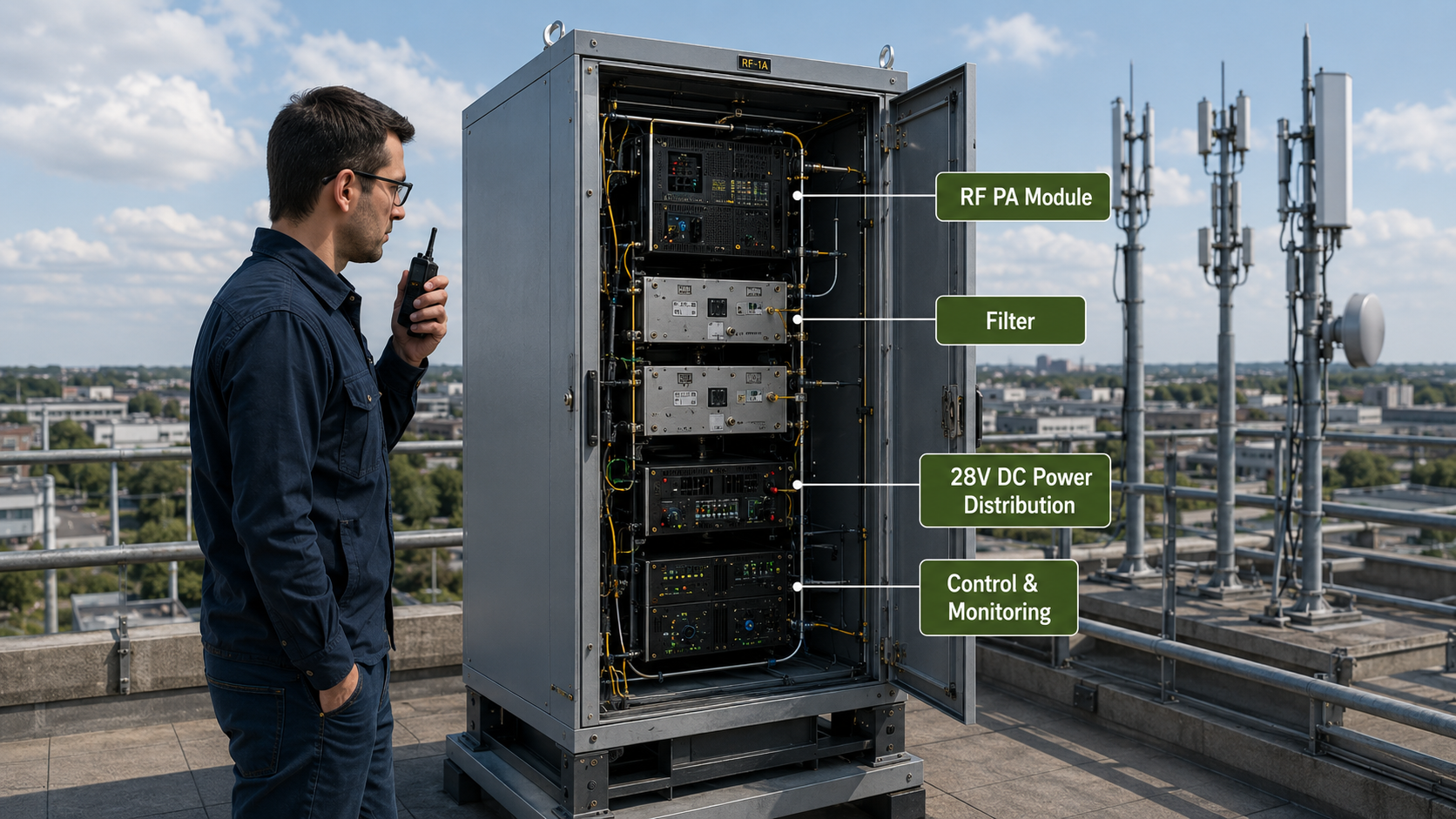
C-UAS interference can occur even when a system covers every required target frequency. Internal radios may lose clarity, telemetry links may become unstable, or site Wi-Fi may stop working when one or more RF channels are enabled.
This type of C-UAS communication interference cannot be prevented by confirming frequency coverage alone. The project must distinguish between the full frequency range the hardware can support, the narrower operating windows that may be enabled, and the communication channels that must remain available during operation.
Target-band output and protected-band compatibility are separate acceptance results. Both must be verified under the same defined operating condition.
1. Why a Wider Supported Frequency Range Creates More Integration Risk
A wider supported frequency range can improve system flexibility, but it also increases the number of existing communication services that must be reviewed before deployment.
Three terms must remain separate:
- Supported frequency range: the full frequency range the SDR, RF PA, filtering and antenna architecture can support.
- Occupied bandwidth: the width of the signal produced during a specific operating mode.
- Geographic coverage: the physical area in which the installed RF system produces the required field level.
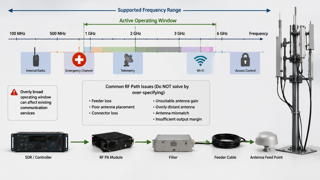
A system may support a wide frequency range while transmitting within only a limited occupied bandwidth at any given time. Wide hardware capability does not mean the complete supported range should be active simultaneously.
Integration risk increases when an overly broad operating window is used to compensate for another problem, such as:
- Feeder loss
- Poor antenna placement
- Unsuitable antenna gain
- Cabinet obstruction
- Antenna mismatch
- Insufficient output margin
Broadening the active spectrum may expose more existing services without correcting the original RF-path problem.
Potentially affected systems can include internal handheld radios, emergency channels, Wi-Fi, telemetry, access control and nearby licensed services.
The problem is therefore not that wideband RF hardware is unsuitable. The correct engineering conclusion is that a wider supported frequency range requires more precise operating-window control, protected-band limits and acceptance evidence.
2. Separate Target Bands from Protected Bands Before PA Selection
Preventing C-UAS communication interference begins with two frequency lists.
Target bands are the project-defined frequency windows the system must support.
Protected bands are communication frequencies that must remain available, or remain below an agreed RF-output limit, while the C-UAS RF chain is operating.
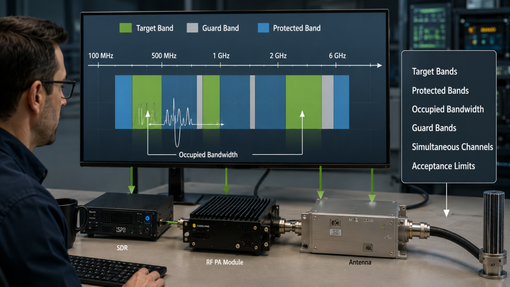
Protected bands may include:
- Internal guard radios
- Emergency communication channels
- Wi-Fi
- Telemetry
- Access-control systems
- Nearby licensed services
- Other RF equipment at the facility
These services may require different acceptance limits. An emergency radio channel may need a stricter boundary than a non-critical local network.
The frequency plan should also define a guard band, meaning the frequency separation kept between an active operating window and a protected channel. This margin may be required because of filter transition width, waveform bandwidth, frequency tolerance, switching behavior and measurement uncertainty.
| Planning item | What the engineer must define | Risk if omitted |
|---|---|---|
| Supported frequency range | Full hardware frequency capability | Hardware capability may be confused with the approved operating range |
| Target band | Exact frequency window required for each mode | Required coverage may contain gaps |
| Occupied bandwidth | Actual signal width for each waveform | The active spectrum may be wider than expected |
| Protected band | Frequencies that must remain available | Internal or nearby communications may be affected |
| Guard band | Required separation from protected channels | Filter transition or waveform energy may cross the intended boundary |
| Acceptance limit | Maximum permitted RF level and communication-availability requirement | “No interference” cannot be objectively approved |
| Site verification points | Frequencies, operating modes and physical locations to be checked | A laboratory result may not represent the installed system |
An RFQ that lists only broad ranges such as 400–500 MHz, 800–900 MHz, 2.4 GHz or 5.8 GHz still leaves important questions unanswered.
Before selecting RF Power Amplifier Modules, the integrator should state:
- Which frequency windows must be active
- Which frequencies must be excluded
- The maximum occupied bandwidth
- The required guard bands
- Which RF channels may operate simultaneously
- Which protected frequencies require site verification
These conditions may change the SDR setup, PA architecture, filter design, number of RF channels, control sequence and antenna arrangement.
3. Why an SDR Notch Does Not Prove the Final RF Boundary
A frequency exclusion configured in the SDR must still be verified after amplification.
The conducted RF path may include:
SDR output → Driver → RF PA → Filter → Connector → Feeder → Antenna
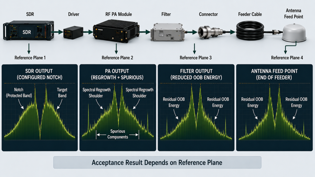
An SDR screen can confirm that a frequency window, bandwidth limit or notch has been commanded. It does not prove the output condition at the PA connector, filter output or antenna feed point.
The RF PA does not normally move the commanded signal to another frequency. However, unwanted energy can appear outside the intended operating band because of several effects:
- Spectral regrowth: signal energy spreading beyond the intended waveform bandwidth when the amplifier is driven too close to compression.
- Harmonic output: unwanted energy appearing at multiples of the operating frequency.
- Spurious output: unintended signals that are not part of the required waveform.
- Multi-channel intermodulation: new unwanted frequencies created when several amplified signals interact.
- Switching transients: brief RF bursts that may appear during enable, mute or channel changes.
- Thermal or load-related changes: output behavior changing as the PA heats up or sees an abnormal antenna load.
The filtering stage then adds its own passband, stopband and transition region. Filter rejection must be reviewed at the actual waveform, frequency, RF power, temperature and load condition.
Feeders, adapters and antennas do not normally create the original out-of-band signal. They can, however, change frequency-dependent loss, return loss and the load seen by the PA.
Passive intermodulation may also become relevant. This means unwanted frequencies are created at poor, loose, contaminated or unsuitable passive connections when several high-power signals are present.
Verification must therefore identify an exact measurement reference plane.
Conducted measurement points may include:
- SDR output
- PA output connector
- Filter output
- Antenna feed point
Installed-site verification points may include:
- A defined over-the-air monitoring location
- A representative internal-radio operating area
- A specified distance and antenna orientation
- An accessible protected-receiver input
- A site location where communication availability must be maintained
Conducted spectrum evidence and installed-site coexistence evidence answer different questions. A clean PA-port measurement can prove conducted output quality, but it does not automatically prove that an internal radio remains usable after the complete antenna system is installed.
4. How SDR, RF PA, Filtering and Control Create One Operating Boundary
Protected-band control is a system result. It cannot be assigned to the SDR or RF PA alone.
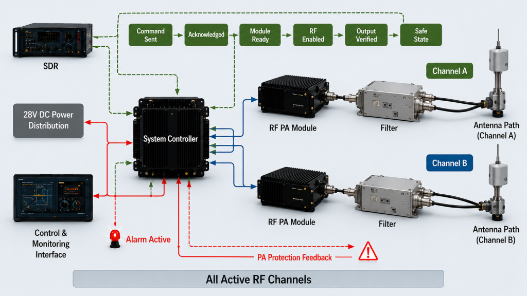
The SDR generates the required signal and applies the configured frequency, waveform, occupied bandwidth, gain and mute state.
The RF PA amplifies the signal presented at its input. It must provide the required target-band output, respond correctly to enable and mute commands, and enter a controlled state when voltage, temperature or reflected-power limits are exceeded.
The filtering stage limits unwanted output outside the approved operating window. Its passband, transition region, rejection and power handling must match the actual project condition.
The control system coordinates when each RF function becomes active. It should distinguish between:
- Command sent
- Command acknowledged
- Module ready
- RF enabled
- Output verified
- Alarm active
- Safe state confirmed
These states are not interchangeable.
A controller may receive a valid frequency acknowledgement while one RF channel remains in its previous state. A mute command may be accepted before the amplified output has fully stopped. An alarm may disable one PA while the main interface still reports the overall system as active.
The control specification should therefore define:
- Command sequence
- Enable and mute timing
- Ready and RF-output feedback
- Alarm response
- Communication timeout
- Restart behavior
- Required safe state
Multi-channel operation must also be tested as a combined condition. Two channels that pass separately may produce intermodulation or a higher aggregate field level when enabled together.
For an architecture using unified 28 V DC power, AT-command control and several RF channels, the accepted spectrum boundary should be tied to a defined hardware, firmware and operating configuration. A change to one of these conditions may require the protected-band result to be reviewed again.
5. What Evidence Proves Internal Communications Remain Available
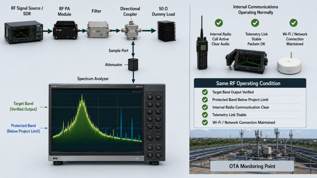
Preventing C-UAS communication interference requires two acceptance results under the same operating condition:
- The required RF output is present in the target band.
- The protected communication service remains within its approved RF and operational limits.
A valid test therefore needs both an RF acceptance limit and a communication-availability criterion.
Define the RF acceptance limit
The protected-band limit may be expressed as:
- Maximum conducted output in dBm at a defined connector or reference plane
- A relative level in dBc, meaning how far the unwanted signal is below the required carrier
- Field strength in dBµV/m at a defined distance and location during an over-the-air measurement
- Maximum permitted level at an accessible protected-receiver input
- Project-defined limits for harmonics, spurious output or intermodulation
A value without a reference plane is incomplete. For example, −40 dBm at the PA output, antenna feed point and receiver input represents three different acceptance conditions.
The report should record the analyzer frequency span, bandwidth settings, detector and trace mode, attenuation or correction values, and exact measurement reference plane. Without these settings, two spectrum plots may look similar while representing different measurement conditions.
Define communication availability
The acceptance method should match the protected service.
For an internal radio network, evidence may include:
- Successful call completion
- Acceptable voice intelligibility
- SINAD, a measurement of received signal quality relative to noise and distortion
- Receiver signal or quality data defined by the project
For digital communication, evidence may include:
- Packet or bit error rate
- Telemetry packet success
- Wi-Fi connection retention
- Minimum required throughput
- Access-control or alarm response
Not every project requires every metric. The customer and integrator should agree in advance on what “communication remains available” means for each protected service.
The target-band and protected-band checks must use the same defined RF operating state. Measuring target output at full power and then checking the protected band after the RF channel has been muted does not prove coexistence.
The test plan should cover the conditions most likely to change the result:
- Required frequency windows
- Maximum occupied bandwidth
- Individual RF channels
- Simultaneous channel modes
- Enable, mute and switching transitions
- Cold-state operation
- Hot-state operation after thermal stabilization
- Relevant alarm or protection states
- Installed antenna and feeder configuration
This distinction became important in a high-security facility integration case, where the required RF operating windows had to be reviewed alongside an existing 400 MHz internal radio network. The integration combined frequency exclusions, spectrum verification, unified power and system-level control rather than treating the SDR notch as sufficient evidence.
Test evidence must also remain traceable after delivery. A report linked to the unit serial number, firmware version and configuration revision helps the customer confirm that the delivered equipment matches the accepted condition. The same principle applies to RF power amplifier test-report version control.
6. How to Write Communication Conflict Checks into the RFQ
The RFQ should define protected communication bands before the SDR configuration, RF PA architecture and filtering plan are approved.
The RFQ does not need to contain a completed RF design. It must, however, provide enough information to identify possible conflicts and define how the final result will be accepted.
RFQ Checklist
| RFQ item | Customer input needed | What it confirms |
|---|---|---|
| Target frequency windows | Exact start and stop frequency for each operating mode | What the system must support |
| Protected communication bands | Internal radio, Wi-Fi, telemetry, access-control and licensed-service frequencies | What must remain available |
| Occupied bandwidth | Waveform bandwidth for each mode | How wide the active signal may be |
| Guard bands and exclusion limits | Required separation and maximum permitted RF level | The protected-band boundary |
| SDR operating condition | Waveform, frequency, gain and output level | The signal presented to the driver or PA |
| RF PA condition | Required frequency, usable output, duty cycle and channel mode | The amplified operating state |
| Filter requirement | Passband, transition region, rejection and power condition | Whether the exclusion boundary can be maintained |
| Simultaneous-channel modes | RF channels that may operate together | Combined spectrum and intermodulation risk |
| Antenna and feeder path | Antenna type, feeder length, connectors, filters and installation layout | How the installed path differs from the bench setup |
| Measurement method | Reference plane, analyzer settings, RF limits and OTA locations | How the spectrum result will be measured |
| Communication verification | Required radio, telemetry, Wi-Fi or control-system criteria | How protected-service availability will be judged |
| Configuration traceability | Serial number, firmware, settings, test date and report revision | Which delivered configuration produced the accepted result |
The RFQ should not rely on a general statement such as “no interference permitted.” The customer and supplier should agree on:
- What will be measured
- Where the measurement will be taken
- Which system mode will be active
- Which RF limit will apply
- How communication availability will be judged
- Which records must appear in the final report
The installed RF path should also be reviewed before approval. Feeder loss, connector condition, antenna mismatch and installation layout can change the load and field result even when the PA passed a laboratory test. These checks can begin with the conditions described in how to check an RF power amplifier load before integration.
RF SKYPOWER can support an early engineering review of the target frequencies, protected bands, SDR operating condition, PA output requirement, filter boundary, control interface, antenna path and required evidence format.
Conclusion
Wide C-UAS frequency capability does not automatically create a controlled operating spectrum.
The common mistake is to approve target-band coverage without separately defining the communication channels that must remain available. Preventing C-UAS communication interference requires the SDR, RF PA, filtering, control timing and installed antenna environment to be verified as one system.
Before RFQ, prepare the target frequency windows, occupied bandwidth, protected bands, guard bands, simultaneous operating modes, measurement reference planes, communication-availability criteria and report-traceability requirements.
To review these conditions before the SDR configuration and RF PA architecture are finalized, contact RF SKYPOWER.