








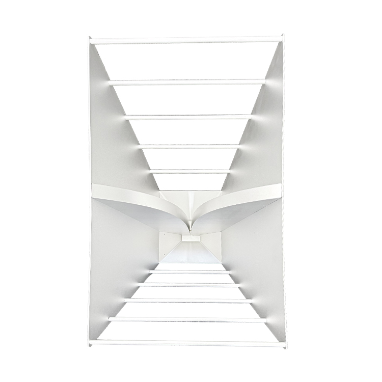
FIXED SECTOR / DIRECTIONAL
Concentrate RF energy toward a known sector, perimeter segment, route, or other defined coverage direction.


High-performance systems engineered for consistent, dependable operation under critical conditions.
See It in Action
High-performance systems engineered for consistent, dependable operation under critical conditions.
See It in Action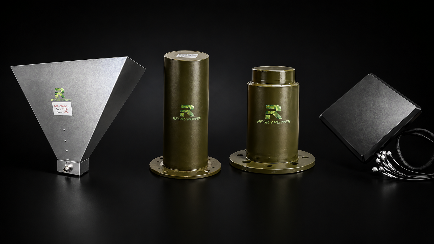
A C-UAS antenna should not be selected only because its frequency range overlaps with the RF PA and its listed maximum input power appears sufficient.
Those specifications are important, but they do not show how much gain is available at each required frequency. They also do not show where the RF energy will go or whether the antenna architecture matches the number of PA channels in the system.
A horn antenna concentrates energy toward a defined sector. An omnidirectional antenna supports broad horizontal coverage. A multi-port panel integrates several band-specific antenna channels into one external structure.
These antennas do not provide the same coverage through different shapes. They solve different RF distribution and system-integration problems.
A reliable selection process should connect:
Gain → Beamwidth → Radiation Pattern → Power Handling → VSWR → Polarization → Connector → Mounting → Antenna-Input Target
The correct starting point depends on the target frequencies, PA output per channel, coverage geometry, feeder path, installation location, and required acceptance evidence.
Frequency range indicates where an antenna is intended to operate. It does not prove that the antenna provides the required gain, beamwidth, impedance match, or power handling at every frequency inside that range.
For example, a horn described as covering 300–2700 MHz may support several C-UAS bands. Its measured gain can still differ significantly between 400 MHz, 1300 MHz, and 2700 MHz.
The same principle applies to a broadband omni antenna. One specified gain value does not prove that the same result is available across the full operating range.
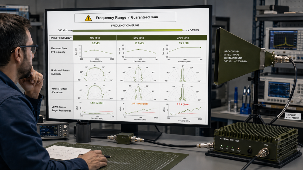
Frequency overlap between the RF PA and antenna is therefore only the first check.
The selection review should also determine:
Antenna frequency coverage shows where the antenna may operate. It does not show how much usable gain, beam control, or power handling is available at each required frequency.
The three antenna architectures support different C-UAS coverage and integration strategies.
FIXED SECTOR / DIRECTIONAL
Concentrate RF energy toward a known sector, perimeter segment, route, or other defined coverage direction.

MOBILE / 360-DEGREE AZIMUTH
Distribute RF energy around the horizontal plane when the threat direction is not fixed or antenna steering is impractical.

MULTI-CHANNEL / BAND-SPECIFIC PORTS
Combine several band-specific radiating elements and RF inputs in one coordinated external structure.
Antenna gain is often reduced to one prominent number on a product card.
That number may represent:
These descriptions are not interchangeable.
HARDWARE REFERENCE
Frequency coverage identifies the operating span. It does not prove one constant gain value or one fixed beam shape across that span.
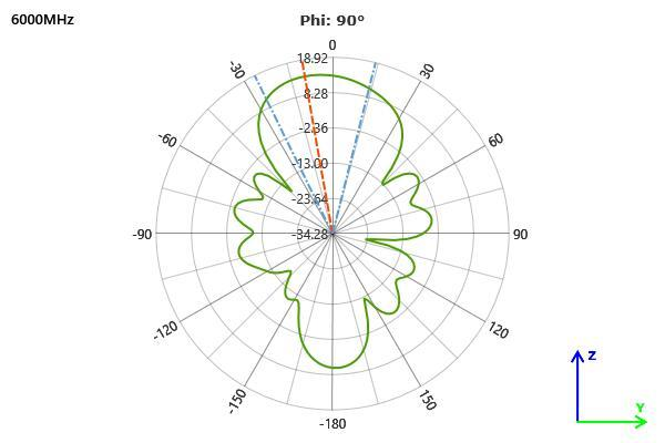
PATTERN AND BEAMWIDTH EVIDENCE
Gain, horizontal and vertical patterns, beamwidth, side radiation, and rear radiation should be checked at the frequencies used by the project.
| Evidence Item | 300–2700 MHz Horn | 2000–6000 MHz Horn |
|---|---|---|
| Available Measured Range | 2.2 to 16.19 dBi in the available 400–2700 MHz data | Approximately 13.16 to 19.07 dBi in the available report |
| Highest Reported Value | 16.19 dBi at 1300 MHz | Approximately 19.07 dBi near 4000 MHz |
| Lower-Gain Example | 2.2 dBi at 400 MHz | Approximately 13.16 dBi near 5600 MHz |
| Correct Interpretation | Do not present the 1300 MHz peak as full-band gain. The available table starts at 400 MHz, so a 300 MHz value should not be inferred. | Review the measured gain and horizontal/vertical patterns at the project frequencies, including the band edges. |
| Frequency | 400 MHz | 800 MHz | 1000 MHz | 1300 MHz | 2000 MHz | 2700 MHz |
|---|---|---|---|---|---|---|
| Measured Gain | 2.2 dBi | 7.05 dBi | 11.27 dBi | 16.19 dBi | 13.79 dBi | 15.68 dBi |
Selection rule: Treat peak, specified, typical, and frequency-specific measured gain as different evidence categories. The target-frequency result is the one that matters to the deployment.
A peak gain value can look impressive while hiding much lower gain at another frequency that matters more to the deployment.
A horn antenna may be a strong starting point when the C-UAS deployment requires controlled directional energy.
It can be considered when:
The main advantage is not simply a larger gain number. It is the ability to control the coverage direction.
A narrower beam can concentrate energy into a smaller angular region. A wider beam can cover a broader sector. The correct choice depends on distance, sector width, mounting height, and the required overlap between adjacent antennas.
300–2700 MHz / LOW-TO-MID-BAND
A broader low-to-mid-band directional starting point with a 250W listed maximum input-power boundary.
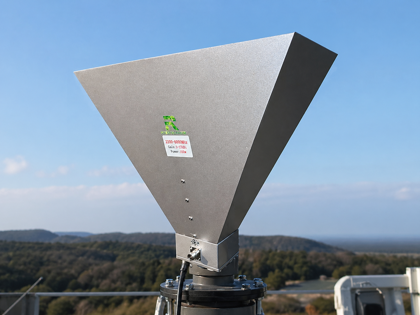
2000–6000 MHz / HIGH-BAND
A smaller and lighter high-band directional starting point with a 100W listed maximum input-power boundary.
| Review Item | 300–2700 MHz Horn | 2000–6000 MHz Horn |
|---|---|---|
| Directional Starting Point | Broad low-to-mid-frequency sector coverage | Higher-frequency sector coverage |
| Approximate Size | 540 × 300 × 430 mm | 450 × 230 × 415 mm |
| Approximate Weight | 2.5 kg | 2 kg |
| Polarization | Vertical | Vertical |
| Connector | N-K listed in the current specification | Confirm the approved connector configuration before RFQ |
| Listed Maximum Input Power | 250W | 100W |
| Evidence Required | Target-frequency gain, horizontal and vertical patterns, beamwidth, VSWR, feeder loss, and actual forward power | Target-frequency gain, horizontal and vertical patterns, beamwidth, VSWR, feeder loss, and actual forward power |
Before approval: Compare the listed antenna input-power boundary with the measured forward power at the antenna input, not only with the nominal PA rating.
These differences affect mounting space, support structure, cable routing, wind exposure, PA matching, and installation angle.
For example, a 200W PA channel should not be approved with an antenna carrying a 100W listed input boundary until the actual forward power at the antenna input and the operating conditions have been reviewed.
That review should form part of the wider C-UAS RF PA selection, because PA-port output and antenna-input power are not automatically the same value.
A horn antenna is a strong starting point when the project needs controlled directional energy, provided its measured gain and beam shape are suitable at every target frequency.
An omnidirectional antenna may be considered when the system needs broad horizontal coverage and the threat direction is not fixed.
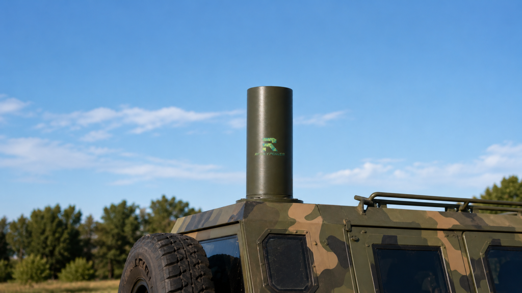
Typical starting conditions include:
The main advantage is that the antenna does not need to be pointed toward one fixed horizontal direction.
However, omnidirectional does not mean equal performance in every direction in three-dimensional space.
The horizontal pattern provides broad azimuth coverage. The vertical pattern still determines how much energy travels near the horizon and how coverage changes above or below the antenna.
Mounting height, the supporting metal structure, nearby antennas, ground-plane conditions, and cable routing can also alter the installed pattern.
An omni antenna that performs well in a controlled setup may therefore produce a different field pattern after installation on a vehicle, rooftop, mast, or metal cabinet.
The 380–3000 MHz and 400–6000 MHz omni antennas currently list 9 dB specified gain. The 800–2600 MHz version lists 5.5 dB specified gain.
These values provide selection starting points. They should not be interpreted as proof that every frequency inside each band produces the same measured gain.
The project should request target-frequency data, especially near the band edges.
A useful omni review should connect:
An omnidirectional antenna supports broad horizontal coverage, while its vertical pattern, mounting conditions, and frequency-specific performance determine where the RF energy actually goes.
A multi-port panel can simplify the external antenna arrangement of a multi-channel C-UAS system.
Instead of mounting several separate antenna bodies, multiple band-specific radiating elements can be integrated into one coordinated panel structure.
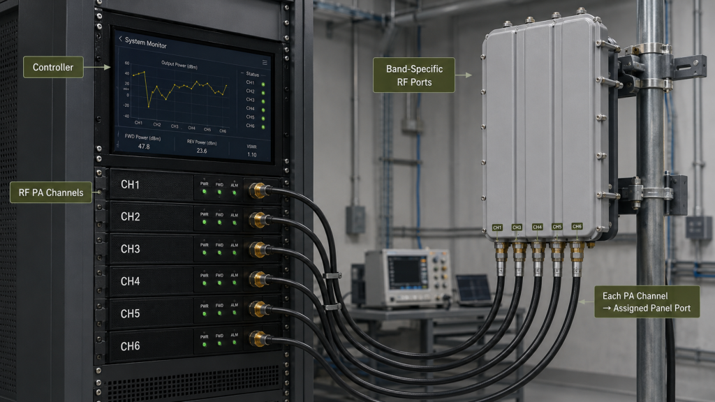
This architecture can provide:
It may be a useful starting point when the RF system already divides its output into separate band-specific PA channels.
Each PA channel should connect to the panel port assigned to its operating band.
The mapping should be controlled through:
This creates a clear relationship between the controller, PA channel, cable, connector, and antenna element.
The panel includes approximately 1.5 m RG195 feeder sections.
Their insertion loss changes with frequency. That loss should be included when calculating the forward power available at each antenna port.
For each channel, the power path should be recorded as:
PA-port output → Cabinet and connector loss → External feeder loss → Panel feeder loss → Available forward power at the assigned antenna port
The current panel specification lists a 50W maximum input-power value, but it does not clearly state whether that limit applies to each port, selected ports, or the complete assembly.
The RFQ should therefore define:
These interface definitions allow the panel’s mechanical and channel-integration advantages to be used correctly.
A multi-port panel can simplify the external antenna structure while supporting several band-specific PA channels through one coordinated mechanical assembly.
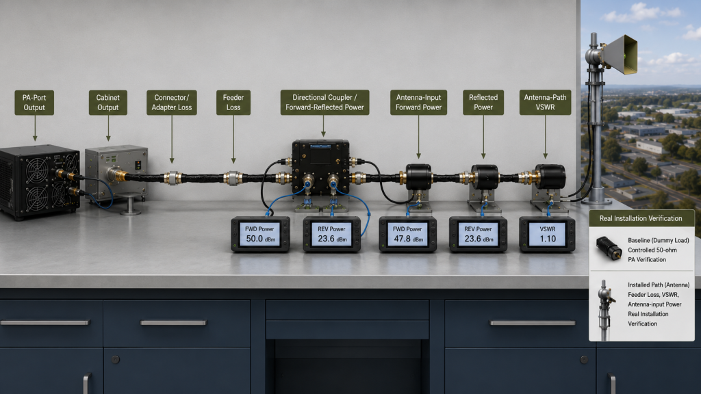
A C-UAS antenna should be approved as part of the complete PA-to-feeder-to-antenna path, not as an isolated frequency-range product.
The first decision is the required coverage geometry:
The next step is to confirm which antenna architecture supports that geometry at the required frequencies and power levels.
| Selection question | Horn | Omni | Multi-Port Panel |
|---|---|---|---|
| Primary coverage goal | Directional sector | Broad horizontal coverage | Several predefined frequency bands |
| RF distribution | Concentrated toward a selected direction | Distributed around the horizontal plane | Distributed through separate band-specific ports |
| Gain behavior | Often higher but frequency-dependent | Specified or measured gain varies by frequency | Different gain by port |
| Input architecture | Usually one broadband input | Usually one broadband input | Multiple independent RF inputs |
| Listed power boundary | 100W or 250W listed maximum input power, depending on model | Up to 250W listed maximum input power, depending on model | 50W maximum input power listed; exact boundary requires clarification |
| Main evidence | Frequency-specific gain and radiation patterns | Horizontal and vertical patterns | Per-port gain, VSWR, isolation, feeder loss, and power definition |
| Useful starting condition | Known direction or sector | Direction not fixed in the horizontal plane | Multiple band-specific PA channels |
The approval package should keep the following values separate:
When logarithmic units are used:
Available forward power at the antenna input (dBm) = measured PA or cabinet output power (dBm) − measured path insertion loss at the target frequency (dB)
When power is expressed in watts, path loss must be applied through linear transmission efficiency. A dB value must not be directly subtracted from a watt value.
Antenna mismatch should be evaluated separately through forward power, reflected power, return loss, or VSWR.
A dummy load can establish the RF PA baseline under a controlled load. The installed feeder and antenna path then confirm how the complete path behaves at the target frequencies. These two evidence levels should remain separate during dummy-load and real-antenna verification.
The RFQ should define:
The most useful question is not:
Which antenna has the widest frequency range?
It is:
Which antenna provides the required gain, beam shape, power boundary, impedance match, and channel architecture at every project frequency?
Choosing a C-UAS antenna is a coverage-geometry and RF-path decision, not only a frequency-range decision.
A horn antenna is a strong starting point when the system requires directional concentration toward a known sector. An omni antenna supports broad horizontal coverage when the direction is not fixed. A multi-port panel integrates several band-specific PA channels into one coordinated external structure.
The complete approval chain should connect:
PA output → Feeder loss → Antenna-input power → VSWR → Gain → Beamwidth → Radiation pattern → Installed coverage
For early engineering review, provide RF SKYPOWER with:
RF SKYPOWER can compare directional horn, broadband omni, and multi-port panel options against the actual PA channels, feeder path, mounting conditions, and coverage objective. Once those boundaries are defined, the required PA output, protection, control, cooling, and report package can also be reviewed through the Custom RF Power Amplifier Modules engineering process.
Contact RF SKYPOWER to review the C-UAS antenna architecture, frequency-specific gain, listed power boundary, feeder loss, VSWR, port mapping, and installation requirements before the antenna configuration is frozen.