











Low RF PA efficiency can increase DC and thermal burden, but a lower efficiency percentage does not automatically mean that an amplifier is unreliable.
A module with adequate electrical, cooling, and protection margin may remain stable, while another design can operate much closer to its limits under the same required RF condition.
That creates a more useful reliability question than simply comparing two efficiency percentages:
Which measured changes show that efficiency-related stress is materially reducing the PA’s operating margin?
Before approving the module, the evidence should separate efficiency-related burden from cooling limits, DC-path loss, load mismatch, protection behavior, and other conditions that can produce similar symptoms.
1. When Does Low RF PA Efficiency Become a Reliability Risk?
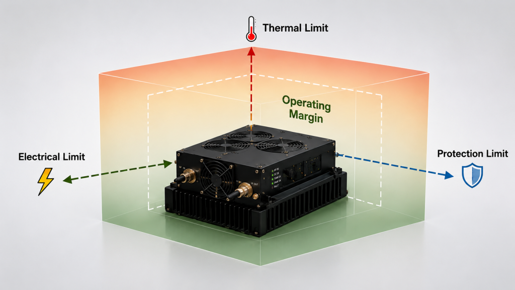
Efficiency becomes relevant to reliability when the additional electrical or thermal burden materially reduces the margin available for the required operating condition.
A lower efficiency number alone does not prove:
- shorter lifetime;
- excessive device temperature;
- unstable RF output;
- inadequate cooling;
- DC-path failure;
- or premature protection events.
Those conclusions require measurements at defined operating boundaries.
For a defined module DC-to-RF efficiency metric:
Efficiency = Pout,PA-port / Pdc,PA
For a PA with one regulated DC input representing the complete stated module boundary:
Pdc,PA = VPA × IPA
If multiple DC rails are included inside that boundary, the applicable DC input powers should be summed rather than represented by one V × I term.
A lower module DC-to-RF efficiency at the same corrected PA-port output generally requires more DC input power.
That additional burden matters when it reduces margin against:
- PA current limits;
- DC supply or converter limits;
- wiring and connector capability;
- thermal limits;
- derating thresholds;
- or protection boundaries.
The key reliability question is therefore not:
“Is the efficiency low?”
It is:
“Does the resulting electrical or thermal burden materially reduce the specified operating margin under the required conditions, even if short-term RF performance still appears acceptable?”
This is why headline efficiency percentages should not be compared without confirming the metric, operating point, DC boundary, and RF output reference plane.
2. How Do DC and Thermal Burden Reduce Reliability Margin?
Consider an illustrative module DC-to-RF efficiency example—not RF SKYPOWER product test data.
Suppose the required corrected PA-port output is:
Pout = 200 W
At 50% module DC-to-RF efficiency:
Pdc = 200 W / 0.50 = 400 W
At a regulated 28.0 V PA input:
Idc ≈ 400 W / 28.0 V ≈ 14.3 A
At 35% efficiency:
Pdc ≈ 200 W / 0.35 ≈ 571 W
Idc ≈ 571 W / 28.0 V ≈ 20.4 A
The RF output is the same, but the calculated module-side DC burden is substantially different.
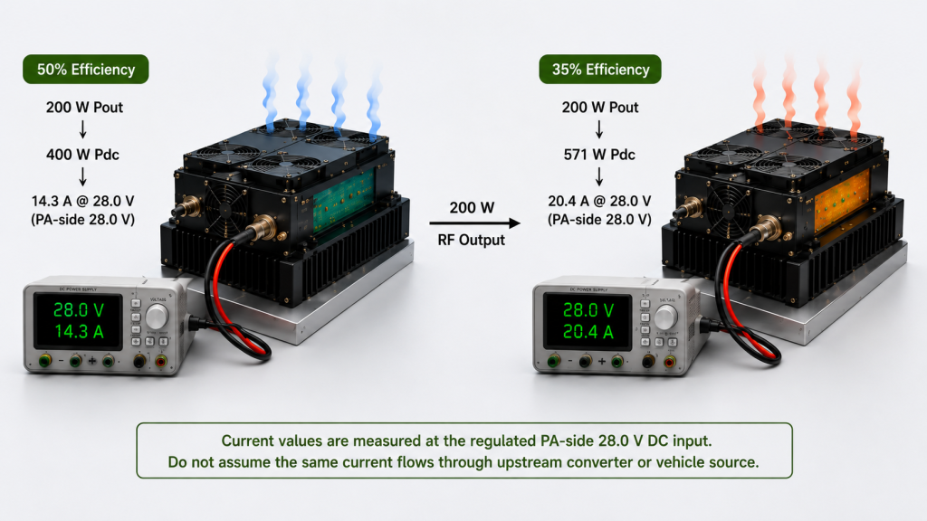
The 14.3 A and 20.4 A values apply only to the regulated 28.0 V PA-input boundary. Converter-input or upstream source current must be calculated or measured at its own voltage and efficiency boundary.
The higher PA-side demand can reduce margin in the converter, cabling, connectors, or shared DC path, but the same current value should not be transferred unchanged to an upstream boundary.
It also does not by itself prove reduced lifetime or identify the root cause of a field failure.
If the DC path is already close to its operating limit, review RF PA efficiency and DC power-supply stress separately rather than treating every current increase as a reliability failure.
What about heat?
Higher dissipation can reduce thermal margin, but efficiency alone cannot predict the resulting PA temperature.
Actual temperature depends on:
- RF output and efficiency metric;
- duty cycle;
- ambient or cabinet temperature;
- heatsink or cold-plate performance;
- airflow or liquid cooling;
- thermal resistance;
- mounting interface;
- and stabilization time.
For that reason, an undefined efficiency percentage should not be converted directly into a temperature or lifetime conclusion.
Use the defined electrical and RF boundaries in RF PA heat-load calculations when the actual thermal burden needs to be calculated.
The reliability decision depends on whether the measured electrical and thermal conditions leave adequate margin for the specified operating state—not only on whether the PA still produces the required Pout during a short test.
3. Which Operating Conditions Expose an Efficiency-Related Risk?
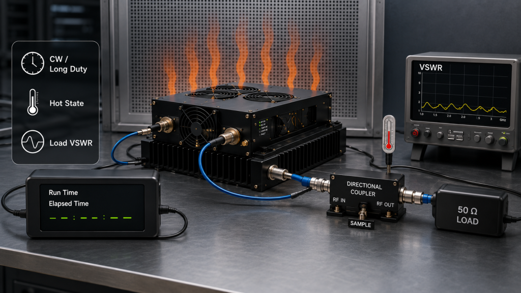
A short cold-state measurement can confirm one operating point, but it may not reproduce the condition in which electrical or thermal margin becomes smallest.
The most useful evidence normally comes from states that create sustained stress, such as:
- continuous or long-duty RF operation;
- stabilized hot-state operation;
- high ambient or cabinet temperature;
- the required waveform and duty cycle;
- reduced cooling margin;
- high load VSWR where specified;
- and simultaneous system loading.
For continuous operation, RF PA efficiency during CW operation should be verified at the required hot-state operating point rather than inferred from a short cold measurement.
Efficiency-Related Reliability Evidence
| Observation | What It May Indicate | What Must Be Checked Before Blaming Efficiency |
|---|---|---|
| Higher Idc | Higher DC burden | Pout, Vdc, efficiency metric, operating point |
| Higher temperature | Reduced thermal margin | Ambient, cooling, duty cycle, thermal interface |
| Hot-state Pout drift | Electrical or thermal margin loss | Pin, Vdc, Idc, temperature, load |
| Protection event | A monitored protection condition was triggered | Alarm threshold, DC path, load, temperature |
| Unit-to-unit difference | Possible consistency issue | Same test condition and S/N-linked data |
The third column is critical because an observed symptom is not automatically the root cause.
A protection event is evidence, not root-cause proof
An over-temperature, over-current, or low-voltage event shows that the protection system detected or inferred a threshold condition.
It does not by itself prove that the physical limit was exceeded or that low efficiency was the root cause.
Before assigning the cause, correlate the event with:
- corrected Pout;
- Pin;
- Vdc;
- Idc;
- temperature;
- load condition;
- duty cycle;
- cooling state;
- and the actual protection threshold.
A voltage event may originate in the upstream DC path.
A temperature increase may come from restricted cooling.
An RF power change may come from input-drive or load conditions.
The reliability conclusion becomes stronger only when the observed symptom and the suspected efficiency-related burden are measured under the same operating condition.
4. What Evidence Separates Efficiency Risk From Other Reliability Problems?
The strongest reliability evidence is not one efficiency percentage.
It is a traceable set of measurements showing whether the required operating margins remain acceptable as electrical and thermal stress develop.
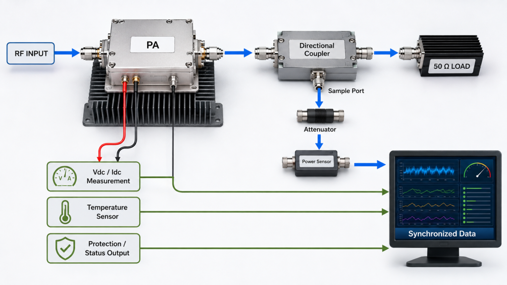
Useful records may include:
- actual Pin;
- corrected PA-port Pout;
- Vdc and Idc;
- efficiency metric and equation;
- RF and DC reference boundaries;
- waveform and duty cycle;
- agreed temperature measurement;
- cooling condition;
- load or VSWR condition;
- elapsed operating time;
- protection or alarm state;
- and S/N-linked unit identification.
The evidence should answer three different questions.
1. What was observed?
Examples include:
- Idc increased;
- temperature continued to rise;
- Pout drifted after stabilization;
- protection activated;
- one unit differed from another.
2. Under what condition?
The result is meaningful only when frequency, output reference plane, input drive, supply, load, duty cycle, cooling, and thermal state are known.
3. What does the observation actually prove?
Higher current confirms additional electrical burden.
Higher temperature confirms a thermal condition.
A protection event confirms that a monitored protection condition was triggered.
None of those observations alone proves the complete long-term failure mechanism.
This distinction is especially important when burn-in data is used.
RF Power Amplifier Batch Burn-In can help reveal early instability, drift, protection behavior, or unit-to-unit differences under a controlled stress condition.
A burn-in pass, however, is not proof of unlimited field lifetime.
Its evidence value is stronger when pre-test and post-test RF/DC measurements are tied to the same serial number and the same defined operating boundaries.
For supplier comparison, require equivalent test definitions before treating differences in efficiency, current, temperature, or protection events as meaningful reliability differences.
5. What Should the RFQ Require for Efficiency-Related Reliability Evidence?
A useful RFQ should not ask only:
“What is the PA efficiency?”
It should define the operating condition and evidence required to judge whether efficiency-related burden is consuming important margin.
RFQ Reliability Evidence
| Metric | Operating Boundary | Required Evidence | Acceptance Decision |
|---|---|---|---|
| PA efficiency | Defined DC and PA RF output boundaries | Pout, Vdc, Idc, metric equation | Electrical burden is understood |
| Hot-state performance | Required waveform, duty cycle, and cooling | Pout, Idc, temperature vs time | Required RF output and operating margins remain within agreed limits |
| Protection behavior | Defined electrical, thermal, and load limits | Alarm or protection log | No unexplained protection condition |
| Burn-in or endurance test | Agreed duration and operating condition | Pre/post S/N-linked measurements | No unacceptable drift or abnormal behavior |
For a practical RFQ, specify:
- required frequency points;
- corrected PA-port Pout;
- available Pin;
- efficiency metric and calculation boundary;
- Vdc and current limit;
- waveform and duty cycle;
- cooling method;
- ambient or cabinet condition;
- load or VSWR boundary;
- required operating duration;
- thermal stabilization criterion;
- protection thresholds and required alarm evidence;
- burn-in requirement where applicable;
- and S/N-linked test-report fields.
When comparing RF Power Amplifier Modules, request efficiency, hot-state current, temperature, and protection evidence under the same operating boundary rather than treating a headline efficiency percentage as a reliability guarantee.
The supplier does not need to predict every possible field failure mode.
But the supplied evidence should allow the integrator to determine whether the required RF operating point retains adequate electrical, thermal, and protection margin.
FAQ
Does low RF PA efficiency automatically mean poor reliability?
No.
Low efficiency can increase electrical and thermal burden, but reliability risk depends on whether those burdens materially reduce the operating margins required by the application.
A PA can still produce acceptable short-term RF output while operating closer to an electrical or thermal boundary.
Which measurements show that efficiency is reducing reliability margin?
Look for correlated changes in corrected Pout, Vdc, Idc, temperature, and protection state under the same defined RF, electrical, load, and thermal conditions.
Higher current or temperature can identify additional stress, but the root cause should be established before the result is attributed to efficiency.
Can burn-in prove long-term RF PA reliability?
Not by itself.
Burn-in can reveal early drift, instability, protection events, or abnormal unit behavior under a defined test condition.
It becomes stronger reliability evidence when the test conditions are documented and the pre-test and post-test measurements are linked to the individual module.
Conclusion
Low RF PA efficiency becomes a reliability concern when the resulting electrical or thermal burden materially reduces the specified operating margin under the required condition.
Short-term RF stability alone does not prove that adequate long-term reliability margin remains.
A lower efficiency percentage by itself is also not proof of poor reliability.
The decision should be based on correlated measurements of PA-port Pout, Vdc, Idc, temperature, load condition, duty cycle, cooling condition, and protection behavior at defined operating boundaries.
Higher current, temperature rise, hot-state drift, or protection events can reveal that margin is being reduced, but those observations should be separated from the confirmed root cause.
For an efficiency-related reliability review, send RF SKYPOWER the required frequency points, PA-port Pout, efficiency metric, Pin, Vdc and current limit, waveform and duty cycle, cooling condition, ambient range, load or VSWR boundary, required operating duration, protection criteria, burn-in requirement, and S/N-linked test evidence.
That evidence makes it possible to judge whether efficiency is merely a specification difference—or whether it is materially reducing the operating margin required by the application.