










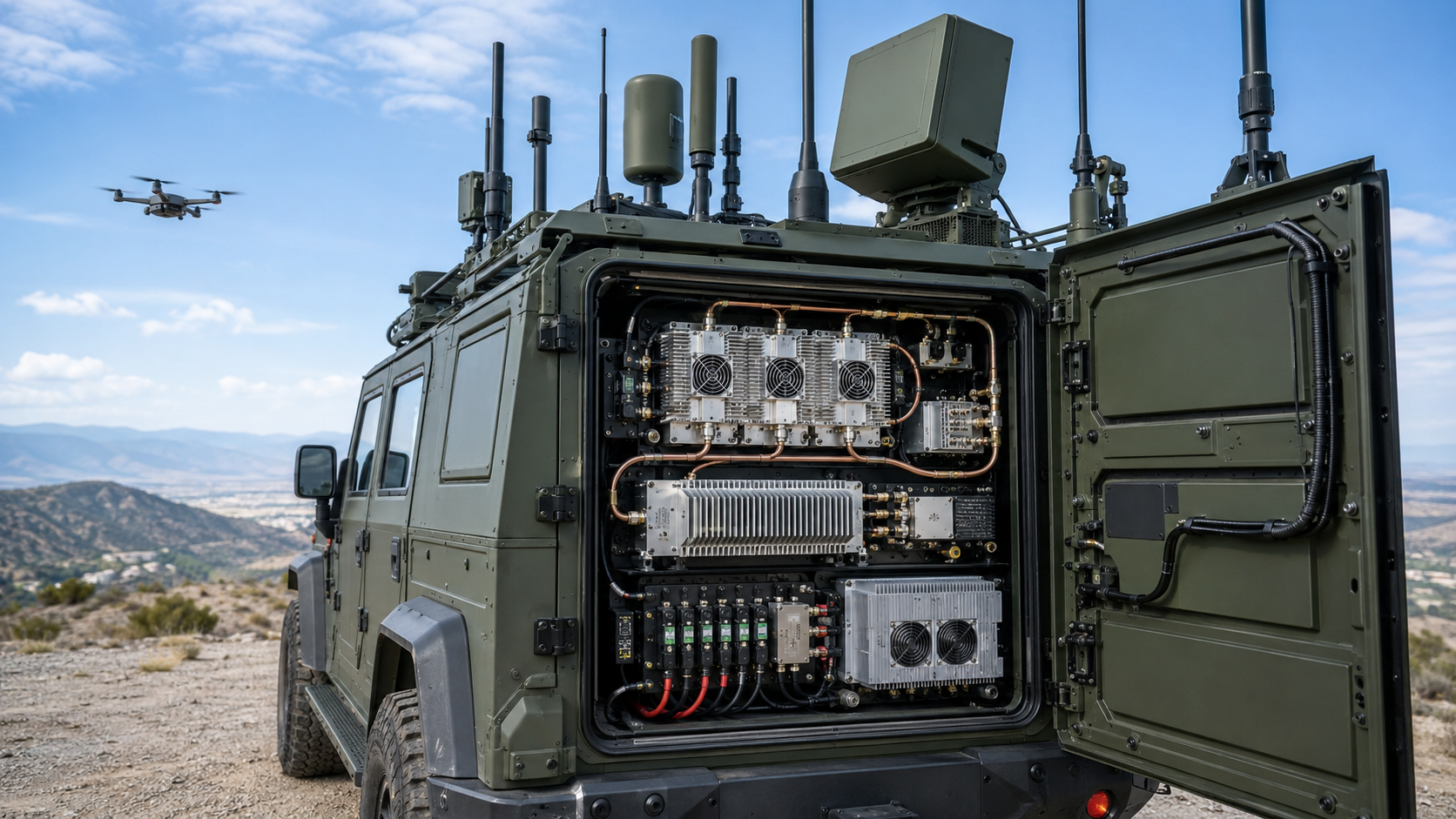
Vehicle RF PA efficiency can look acceptable on a regulated 28.0 V bench supply while the installed C-UAS platform still loses power margin during engine idle, battery-only operation, or simultaneous-channel load.
That does not automatically mean the PA itself is inefficient. The missing margin may be upstream—in the vehicle source, DC-DC converter, shared power path, or operating state.
Before approving the module, which PA measurements and vehicle states actually prove that the platform can support the required RF output?
1. Which Electrical Boundaries Must Be Separated in a Vehicle C-UAS Power Budget?
RF PA efficiency should be calculated at a defined PA electrical and RF boundary.
The vehicle-source and DC-DC boundaries do not redefine PA efficiency. They show how the PA load maps upstream into the vehicle power budget.
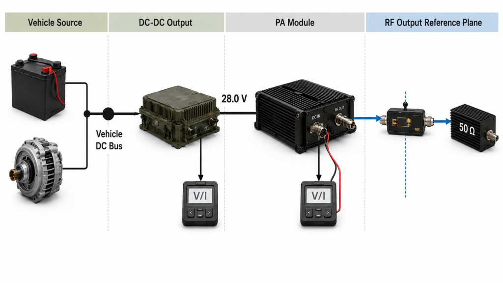
A useful review should separate:
- Vehicle-source boundary — battery, alternator, generator, or another defined DC source.
- DC-DC output boundary — the regulated supply feeding the PA cabinet or module.
- PA module boundary — voltage and current at the PA module terminals.
- PA RF output reference plane — the point where PA-level Pout is measured or corrected.
Measurements from one boundary should not be reported as though they represent another.
For example, a PA may use a regulated 28.0 V DC input even when the upstream vehicle source operates at a different voltage.
So:
PA-terminal current is not automatically battery, alternator, or generator current.
Vehicle Power Boundary Map
| Boundary | What to Measure | What It Proves | What It Does Not Prove |
|---|---|---|---|
| Vehicle source | Source voltage and current | Upstream electrical burden | Voltage and current actually reaching the PA |
| DC-DC output | Converter output voltage and current | Regulated bus loading | Upstream source current or source-path loss |
| PA module terminals | PA voltage and module current | PA electrical operating point | Complete vehicle load |
| PA RF output plane | Corrected PA-port Pout | RF output used for PA-level efficiency | Cabinet-, feeder-, or antenna-end output |
Define module efficiency at the PA boundary
For a PA module with one regulated DC input representing the complete stated module boundary:
Pdc,PA = VPA × IPA
For module DC-to-RF efficiency:
Module DC-to-RF Efficiency (%) = Pout,PA-port / Pdc,PA × 100%
If multiple DC rails or separately supplied auxiliary loads are included inside that PA boundary, sum the applicable DC input powers instead of assuming one V × I term represents the whole module.
For this module-level metric, Pout,PA-port should be measured or corrected at the defined PA module output reference plane.
A cabinet-output, feeder-end, or antenna-input value should not be substituted unless the efficiency metric is explicitly redefined for that wider system boundary.
Where several RF measurement planes are used, define the vehicle C-UAS RF power measurement points before comparing RF output with PA electrical demand.
Define Pout under mismatch
Under mismatch, the report should also state whether Pout means:
- forward RF power at the PA output plane;
- net RF power delivered after reflected power is accounted for;
- or another explicitly defined quantity.
Efficiency results based on different Pout definitions should not be compared directly.
The key question is therefore:
What efficiency metric was measured at the PA boundary, and how does that PA load map into the vehicle power system?
2. How Does PA Efficiency Become Vehicle Current and Runtime?
Once the PA boundary is clear, its electrical requirement can be mapped upstream.
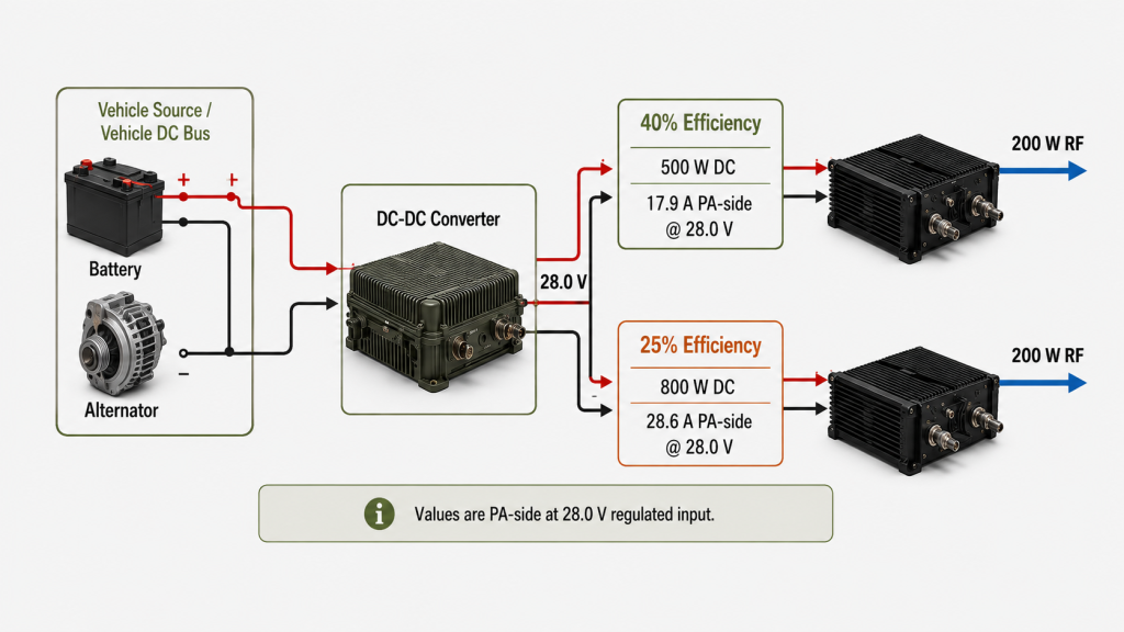
Consider an illustrative module DC-to-RF efficiency example—
Suppose:
Pout,PA-port = 200 W
At 40% module DC-to-RF efficiency:
Pdc,PA = 200 W / 0.40 = 500 W
At 28.0 V:
IPA = 500 W / 28.0 V ≈ 17.9 A
At 25% module DC-to-RF efficiency:
Pdc,PA = 200 W / 0.25 = 800 W
IPA = 800 W / 28.0 V ≈ 28.6 A
The RF output is identical, but the calculated PA-side DC current is not.
These values describe only the regulated 28.0 V PA-module boundary. They do not automatically include converter loss, fans, controllers, RF switches, computers, or other vehicle loads.
Map the PA load upstream
If a regulated converter output supplies several defined loads:
Pdc,out = Σ(Vj × Ij)
If converter efficiency at that operating point is ηconverter:
Pconverter,in = Pdc,out / ηconverter
Use converter efficiency applicable to the actual voltage, load, and thermal condition—not an unrelated peak-efficiency figure.
For a calculated vehicle-source budget:
Pvehicle,total = Pconverter,in + Ppath,loss + Pother,source
Here:
Ppath,lossrepresents source-side wiring or distribution loss not already included elsewhere.Pother,sourceincludes only source-side loads not already counted inPdc,out.
Loads must not be counted twice.
If source voltage and current are measured directly at the defined vehicle-source boundary, that measured source power already includes downstream path losses, so those losses should not be added again.
Then:
Ivehicle,source = Pvehicle,total / Vvehicle,source
This is why a 17.9 A or 28.6 A PA-terminal current should not be copied directly into a battery or alternator calculation.
If the DC path itself becomes the problem, review RF PA efficiency and DC power-supply stress separately.
Estimate battery-only runtime
A basic screening relationship is:
Estimated Runtime ≈ Usable Battery Energy / Average Vehicle Load
When usable energy is expressed in Wh and average source-side power in W, the result is an approximate runtime in hours.
The estimate may still depend on:
- battery condition and temperature;
- discharge limits and required reserve;
- converter efficiency;
- RF duty cycle;
- active channel count;
- cooling and controller loads;
- and other vehicle equipment.
So the result is a power-budget estimate, not guaranteed operating endurance.
3. Which Vehicle States and Simultaneous Loads Must Be Tested?
A regulated bench supply can verify PA behavior under controlled conditions.
It cannot prove that the installed vehicle will reproduce the same electrical and thermal margin.
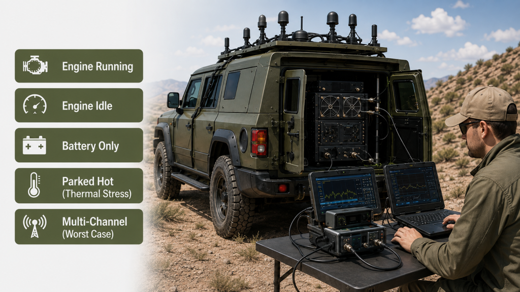
Vehicle acceptance should therefore cover the operating states that matter to the real platform, typically including:
- engine running;
- engine idle;
- battery-only operation;
- parked hot condition;
- worst simultaneous-channel operation.
The exact matrix should follow the vehicle architecture and deployment requirement.
Vehicle-State Acceptance Matrix
| Vehicle State | Required Measurements | Main Acceptance Risk |
|---|---|---|
| Engine running | Source V/I, converter V/I, PA-terminal V/I, PA-port Pout, temperature | Assumed charging margin not reproduced |
| Engine idle | Source V/I, converter output, PA-terminal V/I, Pout | Reduced source margin |
| Battery-only | Source V/I, PA-terminal V/I, Pout, elapsed time | Runtime or low-voltage margin |
| Parked hot | Pout, Vdc, Idc, temperatures, protection state | Thermal derating or protection |
| Worst simultaneous-channel state | Source V/I, bus data, branch data where needed, Pout by channel | Combined electrical and thermal load |
Engine idle matters when the system must transmit while stationary. Battery-only operation matters when the charging source is unavailable. Parked-hot testing matters because real cabinet temperature and airflow may differ substantially from an open bench.
For thermal budgeting, PA dissipation, converter loss, and other cabinet loads should remain separate heat sources before they are combined. Use RF PA heat-load calculations for the full thermal boundary.
Multi-channel systems also require simultaneous-load testing. If several PAs share the same regulated path, the shared DC bus in a vehicle PA cabinet should be checked separately for branch loading and voltage-drop interactions.
The purpose is simple:
Test the states that can remove the electrical or thermal margin needed to maintain the required RF output.
4. What Can Bench Data Prove About Vehicle Readiness?
A controlled 28.0 V PA test can establish useful module-level evidence, including:
- frequency;
- actual Pin;
- corrected PA-port Pout;
- PA-terminal Vdc and Idc;
- efficiency metric at the stated boundary;
- waveform and duty cycle;
- load condition;
- thermal state;
- protection status.
What it does not automatically prove is that the installed vehicle can reproduce the same PA operating condition.
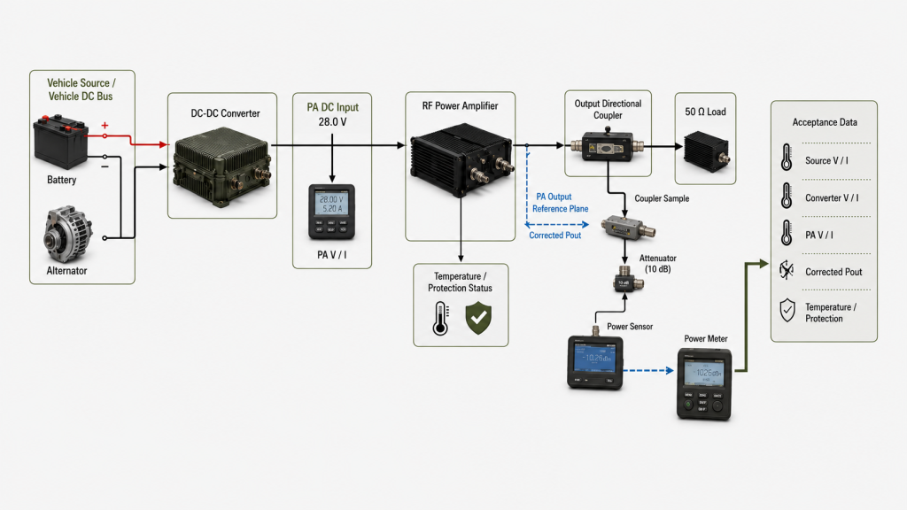
Vehicle approval needs a traceable evidence chain:
vehicle state → source measurement → converter measurement → PA-terminal measurement → corrected PA-port Pout → thermal/protection state
That chain should answer:
- What Vdc and Idc does the PA require?
- What corrected PA-port Pout does it produce?
- What converter input power is required?
- What source-side current does the vehicle experience?
- Which concurrent loads are active?
- Which vehicle state creates the smallest margin?
- Is any protection or derating active?
Mechanical conditions such as vibration, mounting, connector movement, or cable routing can matter, but they should not be labelled an “efficiency problem” unless the measured electrical or RF evidence supports that conclusion.
5. What Evidence Should a Vehicle C-UAS RFQ Require?
“28 V RF PA for vehicle use” is not a complete engineering requirement.
For a vehicle C-UAS project, define:
- Vehicle-source voltage range
- Regulated PA input condition
- DC-DC converter rating and applicable efficiency
- Required frequency points
- Required PA-port Pout
- Pout definition under mismatch
- Available Pin at the PA input reference plane
- Efficiency metric: metric name, equation, RF power terms, and exact DC measurement boundary
- Active channel combinations
- Waveform and duty cycle
- Engine-running and engine-idle states
- Battery-only duration where required
- Thermal and cooling condition
- Load or VSWR boundary
- Protection evidence
- Required test-report fields and traceability
When comparing RF Power Amplifier Modules, define both the PA-level efficiency boundary and the upstream vehicle-source boundary before using efficiency or current data for platform approval.
The supplier does not need to recreate the complete vehicle.
But the PA data must be detailed enough for the integrator to map the module into the actual converter, source, runtime, thermal, and simultaneous-load budget.
For the broader module-level decision, use the C-UAS RF PA selection workflow to compare frequency, power, thermal, control, and acceptance requirements beyond the vehicle power budget.
FAQ
Does a 28 V bench test prove vehicle readiness?
No.
A regulated 28.0 V bench test can prove PA behavior at the defined module boundary, but not the complete battery, alternator, converter, shared-bus, runtime, or vehicle thermal condition.
Is PA-terminal current the same as battery or alternator current?
Not necessarily.
PA-terminal current belongs to the regulated PA input boundary. Upstream source current depends on source voltage, converter efficiency, path loss, other loads, and vehicle state.
Which vehicle state should be used for RF PA acceptance?
Use the states that represent the intended operating envelope.
The critical state is the one that leaves the smallest relevant electrical, runtime, thermal, or protection margin while the required RF performance is maintained.
Conclusion
A regulated 28.0 V bench result does not by itself prove that a vehicle C-UAS platform can support the RF PA in real operation.
For the module DC-to-RF metric used in this article, efficiency should be calculated from corrected PA-port Pout and the complete DC power entering the defined PA module boundary. If PAE, drain efficiency, or another metric is used, retain that metric’s own RF terms and DC denominator rather than substituting the module-efficiency formula.
That PA electrical requirement should then be mapped upstream through the DC-DC stage and vehicle-source boundary to determine the actual platform power budget.
PA-terminal current therefore tells you what the amplifier requires at its own DC boundary. It does not automatically tell you the current demanded from the battery, alternator, generator, or another upstream source.
Vehicle approval should then reproduce or validate the operating states that matter: engine running, engine idle, battery-only operation, parked-hot conditions, and worst simultaneous-channel loading where applicable.
For a vehicle C-UAS power-budget review, send RF SKYPOWER the vehicle-source voltage range, regulated PA input condition, DC-DC converter rating and applicable efficiency data, required frequency points, PA-port Pout and its measurement definition, available Pin, active-channel combinations, waveform and duty cycle, battery-only duration where required, vehicle operating states, cooling condition, load or VSWR boundary, protection requirements, and test-report format.
Those boundaries show whether the vehicle can actually support the PA operating condition required by the project—not merely whether the PA passes on a controlled 28.0 V bench supply.