











A 28V RF PA can reach the required output on a bench and still expose an RF PA power supply problem when the complete cabinet is loaded. The supply display may continue to look normal while module-terminal voltage falls, available supply-current margin shrinks, or several channels begin competing for the same DC power path.
Low RF PA efficiency can make this problem harder because some operating points require more DC power for the same RF output. But high current does not automatically prove poor efficiency, and a protection alarm does not automatically prove a bad PA.
The real engineering question is: how do you separate efficiency-related current demand from an undersized supply, DC-path loss, shared-load stress, or another power-chain problem before approving the module?
1.When Does Low RF PA Efficiency Increase DC Current Demand?
The first step is to define what “efficiency” means.
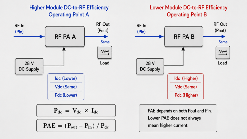
For a defined drain-efficiency or module DC-to-RF efficiency boundary, lower efficiency at the same RF output means that more DC input power is required at that electrical boundary.
Under a steady DC operating condition, input power at a defined electrical boundary can be calculated from the voltage and current measured at that same boundary:
Pdc = Vdc × Idc
If Vdc remains approximately constant, higher DC power demand appears as higher current.
For pulsed or dynamically varying operation, the voltage and current measurement method and averaging window should be defined so that DC power represents the same operating interval rather than unrelated average readings. If the waveform varies significantly with the operating cycle, synchronized voltage and current data provide a more meaningful power boundary than multiplying separately averaged values.
The measurement location also matters. If Vdc and Idc are measured at the PA module terminals, the result represents module DC input power. It should not be treated as final-stage drain power unless the efficiency metric is explicitly defined at that drain-supply boundary.
PAE requires separate interpretation because RF input power is part of the calculation:
PAE = (Pout − Pin) / Pdc
Pin and Pout must be expressed in linear power units, such as watts, before they are used in the PAE equation. Both values should also be referred to the defined PA input and output measurement planes, with applicable RF-path corrections accounted for.
At the same Pout, lower PAE can result from:
- Higher RF input drive
- Higher DC input power
- Both higher RF drive and higher DC input power
A lower PAE percentage therefore does not, by itself, prove that DC current must have increased.
Before current demand is compared, the PAE vs drain efficiency measurement boundary should be defined so the RF and DC power terms remain consistent at every operating point.
For practical power-supply review, engineers should examine at least:
- Frequency
- Actual Pin at the defined PA input plane
- Actual Pout at the defined PA output plane
- Applicable RF-path corrections
- Efficiency metric
- RF and DC measurement boundaries
- Module-terminal Vdc
- Idc
- Load condition
- Duty cycle and measurement window
- Thermal state
Only then can a high-current operating point be linked confidently to conversion efficiency rather than to a different RF output target, drive condition, load, supply condition, or measurement boundary.
2.Why Can Higher PA Current Expose a Weak DC Power Path?
Higher PA current does not create cable or connector resistance. It makes the resistance already present in the DC path more costly.
The basic voltage-drop relationship is:
ΔV = I × Rpath
The same path resistance produces a larger voltage drop as current increases.
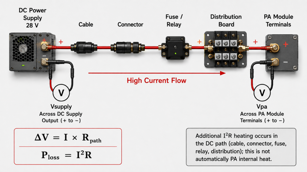
This is why a supply can still display 28V while the PA itself receives less voltage under load. The difference may exist across cables, connectors, fuses, relays, distribution hardware, PCB traces, return paths, or other elements between the supply output and the PA terminals.
The correct comparison is therefore not only:
What voltage does the power supply display?
It is also:
What voltage reaches the PA module terminals at the actual RF operating point?
A system designed around a 28V nominal supply should define the loaded RF PA voltage margin at the module terminals under real RF load, not only from the nominal supply value.
Higher current also increases resistive loss in the DC path:
Ploss = I²R
This is power-chain heating, not automatically PA internal heat.
A connector, cable, fuse, relay, or distribution point can become warmer as current rises even when the PA’s internal thermal design has not changed. The distinction matters because a hot DC path and a hot RF PA may require completely different corrective actions.
When module-terminal voltage begins to fall, the next step should not be to blame low efficiency immediately. Engineers should compare supply-output voltage, PA-terminal voltage, current, RF output, and the active operating condition under the same timestamp or defined test interval.
3.Why Does Single-Module Testing Miss Multi-Channel Power Stress?
A single PA can pass on a bench while the complete cabinet still lacks enough DC margin.
Several modules operating simultaneously can push total DC demand beyond the available supply or distribution margin, even when every individual PA passed by itself.
For a multi-channel system, engineers should distinguish:
- Current demand of each PA at its actual operating point
- Total current when the required channel combination is active
- Current available from the supply under sustained load
- Voltage at the distribution point
- Voltage at each PA module
- Shared return-path or distribution effects
- Frequency and Pout of each active channel
- Duty cycle and simultaneous operating time
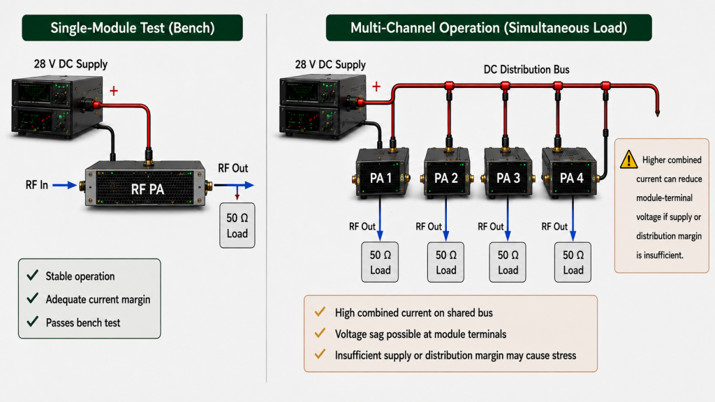
Simultaneous-load validation should use the actual operating combination rather than only the sum of individual nameplate values. Different channels may operate at different frequencies, Pout levels, drive conditions, or duty cycles, so their real DC demand may not match a simple nominal estimate.
For example, four modules should not be approved only because each module behaves normally when tested separately. The cabinet test must confirm that the required combination can operate together without unacceptable module-terminal voltage drop, current limiting, controller reset, thermal escalation, or protection action.
This is particularly important when several channels share one power supply or DC bus. Shared-load behavior has its own engineering boundary and should not be inferred from a single-channel result.
In fixed-site systems with long duty cycles, several simultaneous PA channels, and limited maintenance access, discovering insufficient DC margin after installation can be expensive. That makes full-load evidence more valuable before RFQ and acceptance.
4.What Symptoms Can DC Power Stress Create?
DC power stress does not produce one universal symptom.
Depending on the supply, DC path, PA control behavior, load condition, thermal state, and protection logic, engineers may observe:
- Module-terminal voltage sag
- Current limiting
- Reduced or unstable RF output
- Controller or communication reset
- Temperature rise
- Undervoltage alarm
- Overcurrent alarm
- Protection foldback
- Temporary shutdown
- Recovery after load removal
These are observations, not root-cause labels.
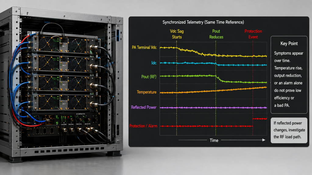
An output reduction does not prove low efficiency. A temperature alarm does not prove insufficient cooling. A protection event does not prove a defective PA.
The event sequence matters.
If voltage falls before RF output falls, the DC path deserves attention. If DC input power rises while Pout and the other operating conditions remain comparable, efficiency may be part of the explanation. If reflected power changes at the same time, the RF load path also needs review.
When reduced or unstable RF output becomes the main symptom, RF PA output drops from DC power issues should be diagnosed by comparing supply voltage, module-terminal voltage, current, and event timing before efficiency is blamed.
The goal of this page is narrower: identify whether efficiency-related DC demand is consuming power margin, or whether the apparent efficiency problem is actually coming from the supply and distribution system.
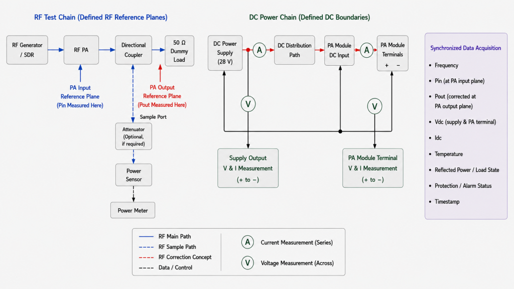
5.What Evidence Separates Low Efficiency from Weak DC Power Design?
A useful test should let engineers distinguish PA conversion behavior from losses elsewhere in the power chain.
| Observation | What it may indicate | Evidence to check |
|---|---|---|
| High current at comparable Pout | Lower DC-to-RF efficiency, reduced module-terminal voltage, or another operating-point difference | Frequency, Pin, Pout, efficiency metric, module-terminal Vdc, Idc, load and thermal state |
| Supply voltage normal but PA voltage low | DC-path voltage loss | Measure supply output and PA-terminal voltage under the same load |
| One module passes but several fail together | Combined-load or shared-distribution margin | Per-channel current, total current, bus voltage, module-terminal voltage |
| Output falls after operating time | Supply, thermal, load, or protection interaction | Pout, Vdc, Idc, temperature, load state, alarm timeline |
| Problem appears at one frequency | Frequency-specific operating demand or RF-path effect | Compare the same RF, DC, load, and thermal boundaries by frequency |
| Alarm appears during high load | Protection threshold reached or another boundary exceeded | Voltage, current, temperature, forward/reflected power, protection log |
The measurement sequence should remain consistent.
If Pout is comparable but module-terminal voltage is falling while current changes, calculate the DC power at the defined PA boundary before attributing the symptom to efficiency. Then compare that result with the supply-end voltage and current to separate PA conversion behavior from loss or limitation in the DC distribution path.
Likewise, if a high-current condition appears at one frequency, do not compare it with another frequency unless Pout, RF drive rule, efficiency metric, RF and DC boundaries, load condition, and thermal state are also comparable.
Test evidence is more useful when it records the actual operating timeline instead of isolated screenshots.
A practical evidence set can include:
- Frequency
- Pin and Pout at defined RF reference planes
- Applicable RF-path corrections
- Efficiency metric and formula
- Module-terminal Vdc and Idc
- Supply-output voltage and current
- Simultaneous active channels
- Duty cycle and test duration
- DC measurement or averaging window for dynamic operation
- Cooling condition
- Forward and reflected power when relevant
- Protection or alarm status
- Recovery behavior
- S/N-linked report when unit-level acceptance is required
This evidence does not merely show that a symptom occurred. It helps identify where the electrical margin disappeared.
6.What Should the RFQ Define for DC Power Margin?
“28V input” is not enough information to approve the DC power chain.
An RFQ should separate what the buyer can define from what the PA supplier should confirm under the agreed operating conditions.
| RFQ item | Buyer should define | Supplier should confirm |
|---|---|---|
| Target frequencies | Actual required operating points or range | Test coverage at the required frequencies |
| Required Pout | Target or minimum RF output at each critical point | Measured Pout at the defined RF reference plane |
| Efficiency metric and boundary | Required metric or acceptance method if project-defined | Metric used, formula, RF planes, and DC measurement boundary |
| DC supply boundary | Available voltage range and supply architecture | Required module-terminal voltage under the stated RF condition |
| DC current | Available continuous and peak current budget | Measured Idc at the defined frequency, Pout, drive, duty cycle, and thermal state |
| Simultaneous operation | Number and combination of channels expected to operate together | Per-channel and total current evidence for the required combination |
| Operating condition | Required duty cycle, duration, cooling, and ambient boundary | Vdc, Idc, Pout, temperature, and protection behavior under that condition |
| DC path constraints | Known cable length, distribution architecture, connectors, relays, or cabinet limitations | Any module-side voltage/current requirement that affects the path design |
| Protection and evidence | Required alarms, foldback, shutdown, recovery, and acceptance documentation | Measured protection behavior and agreed test-report content |
This distinction matters because the buyer may know the cabinet’s available DC budget but not the PA’s actual current requirement before testing. The supplier should therefore return measured Vdc and Idc under the project-defined RF, duty-cycle, thermal, and load conditions rather than asking the buyer to guess the module’s full-load current.
Once the required RF output and real DC current demand are defined, module selection should review the PA together with the project’s supply voltage, current budget, duty cycle, cooling boundary, DC path, and protection requirements.
RF SKYPOWER’s Custom RF Power Amplifier Modules provide an engineering starting point for projects where RF output, DC integration, control, protection, and operating conditions need to be reviewed together before RFQ.
The correct power supply should not be selected from rated PA output alone. The engineering review should compare the project’s available electrical margin with the PA’s measured demand at the actual operating points.
FAQ
Does low RF PA efficiency always mean higher current?
No.
For drain efficiency or a defined module DC-to-RF efficiency, lower efficiency at the same Pout and the same DC boundary means higher DC input power demand. If DC voltage remains comparable, that generally appears as higher current.
PAE requires separate interpretation because Pin is part of the calculation. A lower PAE value can result from higher RF input drive, higher DC input power, or both.
Why can the PA receive less than 28V when the power supply still shows 28V?
Because voltage can be lost between the power supply and the PA module under load.
Cable, connector, fuse, relay, distribution, return-path, and other resistance can create a larger voltage drop as current increases. The relevant acceptance value is therefore the voltage measured at the defined PA input boundary under the required operating load, not only the unloaded or supply-terminal reading.
What evidence should be requested before approving the DC power chain?
The buyer should define the target frequencies, required Pout, available DC voltage and current budget, simultaneous-channel requirement, duty cycle, cooling condition, DC-path constraints, and acceptance requirements.
The supplier should then confirm the efficiency metric and measurement boundaries, measured module-terminal Vdc and Idc, Pout, applicable RF-path corrections, thermal and protection behavior, and the required test evidence under those operating conditions.
The goal is to distinguish PA conversion behavior from supply and DC-distribution loss before the system is approved.
Conclusion
Low RF PA efficiency can increase DC power supply stress, but only when the efficiency definition, RF reference planes, DC measurement boundary, and operating condition support that conclusion.
For drain efficiency or module DC-to-RF efficiency, lower efficiency at the same Pout means more DC input power is required; at a comparable DC voltage, that means more current. PAE must be interpreted separately because RF input power is part of the calculation, and Pin and Pout must be evaluated as linear RF power at defined measurement planes.
The system-level risk appears when the PA’s real DC demand consumes the margin available in the supply or distribution path. Module-terminal voltage may fall, resistive losses may rise, simultaneous channels may exceed the available capacity, and protection or output symptoms may appear. None of those symptoms should be assigned to low efficiency until the RF operating point, DC power, supply-end and module-end voltage, load, thermal state, and event timing have been compared.
Before RFQ, send RF SKYPOWER your target frequencies, required Pout, efficiency metric, available DC voltage and current budget, simultaneous-channel requirement, duty cycle, cooling condition, DC-path constraints, protection requirements, and required test evidence. The engineering review can then compare those project limits with the PA’s measured module-terminal voltage and current under the defined operating conditions.