










A PA can reach the required Pout, show acceptable RF PA CW efficiency, and trigger no alarm during the first few minutes of a bench test. That result may still describe only the cold or transitional operating state—not the condition the module will hold during continuous CW operation.
As the PA, heatsink, DC path, and surrounding air warm up, Pout, Pin, Vdc, Idc, temperature, and protection behavior may move together. An efficiency value recorded before that transition is complete may therefore be technically correct for that moment but still be weak evidence for CW approval.
The real question is: when during a continuous CW run does the efficiency result become representative enough to support module acceptance?
1. Why Can a Short Efficiency Test Miss the Real CW Condition?
A short test can confirm that the PA powers up, reaches output, and operates normally at the beginning of the run. It does not automatically prove that the same electrical condition will remain after the module and surrounding thermal system have warmed.
During true CW operation, RF remains continuously on for the defined test interval; there is no planned RF-off recovery period. The PA must sustain the required RF output while its electrical and thermal state develops under continuous load.
That makes test duration important—but duration alone is not the acceptance criterion.
A result recorded after 30 seconds, 5 minutes, or another arbitrary time can still represent a transition state if key variables are continuing to move.
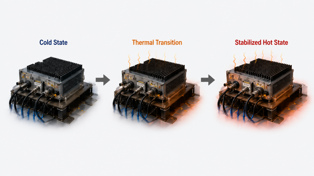
For CW efficiency evaluation, engineers should distinguish three practical states:
- Cold state: the PA has only recently started operating.
- Thermal transition: electrical and temperature-related values are still trending.
- Stabilized hot-state observation window: the monitored acceptance variables satisfy the project-defined stabilization criteria during the agreed observation period.
The exact time required to reach that final condition cannot be assumed from one universal number. It depends on the PA, output level, cooling arrangement, enclosure, ambient condition, RF load, and test setup.
This is why a short efficiency screenshot cannot substitute for CW evidence.
The detailed distinction between burst, intermittent, high-duty, and true continuous operation belongs in the project’s duty-cycle definition. Where that boundary itself is the main question, RF PA duty-cycle failures should be evaluated separately.
For this page, the relevant requirement is simple:
If the project requires continuous CW output, the efficiency result should represent the defined continuous operating condition—not only the first minutes after RF is enabled.
2. When Should RF PA Efficiency Be Measured During CW Operation?
CW efficiency should not be accepted merely because a preset number of minutes has elapsed.
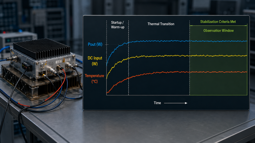
A more useful approach is to define a stabilized hot-state observation window.
A practical stabilized observation window is reached when the monitored variables used for acceptance satisfy the agreed trend or drift limits during the defined observation period while the test conditions remain unchanged.
Those test conditions should include:
- Frequency
- RF drive rule
- Required Pout
- Efficiency metric
- RF measurement planes
- DC measurement boundary
- Load condition
- Cooling configuration
- Ambient condition
- Continuous operating state
The monitored variables should normally include at least:
- Pin
- Pout
- Voltage and current at the DC boundary used by the selected efficiency metric
- Module-terminal Vdc and Idc when required for system-level acceptance
- Selected temperature point
- Protection status
What counts as a material trend should be defined before the test.
The RFQ or acceptance plan should state:
- Which variables are used to judge stabilization
- The observation-window duration
- The allowable drift or trend criterion for those variables
- Any averaging or sampling method used
- The operating conditions that must remain unchanged throughout that window
There is no single universal stabilization threshold that applies to every PA, cooling system, enclosure, frequency, output level, and ambient condition.
The purpose is not to prove that the entire physical system has reached perfect thermal equilibrium. Temperatures can continue changing slowly or respond to airflow and ambient variation even after the electrical behavior has become sufficiently repeatable for the agreed acceptance test.
The purpose is to establish a predefined, repeatable hot-state window that represents the operating condition the PA is expected to sustain.
If Pout is still moving beyond the agreed drift limit, DC input power is still trending materially, or the monitored temperature has not met the specified stabilization criterion, the PA is still in a transition that may affect the reported efficiency.
A cold-state efficiency value can still be valid data. It simply should not be labeled as the stabilized CW result.
Likewise, a single high temperature reading does not prove stabilization. Temperature should be identified by measurement location and interpreted together with RF output, DC input, and time trend. It should not be treated as junction temperature unless junction temperature is actually measured or validly derived by an agreed method.
CW operation requires dissipation associated with the selected operating point to be rejected continuously. Detailed conversion from electrical efficiency to thermal load depends on the selected efficiency metric and electrical boundary and is covered separately in RF PA heat load.
The CW test should therefore answer:
Has the PA entered the predefined hot-state observation window, and does the required efficiency remain acceptable throughout that window?
3. Which Values Must Be Tracked Together During the CW Run?
An efficiency percentage is only useful when the RF and DC values behind it belong to the same operating condition.
At minimum, the test should record:
- Frequency
- Actual Pin
- Actual Pout
- Efficiency metric and formula
- RF input and output reference planes
- Applicable RF-path corrections
- DC measurement boundary required by the selected efficiency metric
- Voltage and current at that DC boundary
- Module-terminal Vdc and Idc when system-level supply evidence is also required
- Elapsed operating time
- Selected temperature point
- Cooling condition
- Load or VSWR condition
- Protection status
These values should describe the same operating interval.
This matters because the system can change during CW warm-up.
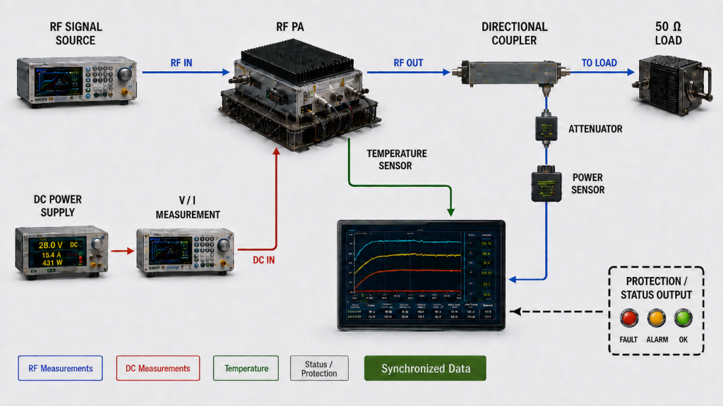
If Pout is taken from one moment, DC current from another, and temperature from a third, the calculated efficiency may combine operating states that never actually existed at the same time.
The RF-drive rule should also be defined.
Two common test modes can be valid:
Constant measured Pin
The same measured RF input power is maintained while engineers observe how Pout, gain, DC power, efficiency, temperature, and protection behavior change during the CW run.
Adjusted Pin to maintain a target Pout
RF drive is adjusted as needed so that the PA continues producing the agreed output, while engineers observe the required Pin, DC demand, efficiency, temperature, and protection margin.
These methods answer different questions.
A constant-Pin test helps show how PA behavior changes under the same measured RF input drive.
A target-Pout test helps show what RF drive and DC demand are required to sustain the project’s specified output.
Neither method should be mixed with the other without being identified in the report.
The DC boundary also matters.
Under a steady operating condition, electrical input power at a defined DC boundary can be calculated from the voltage and current measured at that same boundary:
Pdc = Vdc × Idc
If Vdc and Idc are measured at the PA module terminals, the result represents module DC input power.
It should not automatically be treated as transistor or final-stage drain power. If drain efficiency is the selected metric, the voltage and current used for Pdc must correspond to the defined drain-supply boundary.
For pulsed or dynamically varying electrical conditions, the voltage/current sampling, synchronization, and averaging method should be defined so that the reported Pdc represents the same operating interval.
RF input and output measurements require the same discipline.
Pin and Pout should be referred to the defined PA input and output planes, with applicable cable, attenuator, coupler, connector, adapter, or fixture corrections included.
Without consistent RF reference planes, metric-specific DC boundaries, and synchronized measurements, a changing efficiency number may describe the test method as much as the PA.
4. What Can a Hot-State Efficiency Change Actually Prove?
A change in efficiency during a CW run is an observation.
It is not, by itself, a root-cause diagnosis.
If efficiency becomes lower after warm-up, possible contributors can include changes in:
- RF input drive
- RF output
- DC input power
- Device operating condition
- Bias behavior
- Matching
- Load condition
- Module-terminal voltage
- Temperature
- Protection state
The first job is therefore to determine what changed during the same operating interval.
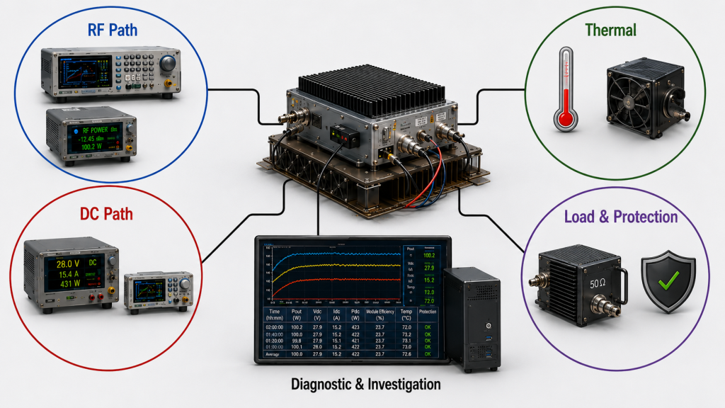
If Pout falls while Pin, DC input power, load condition, measurement boundaries, and protection state remain comparable, the hot-state RF behavior deserves attention.
If module-terminal voltage falls at the same time, the DC supply or distribution path may also be contributing.
If Idc changes while Pout remains comparable, review the synchronized Vdc and Idc at the defined DC boundary before concluding that DC input power has increased.
The relevant electrical relationship is:
Pdc = Vdc × Idc
Only after the synchronized Pdc is established should engineers compare the efficiency metric, RF drive condition, Pout, temperature, and other measurement boundaries.
Current alone is evidence. It is not the same thing as DC input power.
If reflected power changes during the same interval, the RF load or matching condition also requires review.
If protection activates, the efficiency value may no longer represent unrestricted normal operation and should be identified accordingly in the report.
The correct interpretation is therefore:
CW efficiency change → review synchronized RF, DC, thermal, load, and protection evidence → identify which boundary changed → assign cause only after comparison
Not:
CW efficiency changed → thermal problem
and not:
CW efficiency changed → bad PA
Hot-state gain can also change during CW operation, but gain drift is a separate acceptance question. Where the main issue is RF gain behavior rather than efficiency, RF PA hot-state gain should be reviewed separately.
Likewise, module-terminal Vdc and Idc can reveal whether the system-level DC condition remained acceptable, but detailed diagnosis of supply or distribution problems belongs in the separate DC power review.
The purpose of the CW efficiency test is not to force every abnormal symptom into one efficiency explanation.
It is to determine whether the PA continues operating within the required RF, DC, thermal, load, and protection boundaries during the predefined hot-state observation window.
5. What Evidence Is Enough for CW Acceptance?
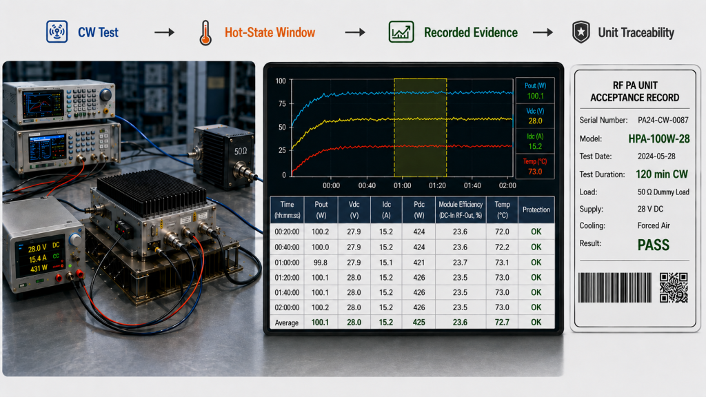
A CW acceptance report should make it possible to reconstruct the operating condition under which the efficiency result was obtained.
| Evidence | Why it matters | Minimum boundary to record |
|---|---|---|
| Pin and Pout | Defines the RF operating point | Defined RF input/output planes and applicable corrections |
| DC voltage and current | Defines the DC operating point used by the selected efficiency metric | Measure at the required metric-specific DC boundary; separately record module-terminal Vdc and Idc when system-level evidence is required |
| Efficiency metric | Prevents PAE, drain, and module-efficiency confusion | Formula plus exact RF and DC measurement boundaries |
| Time / stabilization | Separates cold, transition, and accepted hot-state data | CW start time, observation-window duration, monitored variables, and agreed drift criterion |
| Temperature | Indicates thermal operating state | Measurement location, trend, and agreed stabilization criterion |
| Cooling | Makes the test condition repeatable | Heatsink, airflow, liquid cooling, or cabinet configuration |
| Load condition | Separates PA behavior from RF-load effects | Dummy load, VSWR, or another defined load boundary |
| Protection status | Shows whether the result represents normal unrestricted operation | Alarm, foldback, derating, shutdown, and recovery status |
The report should not contain only one final efficiency percentage.
A more useful CW record shows how the main variables move from startup into the accepted hot-state observation window.
That can include:
- Initial Pin and Pout
- Initial DC voltage and current at the selected efficiency boundary
- Initial module-terminal Vdc and Idc when required
- Hot-state Pin and Pout
- Hot-state DC voltage and current at the selected efficiency boundary
- Hot-state module-terminal Vdc and Idc when required
- Selected temperature trend
- Stabilization observation window
- Agreed allowable drift criteria
- Efficiency metric and calculated result
- Protection status
- Total CW duration
- Load condition
- Cooling configuration
- RF and DC measurement boundaries
If the project uses PAE:
PAE (%) = ((Pout − Pin) / Pdc) × 100%
Pin and Pout must first be expressed in linear power units such as watts before being used in the calculation.
They must also refer to the defined RF input and output measurement planes.
The Pdc term must represent the DC input power at the electrical boundary defined for that PAE measurement.
If the project uses drain efficiency, the DC voltage and current must correspond to the defined drain-supply boundary.
If it uses a module DC-to-RF efficiency metric, module-input DC power may be the appropriate boundary.
These quantities should not be interchanged merely because they are all reported as “efficiency.” Before CW efficiency results are compared, the PAE vs drain efficiency measurement boundary should be defined so each percentage uses the correct RF and DC power terms.
The acceptance result should therefore say more than:
Efficiency = 38%
A useful acceptance statement is closer to:
At the specified frequency, RF drive rule, Pout target, RF reference planes, selected efficiency metric, metric-specific DC boundary, cooling configuration, load condition, and predefined CW observation window, the measured efficiency remained within the agreed acceptance requirement without unacceptable RF drift or protection action.
The actual numerical acceptance limit, allowable drift, duration, and stabilization criteria should come from the project requirement rather than from a generic universal threshold.
For unit-level acceptance, the report can also link the result to the actual module serial number when the project requires traceable delivered-unit evidence.
6. What Should the RFQ Define for CW Efficiency Testing?
A vague RFQ such as:
Need a high-efficiency PA for continuous operation.
does not define enough information for a supplier to produce comparable CW evidence.
The buyer should define the operating and acceptance boundaries, while the supplier should confirm the measured PA result under those conditions.
| RFQ item | Buyer should define | Supplier should confirm |
|---|---|---|
| Target frequency | Required operating point or range | CW test coverage at the required frequency |
| Sustained Pout | Required continuous RF output | Measured Pout at the defined output plane |
| RF drive rule | Constant measured Pin or adjusted Pin to target Pout | Actual Pin and drive behavior during the CW run |
| Efficiency metric | PAE, drain efficiency, module efficiency, or another agreed metric | Formula plus exact RF and DC measurement boundaries |
| CW duration and stabilization | Required CW duration, observation-window duration, monitored variables, allowable drift criterion, and averaging method if applicable | Actual CW duration, stabilization evidence, and data throughout the agreed observation window |
| DC measurement | Required module-input supply condition and any metric-specific DC requirement | Voltage and current at the DC boundary required by the selected efficiency metric, plus module-terminal Vdc and Idc when requested |
| Cooling condition | Required heatsink, airflow, liquid cooling, or cabinet condition | Cooling configuration used during testing |
| Ambient condition | Project-relevant temperature boundary | Ambient condition recorded for the result |
| Load / VSWR | Required RF load condition | Test load, VSWR, and reflected-power condition where applicable |
| Protection criteria | Acceptable alarm, foldback, derating, shutdown, and recovery behavior | Recorded protection status throughout the CW run |
| Acceptance evidence | Required report, traceability, plots, synchronized data, or other measurements | Actual test evidence delivered for review |
This separation matters.
The customer should not have to guess how much current the PA will draw, how long stabilization will take, or how efficiency will behave after warm-up.
The customer defines:
- Required RF performance
- Project operating environment
- CW duration
- Stabilization and drift acceptance rules
- Cooling and load boundaries
- Required evidence
The supplier returns:
- Actual Pin and Pout
- Metric-specific DC voltage and current
- Module-terminal Vdc and Idc when required
- Efficiency result
- Temperature trend
- Stabilization evidence
- Protection behavior
- Test traceability
Once the CW test boundary is defined, module selection should compare the required frequency, sustained Pout, RF drive condition, efficiency definition, DC input, cooling boundary, load condition, protection behavior, and acceptance evidence together.
RF SKYPOWER’s Custom RF Power Amplifier Modules provide an engineering starting point for projects where continuous output, DC integration, cooling, control, protection, and test evidence need to be reviewed together before RFQ.
FAQ
How long should an RF PA run before CW efficiency is trusted?
There is no universal number of minutes that proves CW stabilization.
The RFQ or acceptance plan should define both the required total CW duration and the stabilized hot-state observation criteria.
The test should continue until the specified variables—such as Pout, DC input power, and the selected temperature indicator—meet the agreed allowable drift or trend limits during the defined observation window under unchanged operating conditions.
The required time depends on the PA, output level, cooling system, enclosure, ambient condition, frequency, and load.
Can cold-state PAE be used for CW approval?
A cold-state PAE value can be valid for the operating instant at which it was measured, but it should not automatically be treated as the continuous hot-state result.
CW approval should use PAE measured under the project-defined continuous operating condition with consistent Pin, Pout, Pdc, RF reference planes, DC boundary, cooling, load, and observation criteria.
Pin and Pout should be expressed in linear power units when the PAE percentage is calculated.
What data should a CW efficiency test report include?
At minimum, the report should include frequency, actual Pin and Pout, RF reference planes and corrections, efficiency metric and formula, voltage and current at the DC boundary required by that metric, module-terminal Vdc and Idc when system-level evidence is required, elapsed time, stabilization criteria, temperature measurement point, cooling condition, load or VSWR condition, and protection status.
The key requirement is that the RF, DC, thermal, load, and protection data describe the same operating interval and the same defined measurement boundaries.
Conclusion
A short or cold-state efficiency result is not enough to prove continuous CW performance. The efficiency result becomes useful for CW acceptance only when it is tied to a defined continuous operating condition and a predefined stabilized hot-state observation window.
That window should be established from agreed stabilization criteria—not simply from an arbitrary number of elapsed minutes. The test plan should define which variables are monitored, how long the observation window lasts, what drift is acceptable, and how the relevant RF, DC, temperature, load, and protection data are synchronized.
The selected efficiency metric must also determine the measurement boundary. PAE, drain efficiency, and module DC-to-RF efficiency cannot share one undefined Pdc value. Pin, Pout, DC voltage, and DC current must correspond to the RF and electrical boundaries required by the selected metric.
A changing hot-state efficiency value also does not identify its own root cause. Current alone does not prove increased DC power, and temperature or protection activity does not by itself prove an RF PA failure. The synchronized RF, DC, thermal, load, and protection evidence must be reviewed together before the change is attributed to the PA, cooling system, DC supply, or RF path.
Before RFQ, send RF SKYPOWER your target frequencies, required sustained Pout, RF drive condition, efficiency metric, CW duration, stabilization and allowable-drift criteria, required RF and DC measurement boundaries, cooling configuration, ambient condition, load or VSWR requirement, protection criteria, and required CW acceptance evidence. The engineering review can then evaluate the PA against the same continuous operating boundary the project will use.